Page 1522 of 2103

FRONT AXLE Drive Shaft
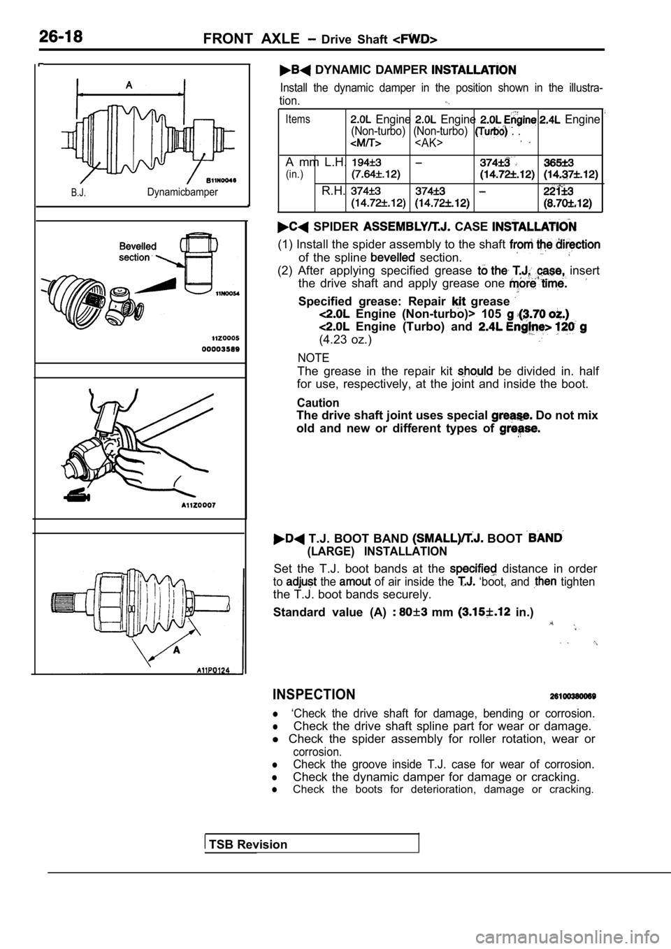
B.J.Dynamicbamper
DYNAMIC DAMPER
Install the dynamic damper in the position shown in the illustra-
tion.
Items Engine Engine Engine
(Non-turbo) (Non-turbo) . .
A mm L.H.
(in.)
R.H.
SPIDER CASE
(1) Install the spider assembly to the shaft
of the spline section.
(2) After applying specified grease insert
the drive shaft and apply grease one
Specified grease: Repair grease
Engine (Non-turbo)> 105
Engine (Turbo) and
(4.23 oz.)
NOTE
The grease in the repair kit be divided in. half
for use, respectively, at the joint and inside the boot.
Caution
The drive shaft joint uses special Do not mix
old and new or different types of
T.J. BOOT BAND BOOT
(LARGE) INSTALLATION
Set the T.J. boot bands at the distance in order
to the of air inside the ‘boot, and tighten
the T.J. boot bands securely.
Standard value (A)
mm in.)
INSPECTION
l‘Check the drive shaft for damage, bending or corro sion.
lCheck the drive shaft spline part for wear or damage.
l Check the spider assembly for roller rotation, wear or
corrosion.
lCheck the groove inside T.J. case for wear of corro sion.
lCheck the dynamic damper for damage or cracking.
lCheck the boots for deterioration, damage or cracking.
TSB Revision
Page 1533 of 2103

FRONT AXLE Drive Shaft
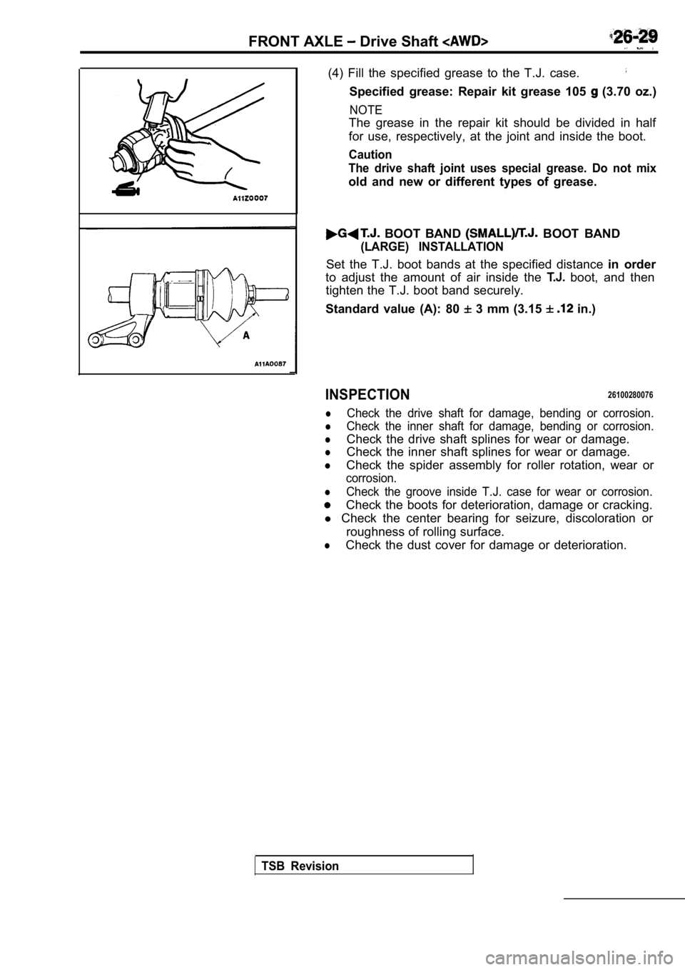
(4) Fill the specified grease to the T.J. case.
Specified grease: Repair kit grease 105 (3.70 oz.)
NOTE
The grease in the repair kit should be divided in half
for use, respectively, at the joint and inside the boot.
Caution
The drive shaft joint uses special grease. Do not m ix
old and new or different types of grease.
BOOT BAND BOOT BAND
(LARGE) INSTALLATION
Set the T.J. boot bands at the specified distance in order
to adjust the amount of air inside the
boot, and then
tighten the T.J. boot band securely.
Standard value (A): 80
3 mm (3.15 in.)
INSPECTION26100280076
lCheck the drive shaft for damage, bending or corros ion.
lCheck the inner shaft for damage, bending or corros ion.
lCheck the drive shaft splines for wear or damage.
lCheck the inner shaft splines for wear or damage.
lCheck the spider assembly for roller rotation, wear or
corrosion.
lCheck the groove inside T.J. case for wear or corro sion.
Check the boots for deterioration, damage or cracking.
l Check the center bearing for seizure, discoloration or
roughness of rolling surface.
lCheck the dust cover for damage or deterioration.
TSB Revision
Page 1560 of 2103

R E A R A X L E
(2) Remove the snap ring with ring
remove the spider assembly.
Caution
Do not disassemble the spider assembly.
(3) In case foreign objects such as water or dust i s mixed
in the grease, be sure to wash the spider assembly.
Caution
In case of having washed the spider assembly, when
assembling it, make sure to push enough grease be-
tween the spider axle and the roller so that grease may not run out.
T.J. BOOT REMOVAL
(1) Wipe the grease off of the spline portion.
(2) Remove the
boot and
N O T E
If the boots are reused, around the
drive shaft spline so that the boots
when they are removed. __
REASSEMBLY SERVICE
B.J. BOOTINSTALLATION
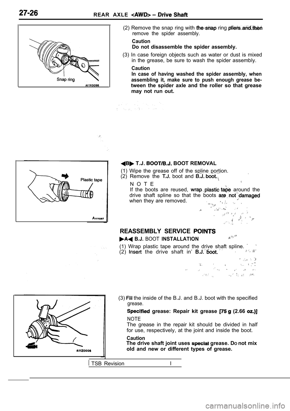
(1) Wrap plastic tape around the drive shaft spline .
(2) the drive shaft in’
. . .,
(3) the inside of the B.J. and B.J. boot with the specified
grease.
grease: Repair kit grease (2.66
NOTE
The grease in the repair kit should be divided in h alf
for use, respectively, at the joint and inside the boot.
Caution
The drive shaft joint uses grease. DOnot mix
old and new or different types of grease.
TSB Revision I
Page 1561 of 2103
REAR AXLE Drive Shaft
Lever section.
BOOT BAND BOOT
(LARGE) INSTALLATION
Be careful that the drive shaft should be. straight when
tightening the B.J. boot bands.
Caution
Always check the identification numbers
boot band levers. Never the ‘bands;
section
I
T.J. BOOT/SPIDER CASE
I N S T A L L A T I O N
the drive shaft in T.J. boot.
(2) Install the spider assembly to the shaft from t he direction
, of the section.
(3) After applying specified grease to the T.J. cas e, insert
the drive shaft and apply grease one more time.
Specified grease:
Repair kit grease
95
(3.35
105 (3.70 oz.)
NOTE
The grease in the repair kit should be divided in h alf
for use, respectively, at the joint and inside the boot.
Caution
The drive shaft joint use special grease. Do not
old and new or different types of grease.
TSB Revision
Page 1578 of 2103
REAR AXLE Differential
2 0.05 mm in.) Thickness of the spacer on
one side
(2) Push the differential case to ‘one and measure the
clearance between the gear carrier and the bearing.
(3) Measure the thickness the side bearing on
one side, select two pairs of spacers which corresp ond
to that thickness plus one half of the clearance pl us 0.05
mm, and then install one pair each to the drive pin ion
side and the drive gear side.
(4) Install side bearing spacers and differential case as-
sembly, as shown in the illustration;’
the
, .
,.
(5) Tap the side bearing spacers with a brass bar t o fit them
to the side bearing outer race.
(6)Align the mating marks on the gear carrier and the bearing’:
cap, and then tighten the bearing cap.
TSB Revision
Page 1610 of 2103
FRONT SUSPENSION Shock Absorber
Damper foinstallation
of the body
REASSEMBLY. SERVICE
COIL SPRING INSTALLATION
(1) Use the special tools to
the coil spring and
install it to the shock absorber.
Caution
Do not use an impact wrench to tighten the bolt of
the special tool.
(2) Align the edge of the coil spring to the steppe d part of
the shock
spring seat.
UPPER BRACKET ASSEMBLY
so that the position as’
in the illustration with respect the fork installation
bolt.
. SELF-LOCKING NUT . .
( 1 )
(2). the special tools and
tighten the
to- the ,
Caution
Do not use an impact wrench.
TSB Revision
Page 1623 of 2103

REAR SUSPENSION Rear Suspension
REAR SUSPENSION ASSEMBLY
REMOVAL AND INSTALLATION
Operation
(1)
(2) Lug agecompartment side trim SP (Refer to GROUP Trims)(3) Rear Crossmember Under Cover Panel Removal (Refer to GROUP 42 Under Cover.) Exhaust Pipe Removal(Refer to GROUP 15 Exhaust Pipe.)
3410033004
Post-installation Operation Center Exhaust Pipe Installation (Refer to GROUP 15Exhaust Pipe and Main Muffler,)(2) Line Bleeding drum (Referto GROUP On-vehicle (3) Luggage trim (Refer to GROUP Trims.
(4) Service Lid Installation (Refer to
(5) Brake Lever Stroke (Refer GROUP Service.)
(6) Check and Adjustment .
6
,
137-15799-114
.
l. .
3
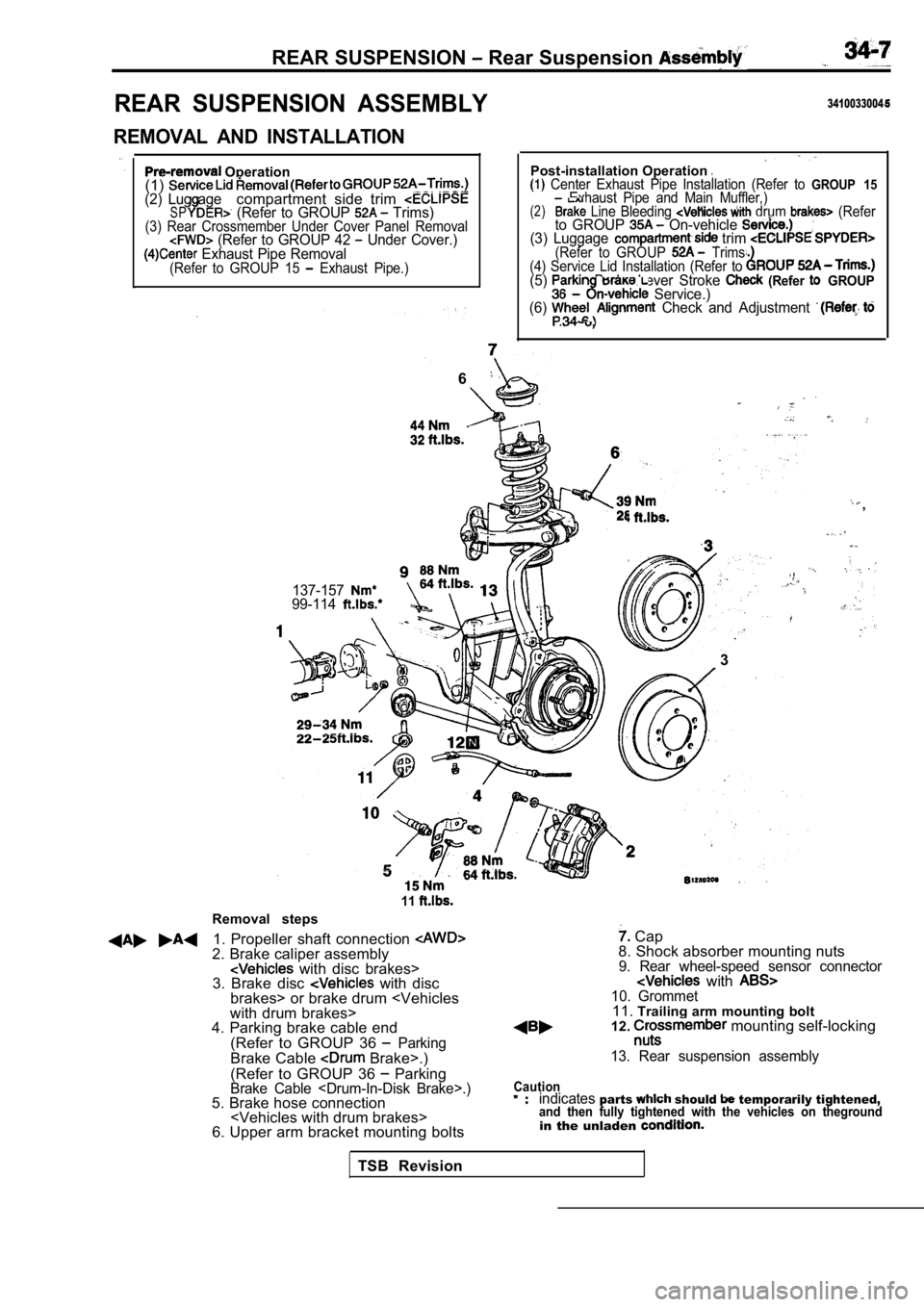
Removal steps
11
1. Propeller shaft connection 2. Brake caliper assembly with disc brakes>
3. Brake disc with disc
brakes> or brake drum
with drum brakes>
4. Parking brake cable end
(Refer to GROUP 36
ParkingBrake Cable Brake>.)
(Refer to GROUP 36
ParkingBrake Cable .)5. Brake hose connection
6. Upper arm bracket mounting bolts
Cap
8. Shock absorber mounting nuts
9. Rear wheel-speed sensor connector with 10. Grommet11. Trailing arm mounting bolt
12. mounting self-locking
13. Rear suspension assembly
Cautionindicatesparts should temporarily tightened,and then fully tightened with the vehicles on thegr oundin the unladen
TSB Revision
Page 1624 of 2103
REAR SUSPENSION Rear Suspension Assembly .
REMOVAL SERVICE POINTS
S H A F T
(1) Make mating marks on the differential-
and flange yoke, and then separate the differential carrier
assembly and the propeller shaft.
(2) Suspend the propeller shaft from the body, wire, etc,
so that there are no sharp bends..,
Caution
Be careful that there are no sharp bends in the pro pel-
ler shaft, as they may damage the joint.
CROSSMEMBER MOUNTING SELF-LOCKING
NUTS REMOVAL
After supporting the crossmember in FWD vehicles or the
differential case in AWD vehicles with a garage jack or trans-
mission jack respectively, remove the crossmember m ounting
nuts.
INSTALLATION SERVICE POINT
PROPELLER SHAFT INSTALLATION
Install with the mating marks of the differential carrier and
propeller aligned.
Caution
Tighten installation bolts and nuts after removing oil and
grease from threads to prevent them from loosening.
INSPECTION
lCheck crossmember for cracks or damage.
,
TSB Revision