1990 MITSUBISHI SPYDER ESP
[x] Cancel search: ESPPage 554 of 2103
![MITSUBISHI SPYDER 1990 Service Repair Manual E N G I N E ( T U R B O ) .
AND ENGINE> ,
Code No. Random Misfire Detected
[Comment]l Ignition system related part(s) BackgroundlIf a misfiring occurs while the engine is runni MITSUBISHI SPYDER 1990 Service Repair Manual E N G I N E ( T U R B O ) .
AND ENGINE> ,
Code No. Random Misfire Detected
[Comment]l Ignition system related part(s) BackgroundlIf a misfiring occurs while the engine is runni](/manual-img/19/57345/w960_57345-553.png)
E N G I N E ( T U R B O ) .
AND ENGINE> ,
Code No. Random Misfire Detected
[Comment]l Ignition system related part(s) BackgroundlIf a misfiring occurs while the engine is running, the engine speed suddenly changes.l
Poor crankshaft sensor l Incorrect air/fuel ratiol The engine control module checks for changes in the engine speed.
l Low compression
Check ArealEngine coolant sensor: l 5 or more have passed after the engine was started. l
liming belt broken
l Engine speed is at between 500 and 6000 l Injector failedl Engine coolant temperature is or higher, l
EGR valve failed
l Intake air temperature is or higherlEngine control l Barometric pressure is 76 (11 psi.) or higher.l Running free from sudden accelerations/deceleration s such as shift change.
Judgement Criteria. .
(change in the angular acceleration of the crankshaft is used for misfire detection.)lMisfire has occurred more frequently than allowed during the last 200 revolutions [when
the catalyst temperature is higher than
orlMisfire has occurred in 20 or more of the last 1000 revolutions (corresponding to 1.5
times the limit of emission standard.) I,
SCAN TOOL Data list
22 Crankshaft position sensor (Refer to
l Crankshaft position sensor wave form check
l Engine speed: stable
OK: Constant pulse range
OK
position sensor and
Check the injector (Refer toNG Replace
Check the fuel trim malfunction (bank 1) (Refer to IN-SPECTION PROCEDURE FOR DIAGNOSTIC TROUBLE
OK
SCAN TOOL list
21 Engine coolant temperature sensor (Refer to
OK
Check the engine coolant temperature circuit malfu nction (Refer
to INSPECTION PROCEDURE FOR DIAGNOSTICTROUBLE CODE 5.)
Check the following items.
l Check the ignition coil, spark plugs, spark plug ca bles.
l Check the compression pressure.
l Check for broken timing belt teeth.
l Check the EGR system and the EGR valve.
TSB Revision
Page 555 of 2103
![MITSUBISHI SPYDER 1990 Service Repair Manual ENGINE (TURBO)
ENGINE>
Code No. Misfire Detected (Cylin-
der-l,
[Comment]Background
lif a misfiring occurs while the engine is running, the engine speed suddenly changes.
l Th MITSUBISHI SPYDER 1990 Service Repair Manual ENGINE (TURBO)
ENGINE>
Code No. Misfire Detected (Cylin-
der-l,
[Comment]Background
lif a misfiring occurs while the engine is running, the engine speed suddenly changes.
l Th](/manual-img/19/57345/w960_57345-554.png)
ENGINE (TURBO)
ENGINE>
Code No. Misfire Detected (Cylin-
der-l,
[Comment]Background
lif a misfiring occurs while the engine is running, the engine speed suddenly changes.
l The engine control module checks for changes in the engine speed.
Check Areal 5 or more have passed after the engine was started.l Engine speed is at between 500 and 6000 l Engine coolant temperature is or higher.
l Intake air temperature is or higher
l Barometric pressure is 76 (11 psi.) or higher.
l Running free from sudden accelerations/deceleration s such as shift change.
Judgement Criteria(change in the angular acceleration of the crankshaft is used for misfire detection.)lMisfire has occurred more frequently than allowed during the last 200 revolutions [when
the catalyst temperature is higher than
or l Misfire has occurred in 20 or more of the last 1000 revolutions (corresponding to 1.5
times the limit of emission standard.)
l l Low compression l Injector failed
l Engine
Check the injector (Refer
OK
Replace
Check the following connectors: __ Repair,OK
[Check the harness wire between the ECM and the inj ectorNG ,
connector
Check the following items.
l Check the spark plugs, spark plug cables.
l Check the compression pressure
Code No. Knock Sensor 1 Circuit Malfunction
Engine (Turbo)>
l sensor failed BackgroundlThe knock sensor converts the vibration of the cyli nder block into a voltage and outputs
it. If there is a malfunction of the knock sensor, the voltage output will not change.
l The engine control module checks whether the voltag e output changes.
Check Areal Ignition switch: ONl60 or more have passed after the ignition switch was turned on or the starting sequencewasl Engine speed is higher than 2000
Judgement CriterialKnock sensor output voltage (knock sensor peak volt age in each deg period of the
crankshaft) has not changed more than 0.06 in the last consecutive 200 periods.
lOpen or shorted knock sensor circuit, or connector
l Engine control module failed
Revision
Page 574 of 2103
![MITSUBISHI SPYDER 1990 Service Repair Manual E N G I N E
A N D ,
Code No. Differential
Malfunction
[Comment]BackgroundManifold differential se.
l pressure in the intake manifold. o r l o o s e Engine control. lThe engine co MITSUBISHI SPYDER 1990 Service Repair Manual E N G I N E
A N D ,
Code No. Differential
Malfunction
[Comment]BackgroundManifold differential se.
l pressure in the intake manifold. o r l o o s e Engine control. lThe engine co](/manual-img/19/57345/w960_57345-573.png)
E N G I N E
A N D ,
Code No. Differential
Malfunction
[Comment]BackgroundManifold differential se.
l pressure in the intake manifold. o r l o o s e Engine control. lThe engine control module checks whether the voltage output by manifold differential sure sensor is within a specified range.
Check Area, Judgement Criteria.
1. Check Areal min or more have passed after the engine was start ed.[However, this is only when the engine coolant temperature is or lower
when the engine is started.]
Engine coolant temperature is not lower than Intake air temperature is not lower than Barometric pressure is 76 (11 psi.) or higher. Volumetric efficiency is 30% 55%.
Judgement Criteria . ,
Sensor output voltage has continued to be not lowe
r than [corresponding toan absolute pressure of 118 (17 psi) or higher] for 4 sec.orSensoroutput voltage has continued to be not higher than 0.1 [corresponding to ---
an absolute pressure of 2.4 (0.3 psi) or lower] for 4 sec.
2. Check Area
8 min or more have passed engine Started.
[However, this is only when the engine coolant or lower when the engine is Engine coolant temperature is not lower than Intake air temperature is not lower than Barometric pressure is 76 (11 psi.) or higher. Volumetric efficiency is 30% or lower.
Judgement Criteria ,
l Sensor output voltage is 4.2 or higher for 4 seconds [absolute pressure is 108 (16 psi.) or more]
Check Area 8 min or more have passed after the engine was sta rted.
,
.
. , ,
[However, this is only when the engine coolant temperature is or lowerwhen engine is started.]
l Engine coolant temperature is not lower than .l Intake air temperature is not lower than l Barometric pressure is 76 (11 psi.) or higher. Volumetric efficiency is 70% or higher.
Judgement Criterial Sensor output voltage is or lower for 4 seconds [absolute pressure is 46 (6.7 psi.) or less]I
TSB Revision.
Page 580 of 2103
ENGINE (TURBO)
AND Troubleshooting
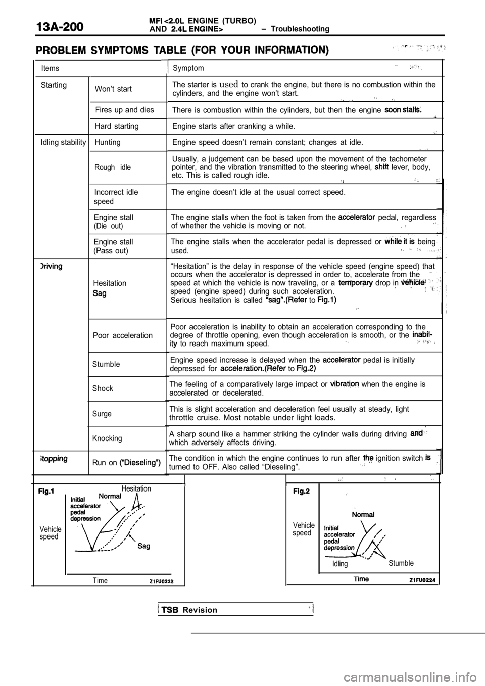
Items
Starting
Idling stabilityWon’t start Fires up and dies
Hard starting
Hunting
Rough idle
Incorrect idle
speed
Engine stall
(Die out)
Engine stall
(Pass out)
Hesitation
Poor acceleration
Stumble
Shock
Surge
Knocking
Run on
Symptom
The starter is usedto crank the engine, but there is no combustion wit hin the
cylinders, and the engine won’t start.
There is combustion within the cylinders, but then the engine
Engine starts after cranking a while.
Engine speed doesn’t remain constant; changes at id le.
Usually, a judgement can be based upon the movement of the tachometer
pointer, and the vibration transmitted to the steer ing wheel,
lever, body,
etc. This is called rough idle.
The engine doesn’t idle at the usual correct speed.
The engine stalls when the foot is taken from the
pedal, regardless
of whether the vehicle is moving or not.
The engine stalls when the accelerator pedal is dep ressed or being
used.
“Hesitation” is the delay in response of the vehicle speed (engine speed) that
occurs when the accelerator is depressed in order t o, accelerate from the
speed at which the vehicle is now traveling, or a drop in
speed (engine speed) during such acceleration.
Serious hesitation is called to
Poor acceleration is inability to obtain an acceleration corresponding to the
degree of throttle opening, even though acceleratio n is smooth, or the
to reach maximum speed.
Engine speed increase is delayed when the pedal is initially
depressed for
to
The feeling of a comparatively large impact or when the engine is
accelerated or decelerated.
This is slight acceleration and deceleration feel u sually at steady, light
throttle cruise. Most notable under light loads.
A sharp sound like a hammer striking the cylinder w alls during driving
which adversely affects driving.
The condition in which the engine continues to run after
ignition switch
turned to OFF. Also called “Dieseling”.
Vehicle
speedHesitation
Hesitation
Time
Vehicle
speed
Idling Stumble
Revision
Page 625 of 2103
ENGINE (TURBO)
AND Troubleshooting ,
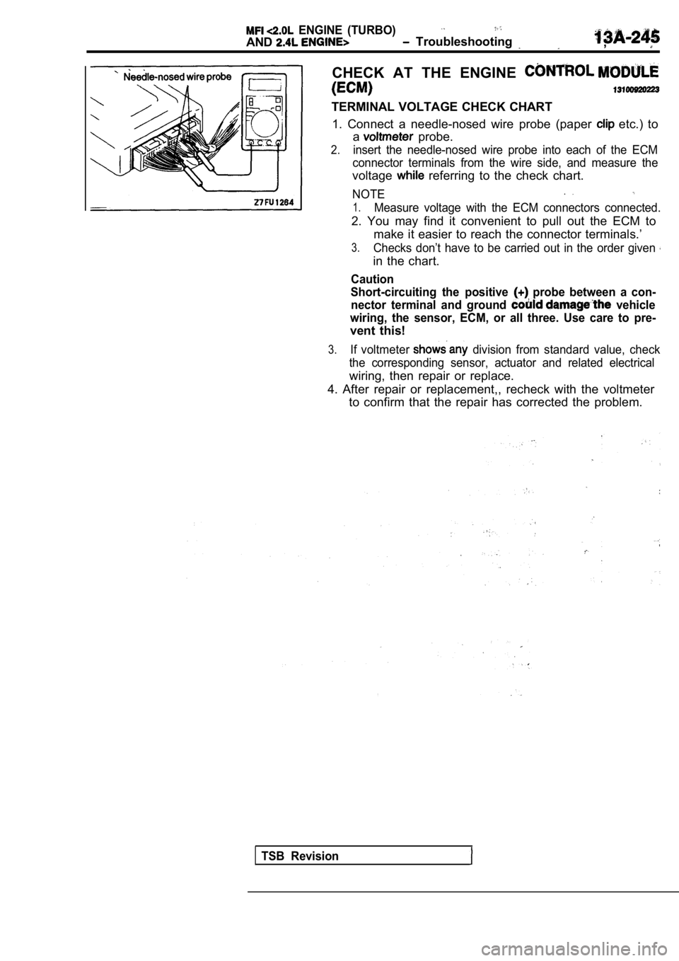
CHECK AT THE ENGINE
TERMINAL VOLTAGE CHECK CHART1. Connect a needle-nosed wire probe (paper
etc.) to
a
probe.
2.insert the needle-nosed wire probe into each of the ECM
connector terminals from the wire side, and measure the
voltage referring to the check chart.
NOTE
1.Measure voltage with the ECM connectors connected.
2. You may find it convenient to pull out the ECM to
make it easier to reach the connector terminals.’
3.Checks don’t have to be carried out in the order gi ven
in the chart.
Caution
Short-circuiting the positive
probe between a con-
nector terminal and ground
vehicle
wiring, the sensor, ECM, or all three. Use care to pre-
vent this!
3.If voltmeter division from standard value, check
the corresponding sensor, actuator and related elec trical
wiring, then repair or replace.
4. After repair or replacement,, recheck with the v oltmeter
to confirm that the repair has corrected the proble m.
TSB Revision
Page 631 of 2103
ENGINE (TURBO)
AND ENGINE>
TERMINAL RESISTANCE
1. Turn the ignition switch off.
2. Disconnect the ECM connector.
3.Measure the resistance and check for continuity bet ween
the terminals of theECM
referring to the check
NOTE
1.When measuring resistance and checking continuity’
a harness for checking contact pin pressure should’
be used instead of inserting a test probe.
2.Checks do not have to be carried in the
given in this chart.,
Caution
If resistance or continuity performed on
the wrong terminals, damage to the vehicle wiring,
sensors,
and/or ohmmeter may occur.
Use care to prevent this!
4. If the ohmmeter shows
from the normal
condition, check the corresponding sensor, actuator and
related electrical wiring, and then repair or replace.
5. After repair or replacement, recheck with the oh mmeter
to confirm that the repair or replacement
corrected
the problem.
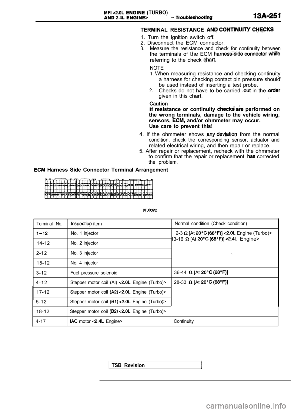
Harness Side Connector Terminal Arrangement
Terminal No. item Normal condition (Check condition)
No. 1 injector2-3 [At Engine (Turbo)>
No. 2 injector13-16 [At Engine>
14-12
2 - 1 2
No. 3 injector
15-12No. 4 injector
3 - 1 2Fuel pressure solenoid36-44 [At
4 - 1 2Stepper motor coil (Al) Engine (Turbo)>28-33 [At
17-12Stepper motor coil Engine (Turbo)>
5 - 1 2Stepper motor coil Engine (Turbo)>
18-12Stepper motor coil Engine (Turbo)>
4-17 motor Engine> Continuity
TSB Revision
Page 636 of 2103
ENGINE (TURBO)
AND
ENGINE> Troubleshooting
Analyzer
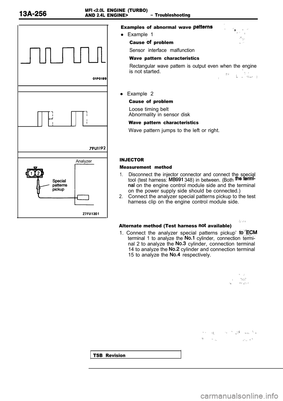
Examples of abnormal wave ,
l Example 1
Cause problem
Sensor interface malfunction
Wave pattern characteristics
Rectangular wave pattern is output even when the en gine
is not started.
l Example 2
Cause of problem
Loose timing belt
Abnormality in sensor disk
Wave pattern characteristics
Wave pattern jumps to the left or right.
INJECTOR
Measurement method
1.Disconnect the injector connector and connect the s pecial
tool (test harness:
348) in between. (Both
on the engine control module side and the terminal
on the power supply side should be connected.)
2.Connect the analyzer special patterns pickup to the test
harness clip on the engine control module side.
Alternate method (Test harness available)
1. Connect the analyzer special patterns pickup’
terminal 1 to analyze the cylinder, connection termi-
nal 2 to analyze the cylinder, connection terminal
14 to analyze the
cylinder and connection terminal
15 to analyze the
respectively.
TSB Revision
Page 638 of 2103
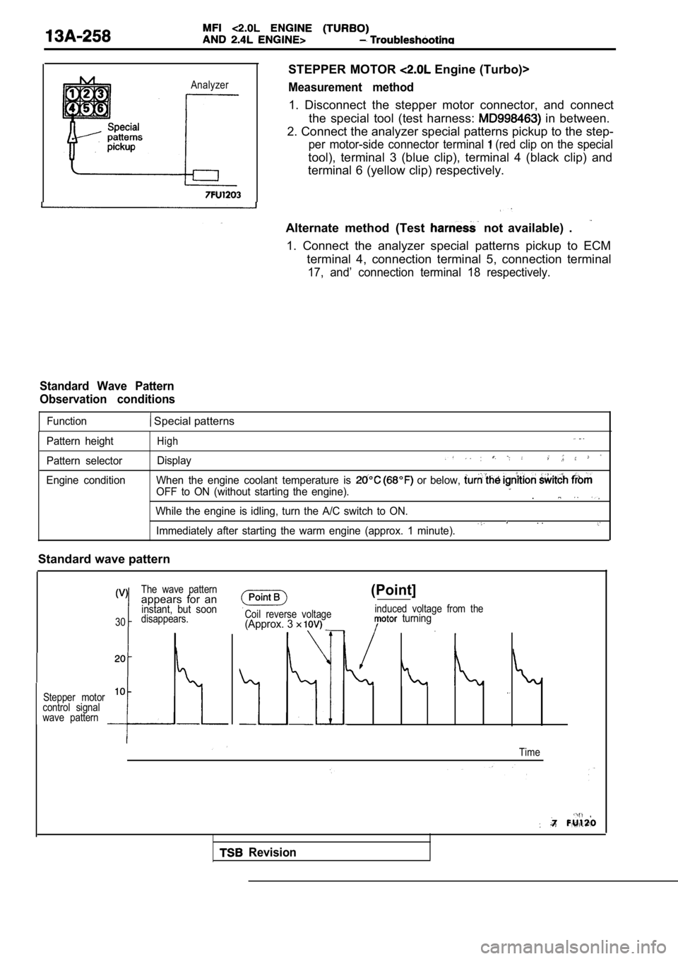
Analyzer
STEPPER MOTOR Engine (Turbo)>
Measurement method
1. Disconnect the stepper motor connector, and connect
the special tool (test harness:
in between.
2. Connect the analyzer special patterns pickup to the step-
per motor-side connector terminal (red clip on the special
tool), terminal 3 (blue clip), terminal 4 (black clip) and
terminal 6 (yellow clip) respectively.
Alternate method (Test
not available) .
1. Connect the analyzer special patterns pickup to ECM
terminal 4, connection terminal 5, connection termi nal
17, and’ connection terminal 18 respectively.
Standard Wave Pattern
Observation conditions
Function Special patterns
Pattern height
Pattern selector
Engine conditionHigh
Display
When the engine coolant temperature is or below,
OFF to ON (without starting the engine)..
While the engine is idling, turn the A/C switch to ON.. .Immediately after starting the warm engine (approx. 1 minute).
Standard wave pattern
The wave patternappears for aninstant, but soon
30disappears.
Stepper motor
10
control signal
wave pattern
Coil reverse voltage(Approx. 3
(Point]
induced voltage from the turning
Time
Revision