1990 MITSUBISHI SPYDER ESP
[x] Cancel search: ESPPage 396 of 2103
ENGINE (NON-TURBO)> Troubleshooting
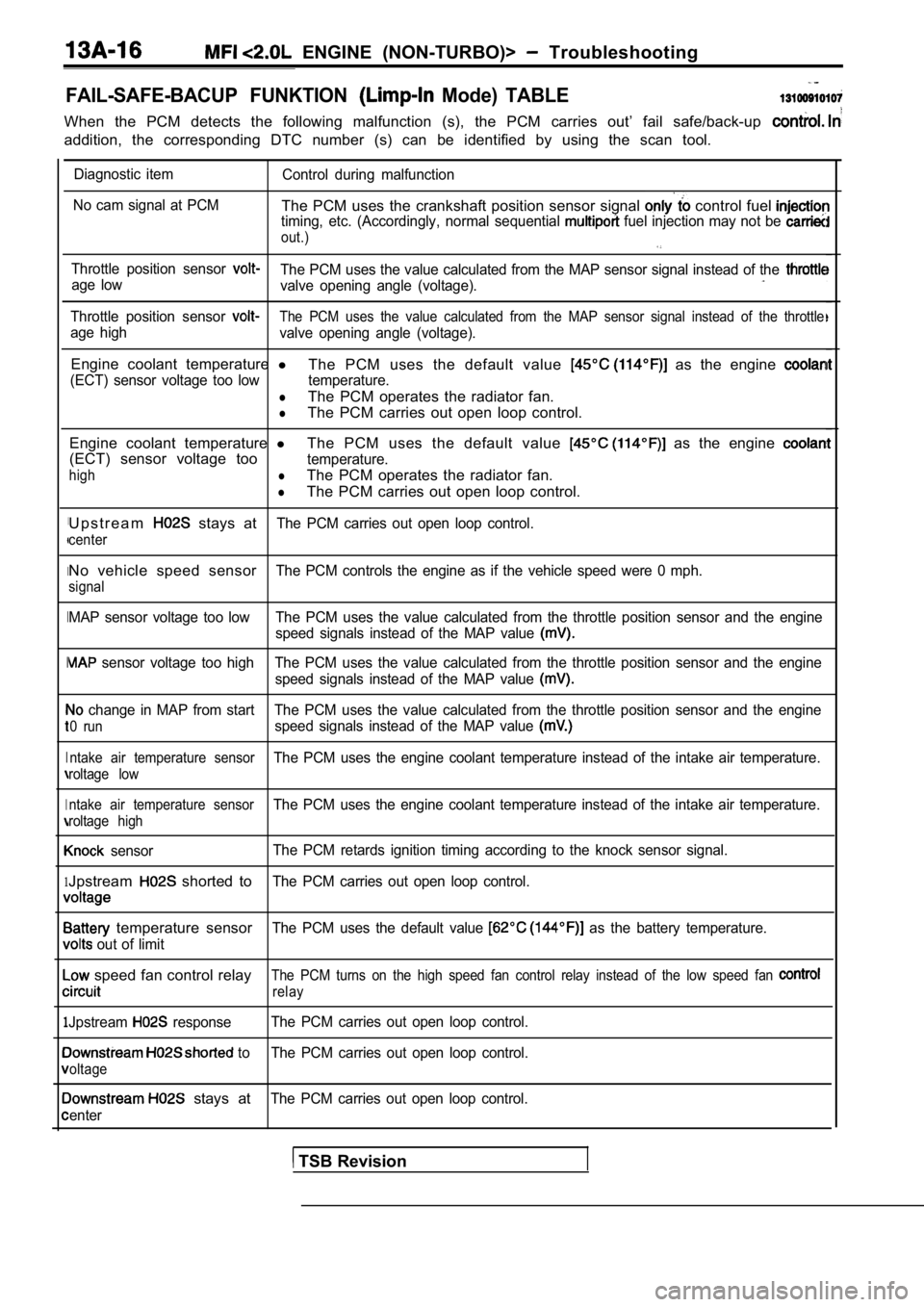
FAIL-SAFE-BACUP FUNKTION Mode) TABLE
When the PCM detects the following malfunction (s), the PCM carries out’ fail safe/back-up
addition, the corresponding DTC number (s) can be i dentified by using the scan tool.
I
I
I
I
I
1
1
Diagnostic item
Control during malfunction
No cam signal at PCM
The PCM uses the crankshaft position sensor signal control fuel timing, etc. (Accordingly, normal sequential fuel injection may not be
out.)
Throttle position sensor The PCM uses the value calculated from the MAP sens or signal instead of the age low
valve opening angle (voltage).
Throttle position sensor The PCM uses the value calculated from the MAP sens or signal instead of the throttle
age high
valve opening angle (voltage).
Engine coolant temperature l
The PCM uses the default value as the engine
(ECT) sensor voltage too low temperature.
lThe PCM operates the radiator fan.
lThe PCM carries out open loop control.
Engine coolant temperature lThe PCM uses the default value
as the engine
(ECT) sensor voltage tootemperature.
highlThe PCM operates the radiator fan.
lThe PCM carries out open loop control.
U p s t r e a m
stays atThe PCM carries out open loop control.
center
No vehicle speed sensorThe PCM controls the engine as if the vehicle speed were 0 mph.
signal
MAP sensor voltage too low The PCM uses the value ca lculated from the throttle position sensor and the engine
speed signals instead of the MAP value
sensor voltage too high The PCM uses the value calc ulated from the throttle position sensor and the engine
speed signals instead of the MAP value
change in MAP from start The PCM uses the value cal culated from the throttle position sensor and the engine
0 runspeed signals instead of the MAP value
ntake air temperature sensorThe PCM uses the engine coolant temperature instead of the intake air temperature.
roltage low
ntake air temperature sensor
The PCM uses the engine coolant temperature instead of the intake air temperature.
roltage high
sensorThe PCM retards ignition timing according to the kn
ock sensor signal.
Jpstream shorted toThe PCM carries out open loop control.
temperature sensorThe PCM uses the default value as the battery temperature.
out of limit
speed fan control relayThe PCM turns on the high speed fan control relay i nstead of the low speed fan
relay
Jpstream responseThe PCM carries out open loop control.
to The PCM carries out open loop control.
oltage
stays atThe PCM carries out open loop control.
enter
TSB Revision
Page 400 of 2103
E N G I N E ( N O N - T U R B O ) >
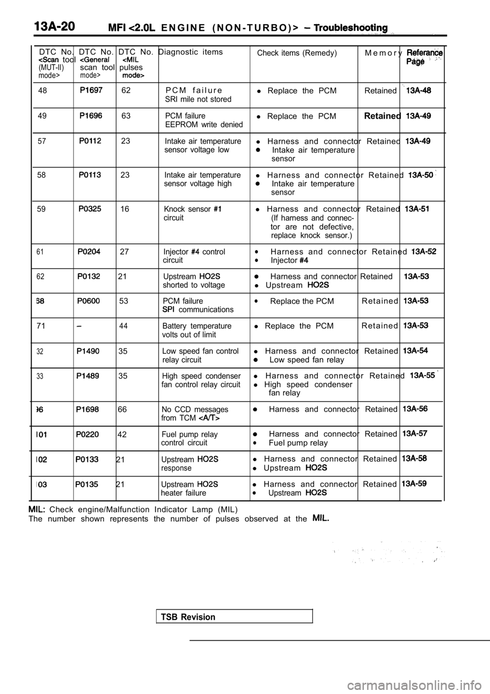
DTC No. DTC No. DTC No. Diagnostic items tool (MUT-II)scan tool pulsesmode>mode>
48 62 P C M f a i l u r e
SRI mile not storedCheck items (Remedy)
l
Replace the PCM M e m o r yRetained
49 63PCM failurel
Replace the PCM Retained
EEPROM write denied
57 23Intake air temperaturel Harness and connector Retained
sensor voltage lowIntake air temperature
sensor
58
23Intake air temperaturel H a r n e s s a n d c o n n e c t o r R e t a i n e d
sensor voltage highIntake air temperature
sensor
59
16Knock sensor
circuit
l Harness and connector Retained
(If harness and connec-
tor are not defective,
replace knock sensor.)
61 27
62 21
53
Injector control
circuit
Upstream
shorted to voltage
PCM failure
communications
lH a r n e s s a n d c o n n e c t o r R e t a i n e d lInjector
Harness and connector Retained
l Upstream
lReplace the PCM R e t a i n e d
7144Battery temperature
volts out of limitl Replace the PCM R e t a i n e d
32 35
33 35
Low speed fan controll
Harness and connector Retained
relay circuitLow speed fan relay
High speed condenserl H a r n e s s a n d c o n n e c t o r R e t a i n e d
fan control relay circuitl High speed condenser
fan relay
66No CCD messages
from TCM Harness and connector Retained
42
21
21
Fuel pump relay
control circuit
Upstream
response
Upstream
heater failure
Harness and connector Retained
lFuel pump relay
l Harness and connector Retained
l Upstream
l Harness and connector Retained lUpstream
Check engine/Malfunction Indicator Lamp (MIL)
The number shown represents the number of pulses ob served at the
TSB Revision
Page 438 of 2103
![MITSUBISHI SPYDER 1990 Service Repair Manual ENGINE (NON-TURBO)>
Scan tool 102
Code General scan tool
No. Response
21
[Comment]
Backgroundl Heated oxygen sensor failed
l Exhaust system failed
During closed-loop operation the PC MITSUBISHI SPYDER 1990 Service Repair Manual ENGINE (NON-TURBO)>
Scan tool 102
Code General scan tool
No. Response
21
[Comment]
Backgroundl Heated oxygen sensor failed
l Exhaust system failed
During closed-loop operation the PC](/manual-img/19/57345/w960_57345-437.png)
ENGINE (NON-TURBO)>
Scan tool 102
Code General scan tool
No. Response
21
[Comment]
Backgroundl Heated oxygen sensor failed
l Exhaust system failed
During closed-loop operation the PCM monitors the h eated oxygen sensor response ratefor proper operation.-Pipes
lResponse rate is the time required for the heated o xygen sensor to switch from - s e a l sonce the sensor is exposed to a richer than the ide al air fuel mixture.
If the response rate is below the acceptable limit, the PCM stores a diagnostic troublel harness and connectors l
l PCM failed .code.Range of Checkl Engine coolant temperature greater than l Approximately three minutes elapsed time after star t-up.
lVehicle has operated at more than for 75 seconds with engine coolant temperatureat.
l Power steering pressure switch is offl Vehicle is at idle with engine speed between 512 an d 864 lThis test may be inhibited if the A/C is cycling to o rapidly. (Testing with the off issuggested)Set Condition.Heated oxygen sensor does not produce 0.67 volt out put and/or does not perform enoughswitches within the test threshold time of 6 seconds.
NGCheck the exhaust l Check for cracks or exhaust leaks. Repair
OK
Check the following connectors: N G Repair
OK
Check trouble symptom.
NG
NG
Check the harness wire between Repair
sensor (front).
OK
[Replace the heated oxygen sensor (front).
Revision
Page 464 of 2103
I E N G I N E
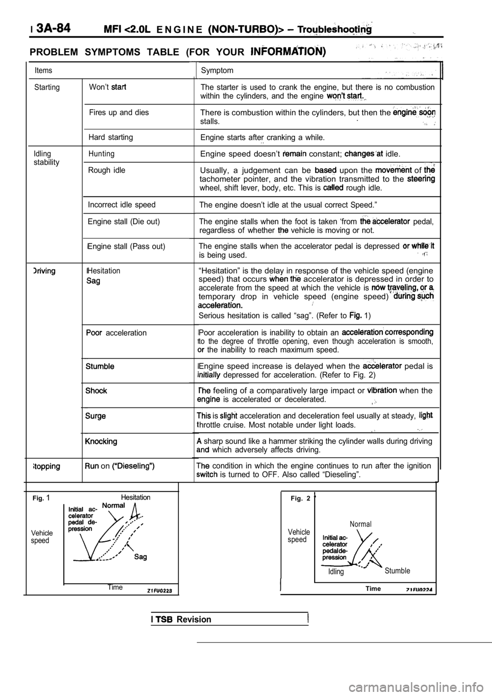
PROBLEM SYMPTOMS TABLE (FOR YOUR
ItemsSymptom
StartingWon’tThe starter is used to crank the engine, but there is no combustion
within the cylinders, and the engine
Fires up and diesThere is combustion within the cylinders, but then the
stalls..
Engine starts after cranking a while.Hard starting
Idling
stability
HuntingEngine speed doesn’t constant; idle.
Usually, a judgement can be
upon the of
tachometer pointer, and the vibration transmitted to the
wheel, shift lever, body, etc. This is rough idle.
Rough idle
The engine doesn’t idle at the usual correct Speed. ”
The engine stalls when the foot is taken ‘from
pedal,
regardless of whether
vehicle is moving or not.
Incorrect idle speed
Engine stall (Die out)
The engine stalls when the accelerator pedal is dep ressed
is being used.
Engine stall (Pass out)
Hesitation“Hesitation” is the delay in response of the vehicle speed (engine
speed) that occurs
accelerator is depressed in order to
accelerate from the speed at which the vehicle is
temporary drop in vehicle speed (engine speed)
Serious hesitation is called “sag”. (Refer to 1)
Poor acceleration is inability to obtain an
to the degree of throttle opening, even though acce leration is smooth,
the inability to reach maximum speed.
acceleration
Engine speed increase is delayed when the pedal is
depressed for acceleration. (Refer to Fig. 2)
feeling of a comparatively large impact or when the
is accelerated or decelerated.,
is acceleration and deceleration feel usually at steady,
hrottle cruise. Most notable under light loads.
sharp sound like a hammer striking the cylinder wa lls during driving
which adversely affects driving.
condition in which the engine continues to run after the ignition
is turned to OFF. Also called “Dieseling”.
on
Fig.1Hesitation
Hesitation
Vehicle
speed
Fig. 2
Vehicle
speedNormal
Idling Stumble
ITimeTime
I Revision
Page 518 of 2103
ENGINE
AND ENGINE> G e n e r a l
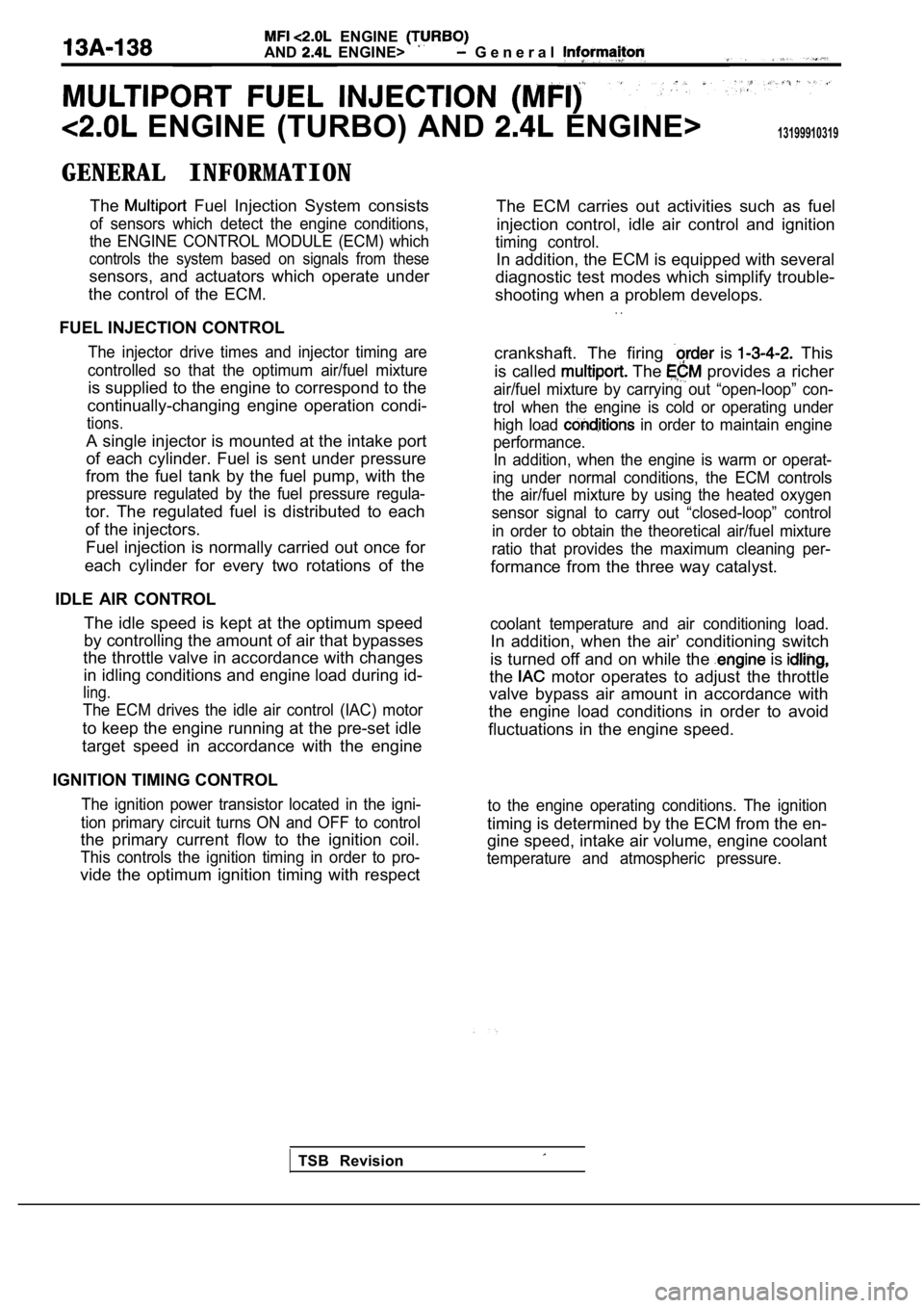
ENGINE (TURBO) AND ENGINE>13199910319
GENERAL INFORMATIONThe
Fuel Injection System consists
of sensors which detect the engine conditions,
the ENGINE CONTROL MODULE (ECM) which
controls the system based on signals from these
sensors, and actuators which operate under
the control of the ECM.
FUEL INJECTION CONTROL
The injector drive times and injector timing are
controlled so that the optimum air/fuel mixture
is supplied to the engine to correspond to the
continually-changing engine operation condi-
tions.
A single injector is mounted at the intake port
of each cylinder. Fuel is sent under pressure
from the fuel tank by the fuel pump, with the
pressure regulated by the fuel pressure regula-
tor. The regulated fuel is distributed to each
of the injectors.
Fuel injection is normally carried out once for
each cylinder for every two rotations of the
IDLE AIR CONTROL The idle speed is kept at the optimum speed
by controlling the amount of air that bypasses
the throttle valve in accordance with changes
in idling conditions and engine load during id-
ling.
The ECM drives the idle air control (IAC) motor
to keep the engine running at the pre-set idle
target speed in accordance with the engine
IGNITION TIMING CONTROL
The ignition power transistor located in the igni-
tion primary circuit turns ON and OFF to control
the primary current flow to the ignition coil.
This controls the ignition timing in order to pro-
vide the optimum ignition timing with respect The ECM carries out activities such as fuel
injection control, idle air control and ignition
timing control.
In addition, the ECM is equipped with several
diagnostic test modes which simplify trouble-
shooting when a problem develops.
. .
crankshaft. The firing is This
is called
The provides a richer
air/fuel mixture by carrying out “open-loop” con-
trol when the engine is cold or operating under high load
in order to maintain engine
performance. In addition, when the engine is warm or operat-
ing under normal conditions, the ECM controls
the air/fuel mixture by using the heated oxygen
sensor signal to carry out “closed-loop” control
in order to obtain the theoretical air/fuel mixture
ratio that provides the maximum cleaning per-
formance from the three way catalyst.
coolant temperature and air conditioning load.
In addition, when the air’ conditioning switch
is turned off and on while the
is
the motor operates to adjust the throttle
valve bypass air amount in accordance with
the engine load conditions in order to avoid
fluctuations in the engine speed.
to the engine operating conditions. The ignition
timing is determined by the ECM from the en-
gine speed, intake air volume, engine coolant
temperature and atmospheric pressure.
TSB Revision
Page 519 of 2103
ENGINE (TURBO)
ENGINE>
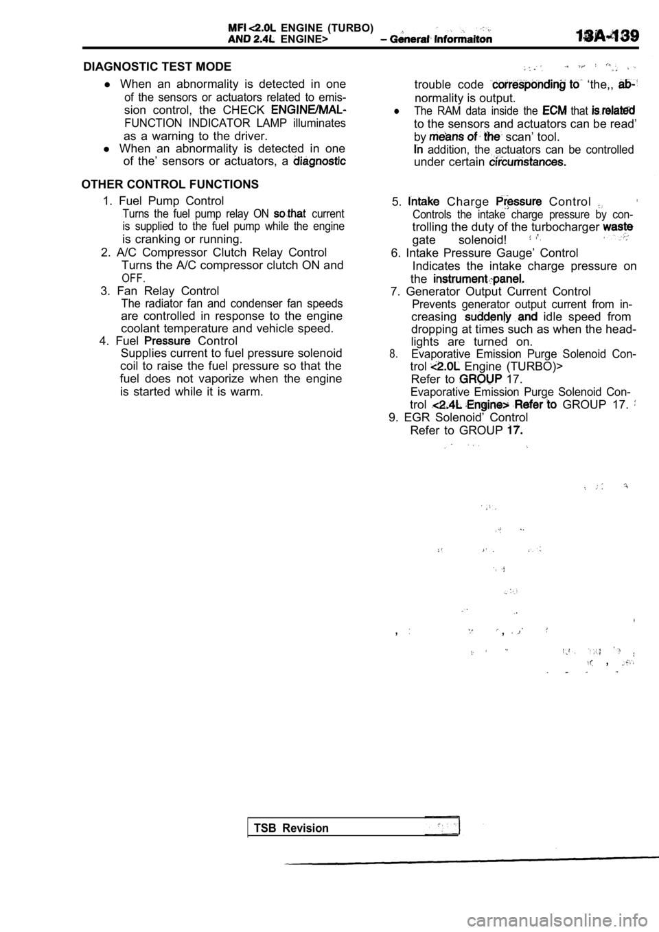
DIAGNOSTIC TEST MODEl When an abnormality is detected in one
of the sensors or actuators related to emis-
sion control, the CHECK
FUNCTION INDICATOR LAMP illuminates
as a warning to the driver.
l When an abnormality is detected in one
of the’ sensors or actuators, a
OTHER CONTROL FUNCTIONS
1. Fuel Pump Control
Turns the fuel pump relay ON current
is supplied to the fuel pump while the engine
is cranking or running.
2. A/C Compressor Clutch Relay Control Turns the A/C compressor clutch ON and
OFF.
3. Fan Relay Control
The radiator fan and condenser fan speeds
are controlled in response to the engine
coolant temperature and vehicle speed.
4. Fuel
Control
Supplies current to fuel pressure solenoid
coil to raise the fuel pressure so that the
fuel does not vaporize when the engine
is started while it is warm.
trouble code ‘the,,
normality is output.
lThe RAM data inside the that
to the sensors and actuators can be read’
by
scan’ tool.
addition, the actuators can be controlled
under certain
5. Charge Control
Controls the intake charge pressure by con-
trolling the duty of the turbocharger
gate solenoid!
6. Intake Pressure Gauge’ Control Indicates the intake charge pressure on
the
7. Generator Output Current Control
Prevents generator output current from in-
creasing idle speed from
dropping at times such as when the head-
lights are turned on.
8.Evaporative Emission Purge Solenoid Con-
trol Engine (TURBO)>
Refer to
17.
Evaporative Emission Purge Solenoid Con-
trol GROUP 17.
9. EGR Solenoid’ Control
Refer to GROUP
,,
,
TSB Revision
Page 531 of 2103
ENGINE (TURBO)
AND
ENGINE>
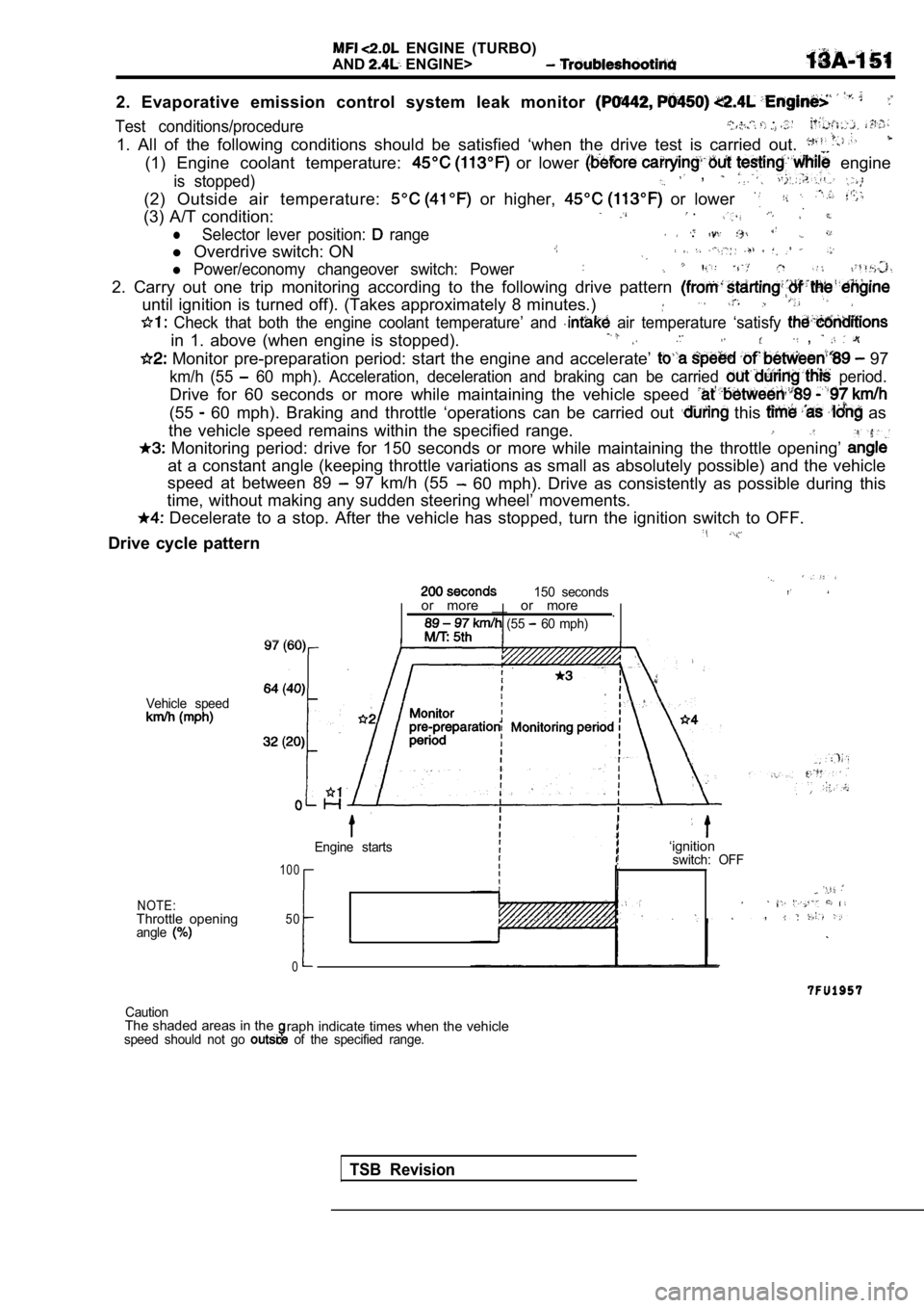
2. Evaporative emission control system leak monitor
Test conditions/procedure , . .
1. All of the following conditions should be satisfied ‘when the drive test is carried out.
(1) Engine coolant temperature: or lower engine
is stopped) ,
(2) Outside air temperature: or higher, or lower
(3) A/T condition: .
lSelector lever position: range .
l Overdrive switch: ON
l Power/economy changeover switch: Power
2. Carry out one trip monitoring according to the f ollowing drive pattern
until ignition is turned off). (Takes approximately 8 minutes.)
Check that both the engine coolant temperature’ an d air temperature ‘satisfy
in 1. above (when engine is stopped). ,
Monitor pre-preparation period: start the engine and accelerate’ 97
km/h (55 60 mph). Acceleration, deceleration and braking ca n be carried period.
Drive for 60 seconds or more while maintaining the vehicle speed
(55 60 mph). Braking and throttle ‘operations can be carried out this as
the vehicle speed remains within the specified rang e.
Monitoring period: drive for 150 seconds or more w hile maintaining the throttle opening’
at a constant angle (keeping throttle variations as small as absolutely possible) and the vehicle
speed at between 89
97 km/h (55 60 mph). Drive as consistently as possible during this
time, without making any sudden steering wheel’ mov ements.
Decelerate to a stop. After the vehicle has stopped, turn the ignition switch to OFF.
Drive cycle pattern
150 seconds
Vehicle speed
NOTE:Throttle openingangle
or more __ or more
.
(55 60 mph)
Engine starts
1 0 0
50
0
I
‘ignitionswitch: OFF
,
CautionThe shaded areas in theraph indicate times when the vehiclespeed should not go of the specified range.
TSB Revision
Page 534 of 2103
ENGINE (TURBO)
AND
ENGINE> Troubleshooting
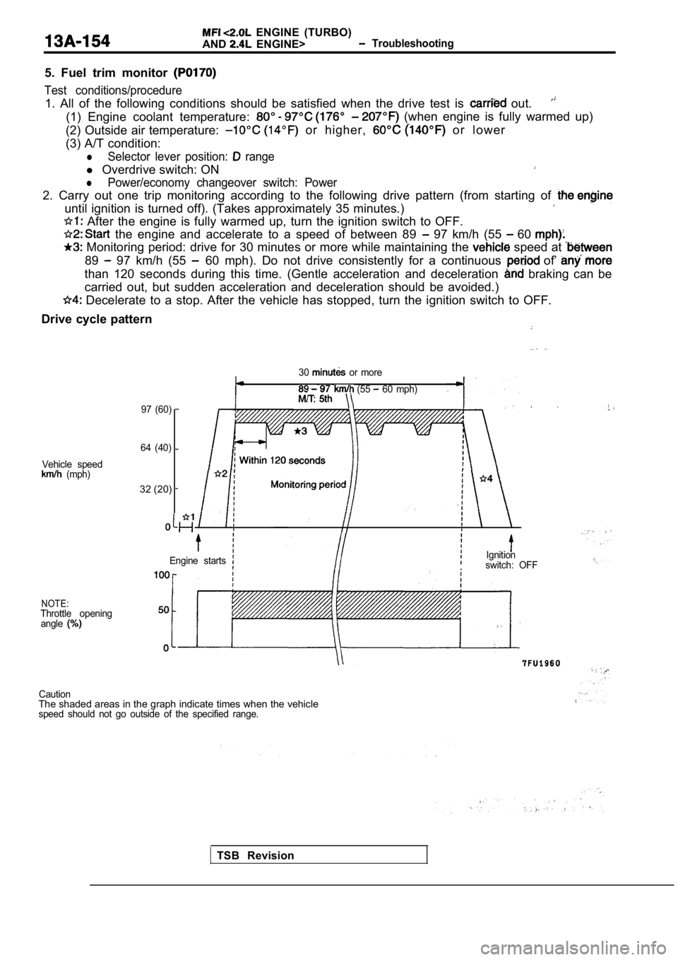
5. Fuel trim monitor
Test conditions/procedure
1. All of the following conditions should be satisf ied when the drive test is out.
(1) Engine coolant temperature: (when engine is fully warmed up)
(2) Outside air temperature:
or higher, o r l o w e r
(3) A/T condition:
lSelector lever position: range
l Overdrive switch: ON
lPower/economy changeover switch: Power
2. Carry out one trip monitoring according to the f ollowing drive pattern (from starting of
until ignition is turned off). (Takes approximately 35 minutes.)
After the engine is fully warmed up, turn the igni tion switch to OFF.
the engine and accelerate to a speed of between 89 97 km/h (55 60
Monitoring period: drive for 30 minutes or more while maintaining the speed at
89 97 km/h (55 60 mph). Do not drive consistently for a continuous of’
than 120 seconds during this time. (Gentle acceleration and deceleration braking can be
carried out, but sudden acceleration and decelerati on should be avoided.)
Decelerate to a stop. After the vehicle has stopped, turn the ignition switch to OFF.
Drive cycle pattern
30 or more
(55 60 mph)
Vehicle speed
(mph)
NOTE:Throttle opening angle
97 (60)
64 (40)
32 (20)
Engine startsIgnitionswitch: OFF
CautionThe shaded areas in the graph indicate times when t he vehiclespeed should not go outside of the specified range.
TSB Revision