1990 MITSUBISHI SPYDER ESP
[x] Cancel search: ESPPage 1771 of 2103
PARKING BRAKES, parking Brake Brake>
Shoe
Paint
Shoe-to-anchor spring (rear)
Forward
R E M O V A L
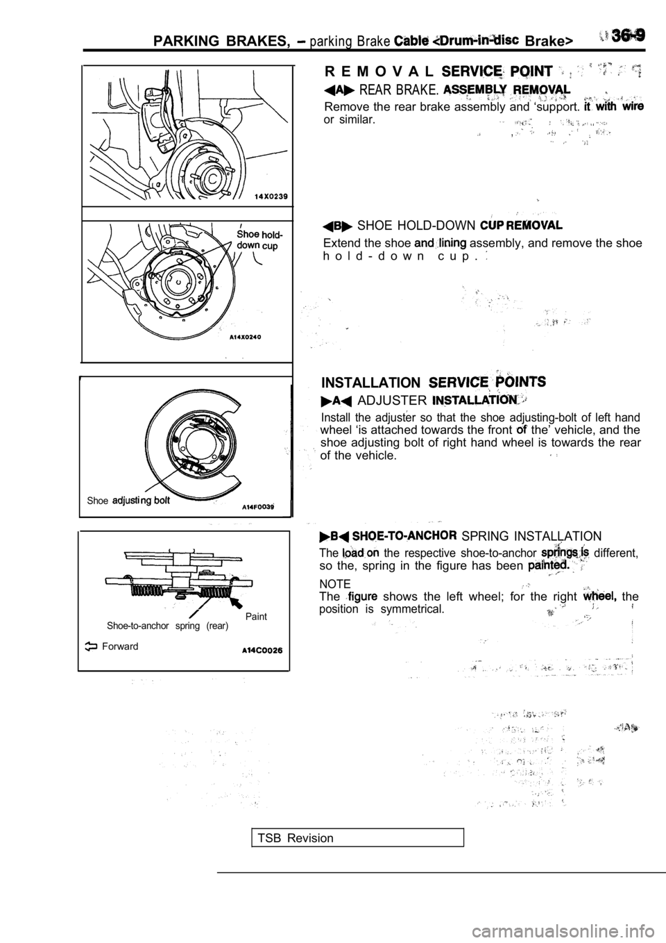
REAR BRAKE.
Remove the rear brake assembly and ‘support.
or similar.
,
SHOE HOLD-DOWN
Extend the shoe assembly, and remove the shoe
h o l d - d o w n c u p .
INSTALLATION
ADJUSTER
Install the adjuster so that the shoe adjusting-bol t of left hand
wheel ‘is attached towards the front the’ vehicle, and the
shoe adjusting bolt of right hand wheel is towards the rear
of the vehicle.
SPRING INSTALLATION
The the respective shoe-to-anchor different,
so the, spring in the figure has been
NOTE
The shows the left wheel; for the right the
position is symmetrical.
TSB Revision
Page 1773 of 2103
PARKING BRAKES
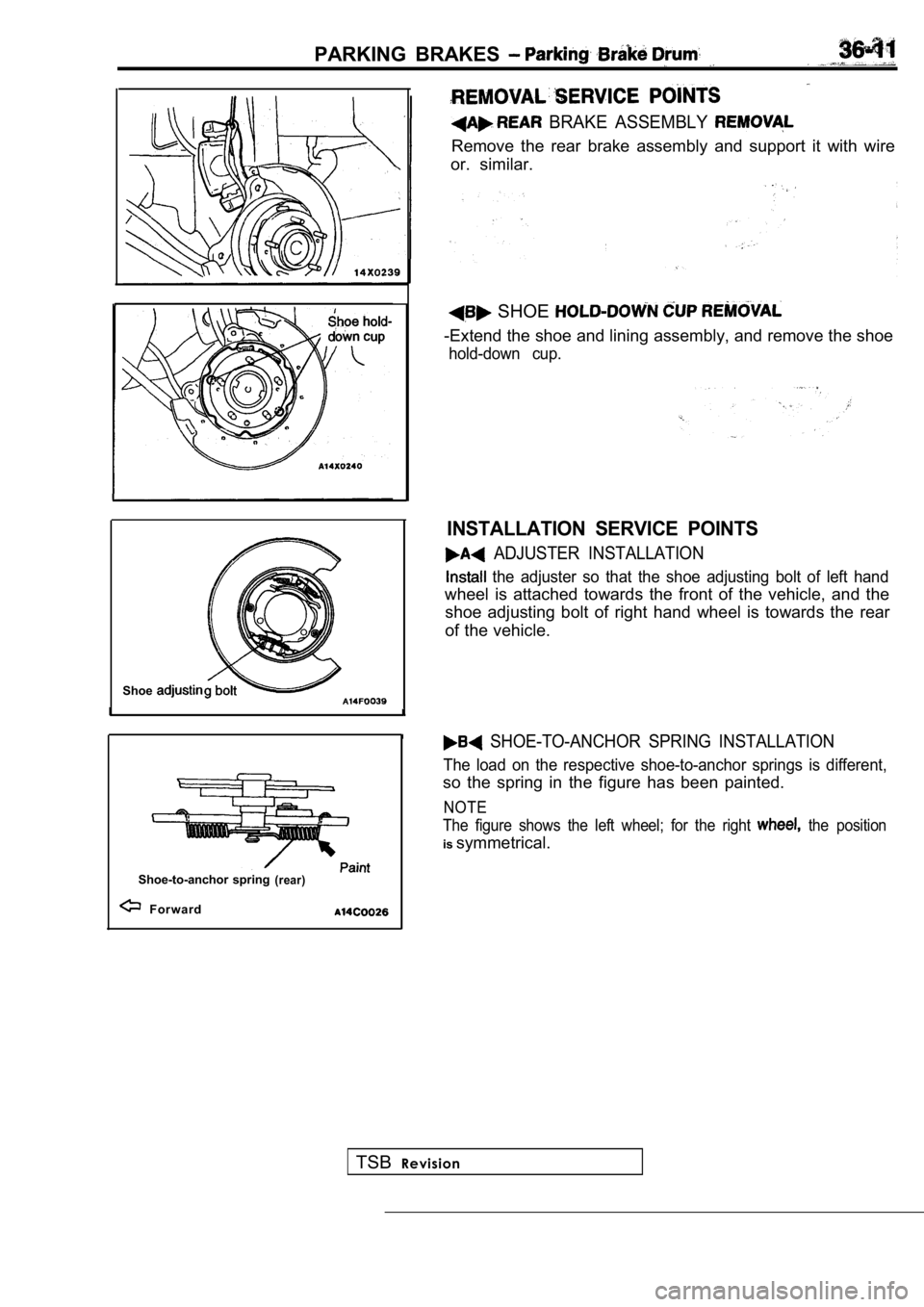
BRAKE ASSEMBLY
Remove the rear brake assembly and support it with wire
or. similar.
Shoe
Shoe-to-anchor spring(rear)
Forward
SHOE
-Extend the shoe and lining assembly, and remove th e shoe
hold-down cup.
INSTALLATION SERVICE POINTS
ADJUSTER INSTALLATION
the adjuster so that the shoe adjusting bolt of left hand
wheel is attached towards the front of the vehicle, and the
shoe adjusting bolt of right hand wheel is towards the rear
of the vehicle.
SHOE-TO-ANCHOR SPRING INSTALLATION
The load on the respective shoe-to-anchor springs i s different,
so the spring in the figure has been painted.
NOTE
The figure shows the left wheel; for the right
the position
is symmetrical.
TSB Revision
Page 1775 of 2103
CONTENTS
GENERAL INFORMATION. . . . . . . . . . . . . . . . . . 2POWER STEERING GEAR . . . . . . . . . . 18
LUBRICANTS. . . . . . . . . . . . . . . . . . . . . . . . . . . . . .
3P O W E R S T E E R I N G H O S E ’ S
Engine . . . . .
ON-VEHICLE SERVICE . . . . . . . . . . . . . . . . . . . . . 7 Engine (Turbo) and . . . 47
Bleeding. . . . . . . . . . . . . . . . . . . . . . . . . . . . . . . . . . . .9
Checking Steering Wheel Return to Center
. . . .8
Fluid Level Check. . . . . . . . . . . . . . . . . . . . . . . . . . .8
Fluid Replacement. . . . . . . . . . . . . . . . . . . . . . . . . . .9
Oil Pump Test
. . . . . . . . . . . . . . . . . . . . .
Power Steering Pressure Switch Check
. . . . . . .13
Stationary Steering Effort Check. . . . . . . . . . . . . .8
Steering Angle Check. . . . . . . . . . . . . . . . . . . . . . . .7
Steering Wheel Free Play Check. . . . . . . . . . . . . . .7
Tie Rod End Ball Joint Breakaway Torque Check
. . . . . . . . . . . . . . . . . . . . . . . . . . . . . . . . . . . . . . . . . . . . .
7
POWER STEERING OIL PUMP
Engine (Non-turbo)> . . . . . . . . . . . . . . .
Engine (Turbo) and Engine> . . . 39
SEALANTS. . . . . . . . . . . . . . . . . . . . . . . . . . . . . . . .4
SERVICE SPECIFICATIONS . . . . . . . . . . . . . . . . . 3
SPECIAL TOOLS. . . . . . . . . . . . . . . . . . . . . . . . . . .4
STEERING WHEEL AND
. . . . . . . . . . 14
WARNINGS REGARDING SERVICING OF SUPPLEMENTAL (SRS) EQUIPPED
WARNING!(1)Improper service or maintenance of any component of the SRS, or any SRS-related component, can lead
the SRS inoperative).(2) Service or maintenance of any SRS component or component must be performed MITSUBISHI dealer.(3) MITSUBISHI dealer personnel must this and especially its GROUP straint System (SRS) and GROUP 00 -Maintenance beginning any service or maintenance of any com-
ponent of the SRS or any
NOTEThe includes the following components: SRS light, air bag module, and interconnecting wiring.Other SRS-related components (that may have to be r emoved/installed in with service or maintenance) are indi-
cated in the table of contents by an asterisk
Page 1776 of 2103
STEERING General Information
G E N E R A L I N F O R M A T I O N
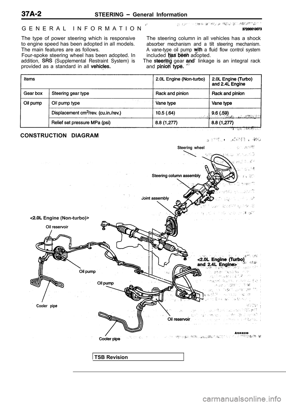
The type of power steering which is responsive
to engine speed has been adopted in all models.
The main features are as follows. The steering column in all vehicles has a shock
absorber mechanism and a tilt steering mechanism.
Four-spoke steering wheel has been adopted. In
A vane-type oil pump a fluid flow control system
addition, (Supplemental Restraint System) is
included adopted.
provided as a standard in all
The gear linkage is an integral rack
and
CONSTRUCTION DIAGRAM,
Steering wheel
Cooler pipe
Engine (Non-turbo)>
TSB Revision
Page 1840 of 2103
BODY Windshield and Window Glass
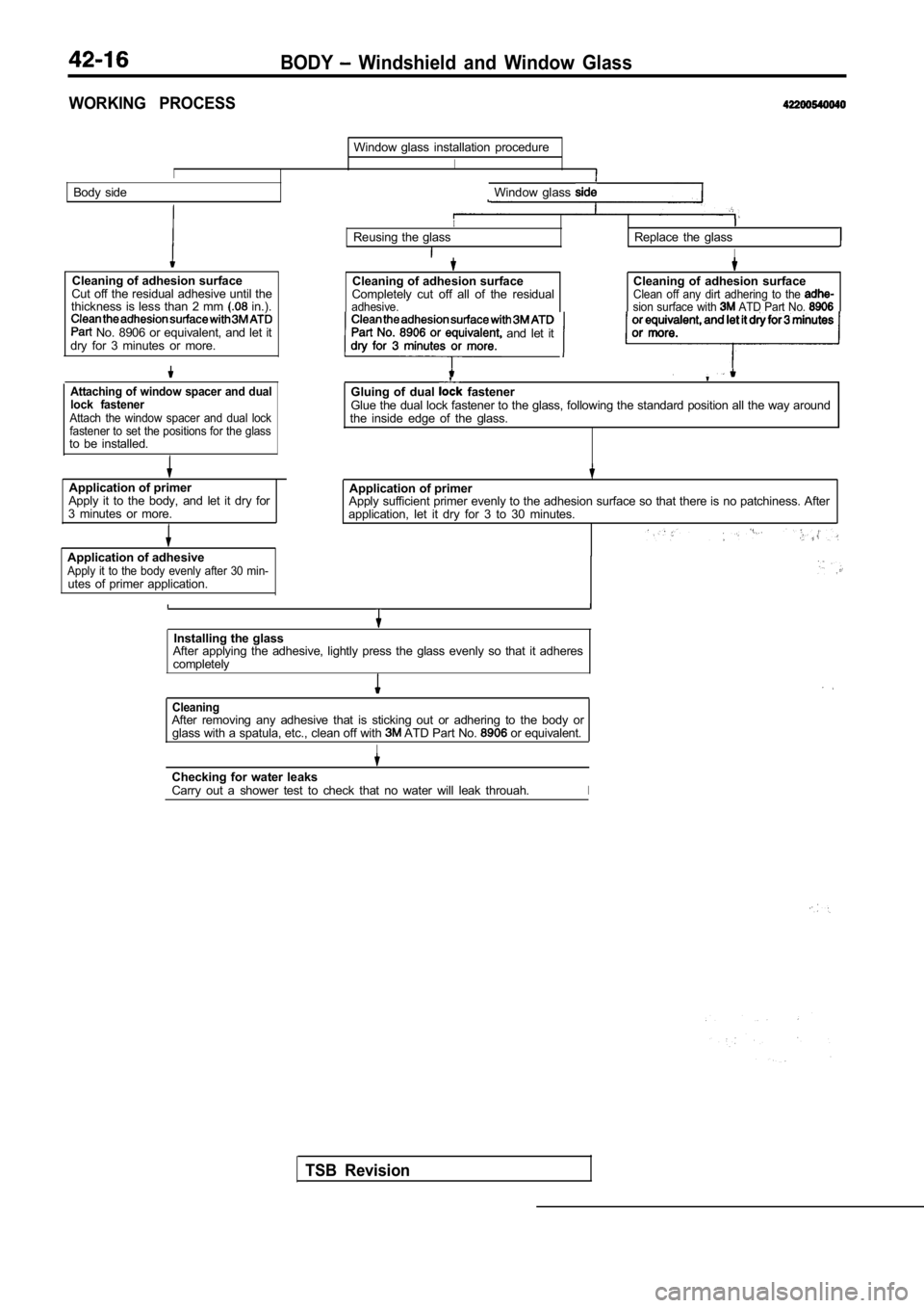
WORKING PROCESS
I
Window glass installation procedure
I
Body sideWindow glass
Cleaning of adhesion surface
Cut off the residual adhesive until the
thickness is less than 2 mm
in.).
No. 8906 or equivalent, and let it
dry for 3 minutes or more.
Attaching of window spacer and dual
lock fastener
Attach the window spacer and dual lock
fastener to set the positions for the glass
to be installed.
Application of primer Application of primer
Apply it to the body, and let it dry for
3 minutes or more. Apply sufficient primer evenly to the adhesion surf
ace so that there is no patchiness. After
application, let it dry for 3 to 30 minutes.
Application of adhesive
Apply it to the body evenly after 30 min-utes of primer application.
IReusing the glassReplace the glass
I
Cleaning of adhesion surface
Completely cut off all of the residual
adhesive.
Cleaning of adhesion surfaceClean off any dirt adhering to the sion surface with ATD Part No. or equivalent, and let it dry for 3 minutesPart No. 8906 or equivalent and let it
Gluing of dual fastenerGlue the dual lock fastener to the glass, following the standard position all the way around
the inside edge of the glass.
Installing the glass
After applying the adhesive, lightly press the glas s evenly so that it adheres
completely
TSB Revision
CleaningAfter removing any adhesive that is sticking out or adhering to the body or
glass with a spatula, etc., clean off with ATD Part No. or equivalent.
I
Checking for water leaks
Carry out a shower test to check that no water will leak throuah.I
Page 1931 of 2103
E X T E R I O R
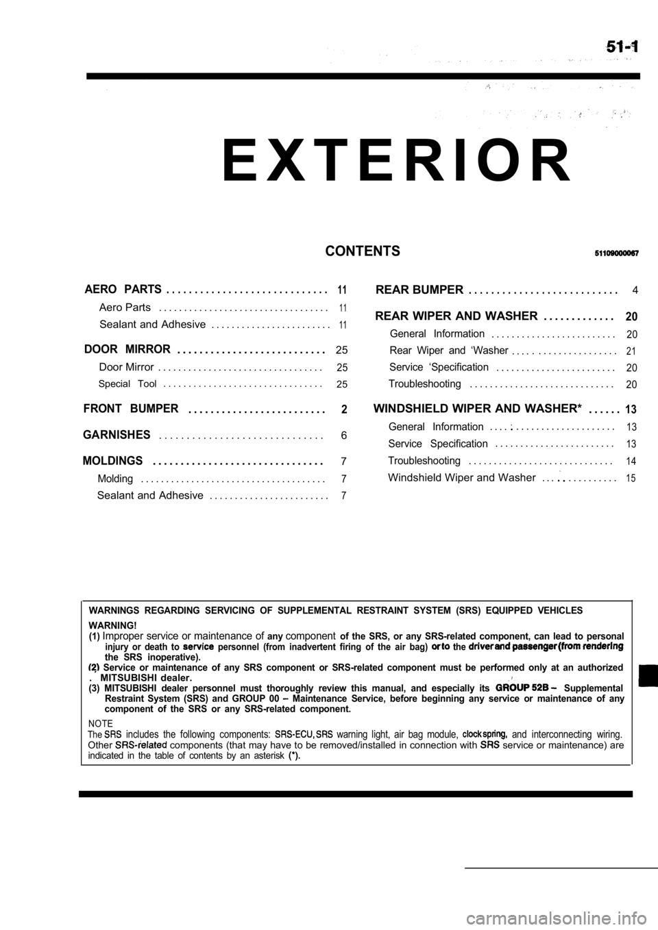
CONTENTS
AERO PARTS. . . . . . . . . . . . . . . . . . . . . . . . . . . . .11REAR BUMPER. . . . . . . . . . . . . . . . . . . . . . . . . . .4
Aero Parts . . . . . . . . . . . . . . . . . . . . . . . . . . . . . . . . . .
11REAR WIPER AND WASHER . . . . . . . . . . . . .20Sealant and Adhesive . . . . . . . . . . . . . . . . . . . . . . . .11General Information. . . . . . . . . . . . . . . . . . . . . . . . .20
DOOR MIRROR. . . . . . . . . . . . . . . . . . . . . . . . . . . 25Rear Wiper and ‘Washer. . . .. . . . . . . . . . . . . . . . .21
Door Mirror . . . . . . . . . . . . . . . . . . . . . . . . . . . . . . . . .25Service ‘Specification. . . . . . . . . . . . . . . . . . . . . . . .20
Special Tool . . . . . . . . . . . . . . . . . . . . . . . . . . . . . . . .
25Troubleshooting. . . . . . . . . . . . . . . . . . . . . . . . . . . . .20
FRONT BUMPER. . . . . . . . . . . . . . . . . . . . . . . . .2WINDSHIELD WIPER AND WASHER* . . . . . .13
6General Information. . . .. . . . . . . . . . . . . . . . . . . .13GARNISHES. . . . . . . . . . . . . . . . . . . . . . . . . . . . . .Service Specification. . . . . . . . . . . . . . . . . . . . . . . .13
MOLDINGS. . . . . . . . . . . . . . . . . . . . . . . . . . . . . . .7Troubleshooting. . . . . . . . . . . . . . . . . . . . . . . . . . . . .14
Molding. . . . . . . . . . . . . . . . . . . . . . . . . . . . . . . . . . . . .7Windshield Wiper and Washer . . .. . . . . . . . . .15
Sealant and Adhesive . . . . . . . . . . . . . . . . . . . . . . . .7
WARNINGS REGARDING SERVICING OF SUPPLEMENTAL RESTRA INT SYSTEM (SRS) EQUIPPED VEHICLES
WARNING! (1)
Improper service or maintenance of anycomponentof the SRS, or any SRS-related component, can lead to personalinjury or death to personnel (from inadvertent firing of the air bag) the the SRS inoperative). Service or maintenance of any SRS component or SRS -related component must be performed only at an authorized. MITSUBISHI dealer.(3) MITSUBISHI dealer personnel must thoroughly rev iew this manual, and especially its Supplemental
Restraint System (SRS) and GROUP 00 Maintenance Service, before beginning any service or maintenance of any
component of the SRS or any SRS-related component.
NOTE
The includes the following components: warning light, air bag module, and interconnecting wiring.Other components (that may have to be removed/installed in connection with service or maintenance) areindicated in the table of contents by an asterisk
Page 1959 of 2103
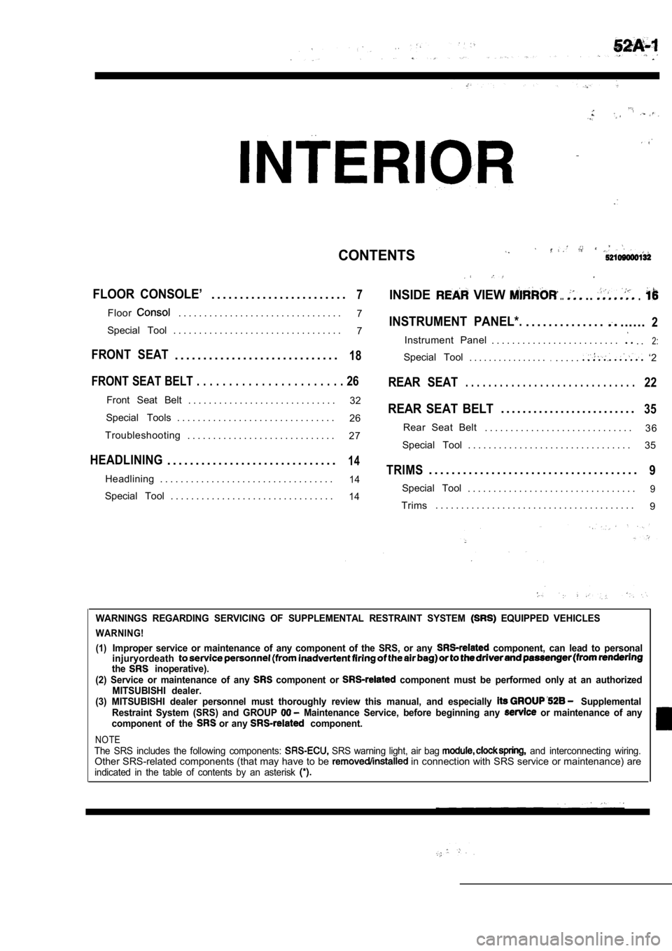
CONTENTS
FLOOR CONSOLE’. . . . . . . . . . . . . . . . . . . . . . . .7INSIDE VIEW .....
Floor. . . . . . . . . . . . . . . . . . . . . . . . . . . . . . . .7INSTRUMENT PANEL*.. . . . . . . . . . . . . .......2Special Tool . . . . . . . . . . . . . . . . . . . . . . . . . . . . . . . . . 7
Instrument Panel . . . . . . . . . . . . . . . . . . . . . . . . .. .2:
FRONT SEAT. . . . . . . . . . . . . . . . . . . . . . . . . . . . .18Special Tool. . . . . . . . . . . . . . . ... . . . .. ‘2
FRONT SEAT BELT . . . . . . . . . . . . . . . . . . . . . . . 26REAR SEAT. . . . . . . . . . . . . . . . . . . . . . . . . . . . . .22
Front Seat Belt
. . . . . . . . . . . . . . . . . . . . . . . . . . . . . 32REAR SEAT BELT. . . . . . . . . . . . . . . . . . . . . . . . .35Special Tools . . . . . . . . . . . . . . . . . . . . . . . . . . . . . . .
26
3 6
Troubleshooting Rear Seat Belt
. . . . . . . . . . . . . . . . . . . . . . . . . . . . .
. . . . . . . . . . . . . . . . . . . . . . . . . . . . . 27
Special Tool . . . . . . . . . . . . . . . . . . . . . . . . . . . . . . . . 35
HEADLINING. . . . . . . . . . . . . . . . . . . . . . . . . . . . . .14TRIMS. . . . . . . . . . . . . . . . . . . . . . . . . . . . . . . . . . . . .9Headlining . . . . . . . . . . . . . . . . . . . . . . . . . . . . . . . . . .14Special Tool. . . . . . . . . . . . . . . . . . . . . . . . . . . . . . . . .9Special Tool . . . . . . . . . . . . . . . . . . . . . . . . . . . . . . . .14Trims. . . . . . . . . . . . . . . . . . . . . . . . . . . . . . . . . . . . . . .
9
WARNINGS REGARDING SERVICING OF SUPPLEMENTAL RESTRA INT SYSTEM EQUIPPED VEHICLES
WARNING!
(1)
Improper service or maintenance of any component of the SRS, or any component, can lead to personal
injuryordeath
the inoperative).
(2) Service or maintenance of any component or component must be performed only at an authorized
MITSUBISHI dealer.
(3) MITSUBISHI dealer personnel must thoroughly rev iew this manual, and especially
Supplemental
Restraint System (SRS) and GROUP Maintenance Service, before beginning any or maintenance of any
component of the or any component.
NOTEThe SRS includes the following components: SRS warning light, air bag and interconnecting wiring.Other SRS-related components (that may have to be in connection with SRS service or maintenance) areindicated in the table of contents by an asterisk
Page 1976 of 2103
INTERIOR Front Seat
FRONT SEAT
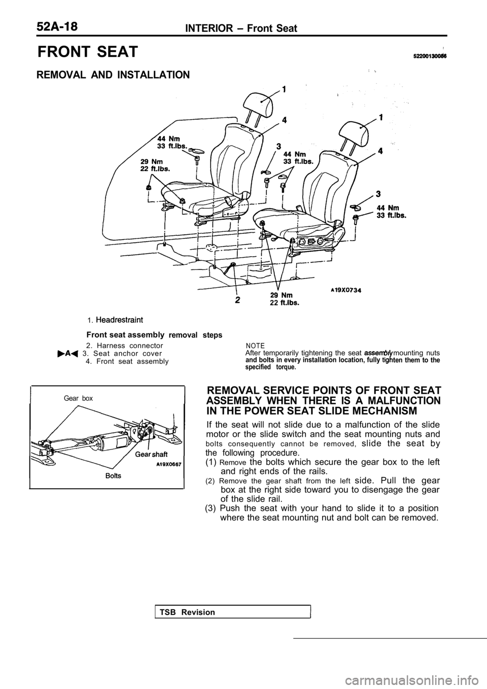
REMOVAL AND INSTALLATION
1.
Front seat assembly
2. Harness connector
3. Seat anchor cover 4. Front seat assembly
22
removal steps
Gear box
TSB Revision
N O T EAfter temporarily tightening the seat mounting nutsand bolts in every installation location, fully ten them to thespecified torque.
REMOVAL SERVICE POINTS OF FRONT SEAT
ASSEMBLY WHEN THERE IS A MALFUNCTION
IN THE POWER SEAT SLIDE MECHANISM
If the seat will not slide due to a malfunction of the slide
motor or the slide switch and the seat mounting nut s and
b o l t s c o n s e q u e n t l y c a n n o t b e r e m o v e d , slide the seat by
the following procedure.
(1)Remove the bolts which secure the gear box to the left
and right ends of the rails.
(2) Remove the gear shaft from the left side. Pull the gear
box at the right side toward you to disengage the g ear
of the slide rail.
(3) Push the seat with your hand to slide it to a p osition
where the seat mounting nut and bolt can be removed .