Page 1695 of 2103

ABS Troubleshooting
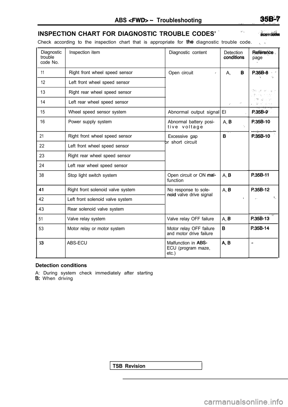
INSPECTION CHART FOR DIAGNOSTIC TROUBLE CODES’
Check according to the inspection chart that is appropriate for diagnostic trouble code.
Diagnostic
Inspection item Diagnostic contentDetection
trouble
code No.
11Right front wheel speed sensor
12Left front wheel speed sensor
13Right rear wheel speed sensor
14Left rear wheel speed sensor
15Wheel speed sensor system
16Power supply system
21Right front wheel speed sensor
22Left front wheel speed sensor
23 Right rear wheel speed sensor
24Left rear wheel speed sensor
38Stop light switch system
Right front solenoid valve system
42Left front solenoid valve system
43 Rear solenoid valve system
51Valve relay system
53Motor relay or motor system Open circuit
A,
Abnormal output signal El.
Abnormal battery posi-A,t i v e v o l t a g e
Excessive gap
or short circuit
Open circuit or ON A,
function
No response to sole-
A, valve drive signal
Valve relay OFF failureA,
Motor relay OFF failure
and motor drive failure
ABS-ECU Malfunction in
ECU (program maze,
etc.)
Detection conditions
A: During system check immediately after starting
When driving
TSB Revision
page
Page 1709 of 2103

ABS
Needle-nosed wire probe .I
I
Connector terminal. arrangement for
troubleshooting
Terminal arrangement shown on the
special tool connector
0 0 0 0 0 0 7 8
ABS-ECU CHECK
TERMINAL VOLTAGE CHECK CHART
1. Connect a needle-nosed to
a voltmeter probe. . .
2. the needle-nosed into each of the
ABS-ECU connector terminals from. the wire side, an d
measure the voltage while referring to the
NOTE
1. Measure voltage with the ABS-ECU
connected.,
2.You may find it convenient to pull out the ABS-ECU to make it easier to reach the connector terminals. :
3.Checks don’t have to be the order
in the chart.
Caution
Short-circuiting the positive probe between a
connector terminal and
could damage the
vehicle wiring, the sensor, ABS-ECU, or three.
care to prevent this!
3.If voltmeter shows any division from standard value , check
the corresponding electrical
wiring, then repair or replace.
4. After
or replacement, recheck with the voltmeter’
to confirm that the repair has corrected the proble m.
ABS-ECU Connector Terminal Arrangement
Caution
Use the special tool to the ABS-ECU
voltage and
2. The ABS-ECU connector terminal
troubleshooting is different from the terminal
arrangement shown on the special tool
So take the readings from the numbers of
the special tool when
Example
TSB Revision
Page 1711 of 2103
RESISTANCE AND CONTINUITY CHECK
1. Turn. the ignition switch to OFF.
2. Disconnect the ABS-ECU connector.
3.Measure the resistance and check for continuity bet ween
the terminals of the ABS-ECU connector
while referring to the check chart.
measuring resistance and checking continuity,
a ‘harness for checking contact pin pressure should
be used instead of inserting a test probe.
2.
Checks do not have to be carried out in the order
given
this chart.
Caution
or continuity checks are performed on
the
damage to the
and/or ohmmeter may occur.
care to prevent this!
If the ohmmeter shows any deviation from the norma l
condition, check the corresponding sensor, actuator and
related electrical wiring, and then repair or replace.
5. After repair or replacement, recheck with the oh mmeter
to confirm that the repair or replacement has corre cted
t h e p r o b l e m .
7
sensor switch: OFF
ABS-ECU groundAt all timesContinuity
TSB Revision
Page 1713 of 2103

Service
Connector terminal arrangement
Terminal arrangement shown on thespecial tool connector
0 0 0 0 0 0 7 6
L - L - -
,
I
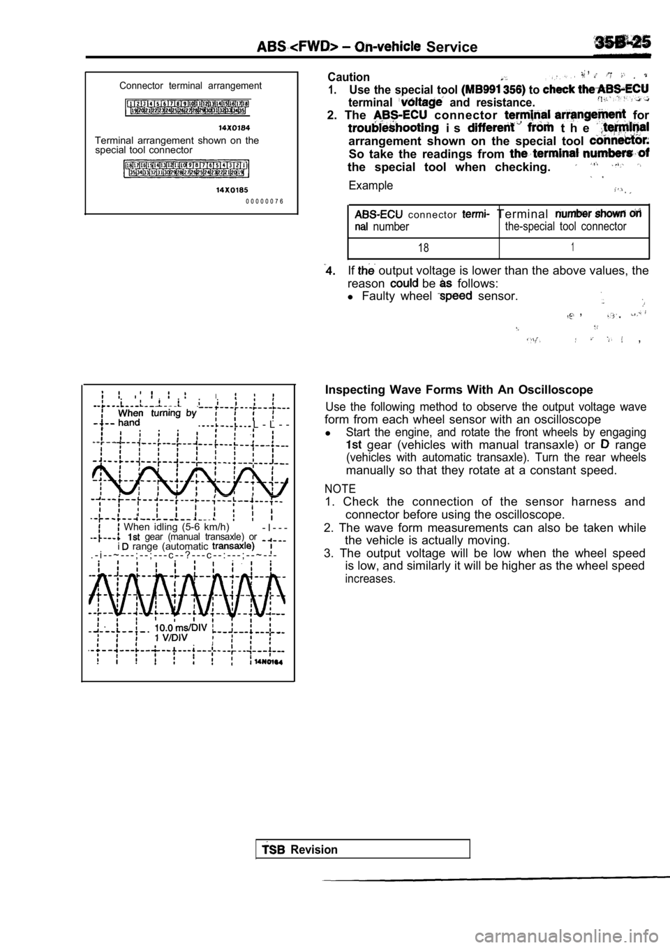
When idling (5-6 km/h) gear (manual transaxle) or- I - - -
. - i - - ~ - - - ; - - ; - - - c - - ? - - - c - - : - - - ; - - ~ - - - i range (automatic
,Caution,
1.Use the special tool to
terminal and resistance.
2. The connector for
i s t h e
arrangement shown on the special tool
So take the readings from
the special tool when checking.
Example
c o n n e c t o r Terminal
numberthe-special tool connector
181
If output voltage is lower than the above values, the
reason
be follows:
l Faulty wheel
sensor.
,
,
Inspecting Wave Forms With An Oscilloscope
Use the following method to observe the output volt age wave
form from each wheel sensor with an oscilloscope
l
Start the engine, and rotate the front wheels by en gaging
gear (vehicles with manual transaxle) or range
(vehicles with automatic transaxle). Turn the rear wheels
manually so that they rotate at a constant speed.
NOTE
1. Check the connection of the sensor harness and
connector before using the oscilloscope.
2. The wave form measurements can also be taken whi le
the vehicle is actually moving.
3. The output voltage will be low when the wheel sp eed
is low, and similarly it will be higher as the whee l speed
increases.
Revision
Page 1736 of 2103
INSPECTION CHART FOR DIAGNOSTIC TROUBLE
.. .
C h e c k a c c o r d i n g t o t h e f o r t h e d i a g n o s t i c t r o u b l e
Diagnostic Inspection item
troubleDiagnostic content. p a g e
code No. .
,
11Right front sensorOpen circuit
.,
15Wheel speed sensor system
21 s e n s o r
output signal
Broken
sensor or OFF
22
41
42
Stop light switch system Open circuit or ON malfunction
Left front solenoid valve systemNo response to
Right front solenoid valve systemdrive signal
43
51
52
Rear solenoid valve system
Valve relay system
Motor relay or motor system
The currents flowing
right and left valves different
under the same condition:,
Valve relay OFF failure
Motor relay OFF failure and
motor drive failure
55ABS-ECU ABS-ECU internal failure
(program maze, etc.)
Detection conditions
A: During system check immediately after starting B: While driving
Revision
Page 1748 of 2103
t h e . I-,..,
.. .
Short-circuiting the positive probe between a
connector terminal and ground could damage the
wiring, the sensor, ABS-ECU, or all three. Use
care to this!
3 .
If voltmeter any division from standard value, check
the
sensor, actuator and related electrical
wiring, then repair or replace.
4. , After
replacement, recheck with the voltmeter
the repair has corrected the problem.
Connector terminal arrangement for
troubleshooting
Terminal arrangement shown on the tool connector
0 0 0 0 0 0 7 6 ABS-ECU Connector Terminal Arrangement
Use the special tool to check the ABS-ECU
voltage and resistance.
2. The
connector terminal arrangement for
“troubleshooting is different from the terminal
shown on the special tool connector.
So take the readings from the terminal numbers of
the special tool when checking.
Example
ABS-ECU connector terminalTerminal number shown on
number for troubleshootingthespecial tool connector
181
TSB Revision
Page 1750 of 2103

ABS Troubleshooting
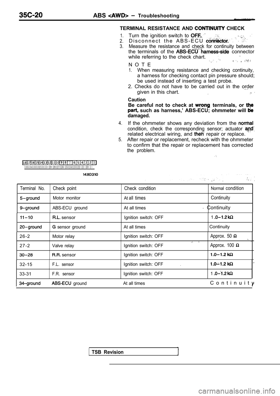
TERMINAL RESISTANCE AND
CHECK
7 13513413313213113~29~28127126~25124123122~21~20~1~
1.
2.
3.
4.
5.
Turn the ignition switch to
D i s c o n n e c t t h e A B S - E C U
Measure the resistance and check for continuity bet ween
the terminals of the connector
while referring to the check chart.
N O T E
,
1.When measuring resistance and checking continuity,
a harness for checking contact pin pressure should;
be used instead of inserting a test probe.
2. Checks do not have to be carried out in the orde r
given in this chart.
Caution
Be careful not to check at terminals, or
such as harness,’ ABS-ECU; ohmmeter will
damaged.
If the ohmmeter shows any deviation from the
condition, check the corresponding sensor; actuator
related electrical wiring, and repair or replace.
After repair or replacement, recheck with the ohmmeter
to confirm that the repair or replacement has corre cted
the problem.
Terminal No.Check point Check conditionNormalcondition
Motor monitorAtall timesContinuity
ABS-ECU ground At all times Continuity
sensor
sensor groundIgnition switch: OFF
1At all timesContinuity
2 6 - 2
Motor relay
2 7 - 2Valve relay
sensor
Ignition switch: OFF
Ignition switch: OFF
Ignition switch: OFFApprox. 50
Approx. 100
32-15F.L. sensor
33-31F.R. sensor
Ignition switch: OFF
Ignition switch: OFF.
1
ground At all timesC o n t i n u i t y
I’
TSB Revision
Page 1763 of 2103

CONTENTS
GENERAL INFORMATION. . . . . . . . . . . . . . . . . . 2PARKING BRAKE LEVER*. . . . . . . . . . . . . . . . . . 6
LUBRICANTS. . . . . . . . . . . . . . . . . . . . . . . . . . . . . . .3ON-VEHICLE SERVICE . . . . . . . . . . . . . . . . . . . . . 4
PARKING BRAKE CABLE * Lining Running-in . . , . . . , . . . . . . . . . .
. . . . . . . . , . .5
7Parking Brake Lever Stroke
Check and. . . . . . . . . . . . . . . . . . . . . . . . . . . . . . . . . . . . . . . . . . . .Adjustment . . . . . . . , . . . . . . . . . . . . . . . . . . . . . . . . . .
4
PARKING BRAKE CABLE
. . . . . . .
BRAKE>*. . . . . . . . . . . . . . . . . . . . . . . . . .
. . . . . . . .8‘SERVICE SPECIFICATIONS . . . . . . . . . . . . . . 3
PARKING BRAKE DRUM . . . . . . . . . . . . . . . . . . 10
TROUBLESHOOTING. . . . . . . . . . . . .
3
WARNINGS REGARDING SERVICING OF SUPPLEMENTAL RESTRA INT SYSTEM EQUIPPED VEHICLES
WARNING!
(1)Improperservice or maintenance of any component of the or any component, can lead to inadvertent firingofthealr renderingthe inoperative).(2) Service or maintenance of any component or component must be performed only at an authorized dealer. MITSUBISHI dealer personnel must thoroughly review this manual, and especially its GROUP Supplemental
Restraint System and GROUP 00 Maintenance Service before beginning any service o r of anycomponent of the or any component.
NOTEThe SRS includes the following SRS warning light, air bag module, clock spring and interconnecting wiring. SRS-related components (that may have to be in connection SRS service or maintenance) are
.. . . indicated the ot contents by an asterisk