1990 MITSUBISHI SPYDER coolant level
[x] Cancel search: coolant levelPage 538 of 2103
ENGINE
A N D E N G I N E > .
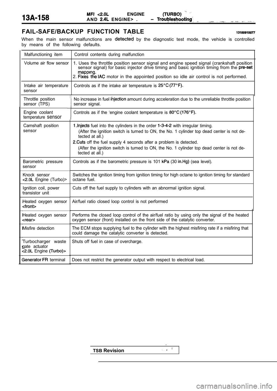
FAIL-SAFE/BACKUP FUNCTION TABLE
When the main sensor malfunctions are by the diagnostic test mode, the vehicle is controlled
by means of the following defaults.
Malfunctioning item Control contents during malfunct ion
Volume air flow sensor
1. Uses the throttle position sensor signal and eng ine speed signal (crankshaft position
sensor signal) for basic injector drive timing and basic ignition timing from the
2. motor in the appointed position so idle air contro l is not performed.
Intake air temperature
Controls as if the intake air temperature is
sensor
Throttle position
sensor (TPS)
Engine coolant
temperaturesensor
Camshaft position
sensor
Barometric pressure
sensor
Knock sensor
Engine (Turbo)>
Ignition coil, power
transistor unit
Heated oxygen sensor
Heated oxygen sensor
Misfire detection
Turbocharger waste
gate actuator Engine
terminal Performs the closed loop control of the air/fuel ra
tio by using only the signal of the heated
oxygen sensor (front) installed on the front side o f the catalytic converter.
The ECM stops supplying fuel to the cylinder with t he highest misfiring rate if a misfiring that
could damage the catalytic converter is detected.
Shuts off fuel in case of overcharge.
Does not restrict the generator output with respect to electrical load.
No increase in fuel amount during acceleration due to the unreliable throttle position
sensor signal.
Controls as if the ‘engine coolant temperature is
fuel into the cylinders in the order with irregular timing.
(After the ignition switch is turned to ON, the No. 1 cylinder top dead center is not de-
tected at all.)
off the fuel supply 4 seconds after a problem is d etected.
(After the ignition switch is turned to ON, the No. 1 cylinder top dead center is not de-
tected at all.)
Controls as if the barometric pressure is 101
(30 (sea level).
Switches the ignition timing from ignition timing f or high octane to ignition timing for standard
octane fuel.
Cuts off the fuel supply to cylinders with an abnor mal ignition signal.
Air/fuel ratio closed loop control is not performed
TSB Revision
Page 541 of 2103
ENGINE (TURBO)
AND
ENGINE> Troubleshooting
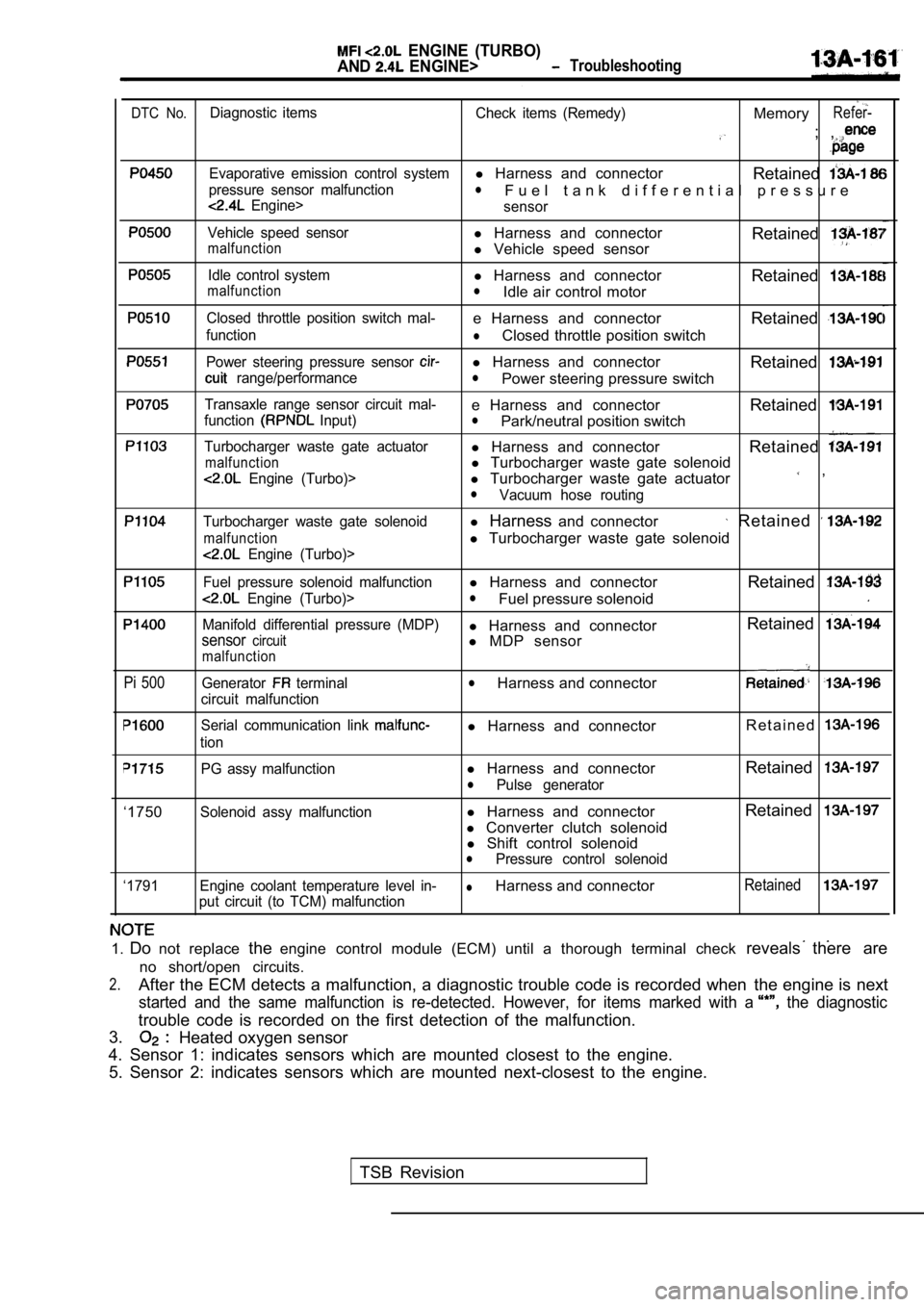
DTC No.Diagnostic items Check items (Remedy)MemoryRefer-
; ,
Evaporative emission control systeml Harness and connector
Retained
pressure sensor malfunctionl
Engine>F u e l t a n k d i f f e r e n t i a l p r e s s u r e
sensor
Vehicle speed sensorl Harness and connectormalfunctionl Vehicle speed sensor Retained
Idle control systeml
Harness and connector
RetainedmalfunctionlIdle air control motor
Closed throttle position switch mal-e Harness and connector Retained
functionlClosed throttle position switch
Power steering pressure sensor l Harness and connector
Retained
range/performancelPower steering pressure switch
Transaxle range sensor circuit mal-e Harness and connector Retainedfunction Input)lPark/neutral position switch
Turbocharger waste gate actuatorl Harness and connector
Retained
malfunctionl Turbocharger waste gate solenoid
Engine (Turbo)>l Turbocharger waste gate actuator ,
lVacuum hose routing
Turbocharger waste gate solenoidl Harness and connector Retained
malfunctionl Turbocharger waste gate solenoid
Engine (Turbo)>
Fuel pressure solenoid malfunctionl Harness and connector
Retained
Engine (Turbo)>lFuel pressure solenoid
Manifold differential pressure (MDP)l Harness and connector Retainedsensorcircuitl
MDP sensormalfunction
Pi 500Generator terminal
circuit malfunctionlHarness and connector
Serial communication link
tion
l Harness and connector R e t a i n e d
‘1750
‘1791PG assy malfunction
l
Harness and connector RetainedlPulse generator
Solenoid assy malfunction
l Harness and connector Retained
l
Converter clutch solenoid
l Shift control solenoid
lPressure control solenoid
Engine coolant temperature level in-
lHarness and connectorRetained
put circuit (to TCM) malfunction
1. Do not replace theengine control module (ECM) until a thorough termin al check reveals there are
no short/open circuits.
2.After the ECM detects a malfunction, a diagnostic t rouble code is recorded when the engine is next
started and the same malfunction is re-detected. Ho wever, for items marked with a the diagnostic
trouble code is recorded on the first detection of the malfunction.
3.
Heated oxygen sensor
4. Sensor 1: indicates sensors which are mounted cl osest to the engine.
5. Sensor 2: indicates sensors which are mounted ne xt-closest to the engine.
TSB Revision
Page 577 of 2103
ENGINE
AND ENGINE> Troubleshooting
NGCheck the following connectors: Repair
OK
Check trouble symptom.
NG
NGCheck the harness wire between the the transaxle control Repairmodule connector. ,
OK
There is probably a problem in automatic transaxle control
system. Carry out automatic transaxle troubleshooti ng.
(Refer to GROUP Troubleshooting)
OK
Replace the ECM.
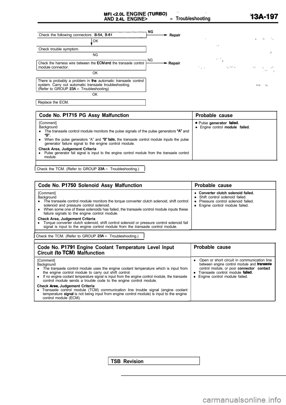
Code No. PG Assy Malfunction
Probable cause
[Comment] Pulse generatorBackgroundl Engine control module failed.lThe transaxle control module monitors the pulse sig nals of the pulse generators and
lWhen the pulse generators “A” and the transaxle control module inputs the pulsegenerator failure signal to the engine control modu le.
Check Area, Judgement Criteria
lPulse generator fail signal is input to the engine control module from the transaxle control
module.
Check the TCM. (Refer to GROUP Troubleshooting.)
Code No. Solenoid Assy Malfunction Probable cause
[Comment]
Background
lThe transaxle control module monitors the torque co nverter clutch solenoid, shift control
solenoid and pressure control solenoid.
lWhen some one of these solenoids has failed, the tr ansaxle control module inputs these
failure signals to the engine control module.
Check Area, Judgement Criteria
lTorque converter clutch solenoid, shift control sol enoid or pressure control solenoid fail
signal is input to the engine control module from t he transaxle control module.
Check the TCM. (Refer to GROUP Troubleshooting.)
l Converter clutch solenoid failed.l Shift control solenoid failed.
l Pressure control solenoid failed.
l Engine control module failed.
Code No. Engine Coolant Temperature Level Input
Circuit
Malfunction
[Comment]
Background
lThe transaxle control module uses the engine coolan t temperature which is input from
the engine control module to carry out shift contro l.
lIf no engine coolant temperature signal is input from the engine control module, the transaxlecontrol module sends a trouble code to the engine c ontrol module.
Check
Judgement Criteria
l Transaxle control module (TCM) communication line t rouble signal (engine coolant
temperature
is not being input from engine control module) is input to the engine
control module (ECM).
Probable cause
lOpen or short circuit in communication linebetween engine control module and control module, or poor connector contactl Transaxle control module l Engine control module failed.
TSB Revision
Page 697 of 2103
ENGINE COOLING On-vehicle Service
Engine (Turbo) and
ON-VEHICLE SERVICE
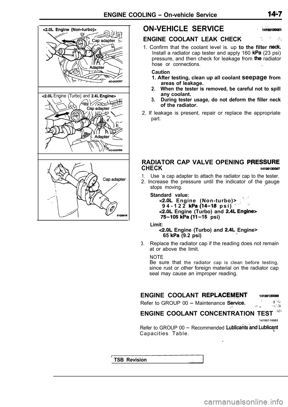
ENGINE COOLANT LEAK CHECK
1. Confirm that the coolant level is. up to the filter
Install a radiator cap tester and apply 160 (23 psi)
pressure, and then check for leakage from
radiator
hose or connections.
Caution
1. After testing, clean up all coolant seepagefrom
areas of leakage.
2.When the tester is removed, be careful not to spill
any coolant.
3.During tester usage, do not deform the filler neck
of the radiator.
2. If leakage is present, repair or replace the app ropriate
part.
RADIATOR CAP VALVE OPENING
CHECK
1.Use ‘a cap adapter to attach the radiator cap to the tester.
2. Increase the pressure until the indicator of the gauge
stops moving..
Standard value:
E n g i n e ( N o n - t u r b o ) >
9 4 - 1 2 2 p s i )
Engine (Turbo) and
psi)
Limit:
Engine (Turbo) and Engine>
65
(9.2 psi)
3.Replace the radiator cap if the reading does not re main
at or above the limit.
NOTE
Be sure that the radiator cap is clean before testing,
since rust or other foreign material on the radiato r cap
seal may cause an improper reading.
ENGINE COOLANT
Refer to GROUP 00 Maintenance
ENGINE COOLANT CONCENTRATION TEST
1 4 1 0 0 1 1 0 0 8 5
Refer to GROUP 00 Recommended
C a p a c i t i e s T a b l e . ,
TSB Revision
Page 731 of 2103
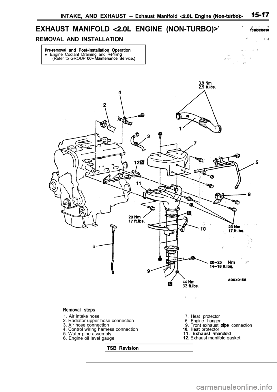
INTAKE, AND EXHAUST Exhaust Manifold Engine
EXHAUST MANIFOLD ENGINE (NON-TURBO)>’
REMOVAL AND INSTALLATION
and Post-installation Operationl Engine Coolant Draining and (Refer to GROUP
3.9 Nm2.9
6
Removal steps
1. Air intake hose
2. Radiator upper hose connection
3. Air hose connection
4. Control wiring harness connection
5. Water pipe assembly
6. Engine oil level gauge
Nm
44Nm33
,
7.Heat protector6.Engine hanger9. Front exhaust connection10.Heatprotector11. Exhaust 12. Exhaust manifold gasket
TSB RevisionI
Page 732 of 2103
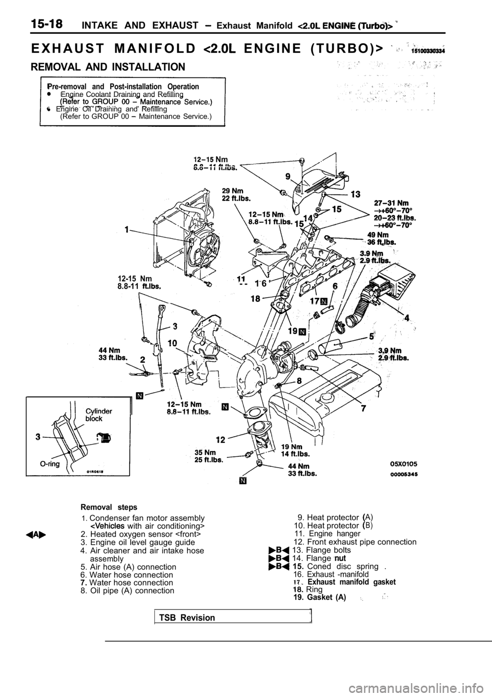
INTAKE AND EXHAUST Exhaust Manifold
E X H A U S T M A N I F O L D E N G I N E ( T U R B O ) >
REMOVAL AND INSTALLATION
Pre-removal and Post-installation OperationEngine Coolant Draining and Refilling
l Engine Oil Draining and Refilling
(Refer to GROUP 00
Maintenance Service.)
Nm
12-15 Nm8.8-11- - 1 6 ’
3
. .
Removal steps
1. Condenser fan motor assembly with air conditioning>
2. Heated oxygen sensor
3. Engine oil level gauge guide
4. Air cleaner and air intake hose
assembly5. Air hose (A) connection
6. Water hose connection
7. Water hose connection
8. Oil pipe (A) connection 9. Heat protector
A)
10. Heat protectorB)
11. Engine hanger
12. Front exhaust pipe connection 13. Flange bolts 14. Flange 15.
Coned disc spring .16. Exhaust -manifold17.Exhaust manifold gasket Ring19. Gasket (A)
TSB Revision
Page 820 of 2103
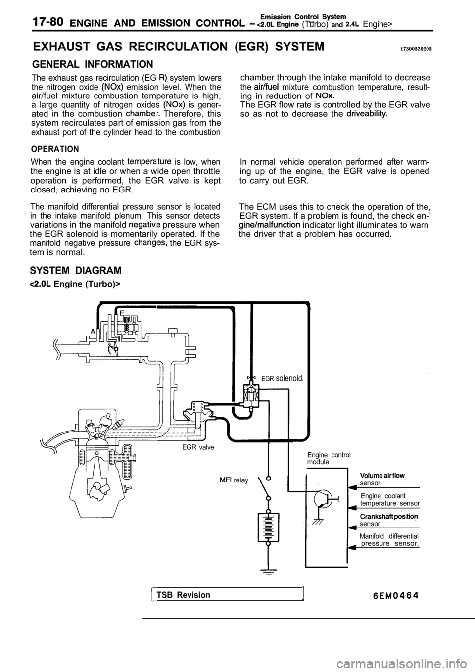
(Turbo) and Engine>
EXHAUST GAS RECIRCULATION
GENERAL INFORMATION
The exhaust gas recirculation (EG system lowers
the nitrogen oxide
emission level. When the
air/fuel mixture combustion temperature is high,
a large quantity of nitrogen oxides is gener-
ated in the combustion Therefore, this
system recirculates part of emission gas from the
exhaust port of the cylinder head to the combustion
OPERATION
When the engine coolant is low, when
the engine is at idle or when a wide open throttle
operation is performed, the EGR valve is kept
closed, achieving no EGR.
The manifold differential pressure sensor is locate d
in the intake manifold plenum. This sensor detects
variations in the manifold pressure when
the EGR solenoid is momentarily operated. If the
manifold negative pressure the EGR sys-
tem is normal.
SYSTEM DIAGRAM
Engine (Turbo)>
(EGR) SYSTEM17300520205
chamber through the intake manifold to decrease
the mixture combustion temperature, result-
ing in reduction of
The EGR flow rate is controlled by the EGR valve
so as not to decrease the
In normal vehicle operation performed after warm-
ing up of the engine, the EGR valve is opened
to carry out EGR.
The ECM uses this to check the operation of the, EGR system. If a problem is found, the check en-’
indicator light illuminates to warn
the driver that a problem has occurred.
EGR valve
relay
EGRsolenoid
Engine control
module
Isensor
Engine coolant
temperature sensor
sensor
Manifold differential
TSB Revision
pressure sensor,
Page 1072 of 2103
AUTOMATIC TRANSAXLE
ENGINE (TURBO) AND On-vehicle Service
Stall test consists of determining maximum engine speed
obtained at full throttle in positions. This test
checks torque converter overrunning clutch operation,
and holding ability of transmission clutches and
brake.
Caution
During this test, make sure no stands in front
of, or behind, vehicle.
1.Check the transmission fluid level, fluid temperatu re and
coolant temperature.
lFluid level: At “HOT” position on dipstick
l Fluid temperature:
lEngine coolant temperature:
2. Apply chocks to both rear wheels.
3.
engine tachometer.
4. Apply parking and service brakes fully.
5 . S t a r t e n g i n e .
6. With selector lever in position, depress accelerator
pedal fully to read engine
rpm. Do not hold
throttle wide open any longer than is necessary to obtain
maximum engine rpm reading, and never longer
5 seconds at a time. If more than one stall test is required,
operate at approximately 1,000 in neutral
for 2 minutes to cool transmission fluid between te sts.
Standard value:
TSB Revision
2,100 2,600
3 , 3 0 0 3 , 6 0 0
7.Place selector lever to position and perform test
by the same procedures above.
Stall Speed Above Specification in
If stall speed is higher than Specification, rear c lutch or overrun-
ning clutch is slipping. In this case, perform hydrau-
lic test to locate cause of slippage.
Stall Above Specification in “R”
If stall speed is higher than front clutch of trans-
axle or low-reverse brake is In this perform
hydraulic test to locate cause of slippage.
Stall Speed Above Specification and “R”
If stall speed is lower than insufficient engine
output or faulty torque converter is Check for en-
gine misfiring, ignition timing, valve clearance etc. If these
are good, torque converter is faulty..