1990 MITSUBISHI SPYDER air conditioning
[x] Cancel search: air conditioningPage 725 of 2103
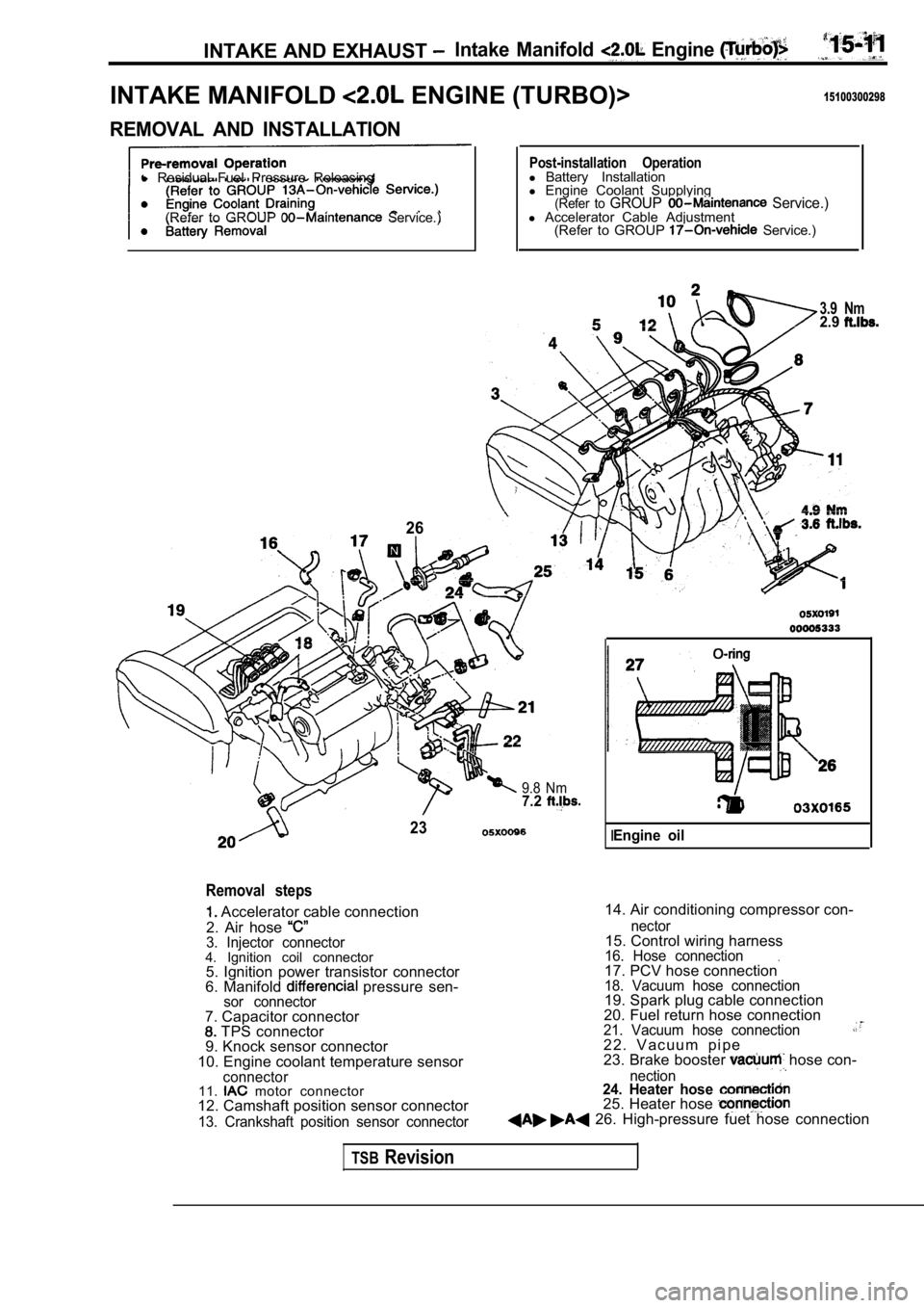
INTAKE AND EXHAUST Intake Manifold Engine
INTAKE MANIFOLD ENGINE (TURBO)>15100300298
REMOVAL AND INSTALLATION
l Residual Fuel Pressure Releasing
(Refer to GROUP
Service.)
26
Post-installation Operationl Battery Installation
l Engine Coolant Supplying
(Refer to GROUP Service.)l Accelerator Cable Adjustment
(Refer to GROUP Service.)
3.9 Nm2.9
9.8 Nm7.2
23
Removal steps
Accelerator cable connection
2. Air hose
3. Injector connector4. Ignition coil connector 5. Ignition power transistor connector
6. Manifold
pressure sen-sor connector
14. Air conditioning compressor con-
7. Capacitor connector
TPS connector
9. Knock sensor connector
10. Engine coolant temperature sensor
connector11. motor connector
12. Camshaft position sensor connector
13. Crankshaft position sensor connector nector
15. Control wiring harness16. Hose connection.17. PCV hose connection18. Vacuum hose connection19. Spark plug cable connection
20. Fuel return hose connection
21. Vacuum hose connection2 2 . V a c u u m p i p e
23. Brake booster hose con-
nection24. Heater hose 25. Heater hose 26. High-pressure fuet hose connection
IEngine oil
TSBRevision
Page 728 of 2103
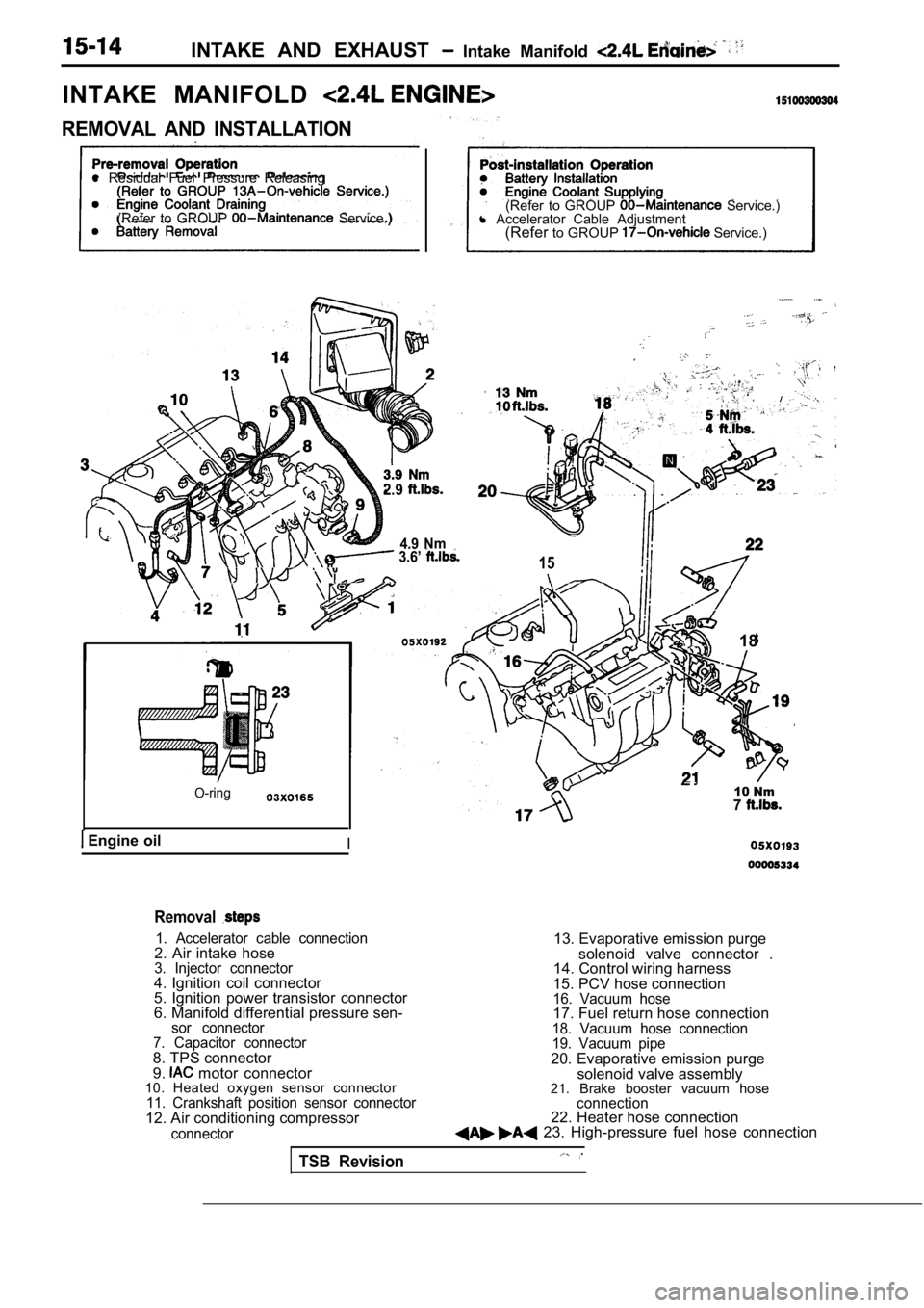
INTAKE AND EXHAUST Intake Manifold
INTAKE MANIFOLD
REMOVAL AND INSTALLATION
l Residual Fuel Pressure Releasing
(Refer to GROUP
Service.) (Refer to GROUP Service.)
l Accelerator Cable Adjustment
(Refer to GROUP
Service.)
2.9
4.9 Nm 3.6’ 15
O-ring
Engine oilI
18
10 Nm7
Removal
1. Accelerator cable connection2. Air intake hose3. Injector connector4. Ignition coil connector
5. Ignition power transistor connector
6. Manifold differential pressure sen-
sor connector
7. Capacitor connector
8. TPS connector
9. motor connector
10. Heated oxygen sensor connector
11. Crankshaft position sensor connector12. Air conditioning compressor
connector
13. Evaporative emission purge
solenoid valve connector .
14. Control wiring harness
15. PCV hose connection
16. Vacuum hose17. Fuel return hose connection18. Vacuum hose connection
19. Vacuum pipe
20. Evaporative emission purge solenoid valve assembly
21. Brake booster vacuum hose
connection22. Heater hose connection 23. High-pressure fuel hose connection
TSB Revision
Page 732 of 2103
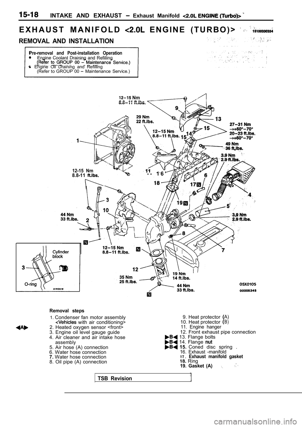
INTAKE AND EXHAUST Exhaust Manifold
E X H A U S T M A N I F O L D E N G I N E ( T U R B O ) >
REMOVAL AND INSTALLATION
Pre-removal and Post-installation OperationEngine Coolant Draining and Refilling
l Engine Oil Draining and Refilling
(Refer to GROUP 00
Maintenance Service.)
Nm
12-15 Nm8.8-11- - 1 6 ’
3
. .
Removal steps
1. Condenser fan motor assembly with air conditioning>
2. Heated oxygen sensor
3. Engine oil level gauge guide
4. Air cleaner and air intake hose
assembly5. Air hose (A) connection
6. Water hose connection
7. Water hose connection
8. Oil pipe (A) connection 9. Heat protector
A)
10. Heat protectorB)
11. Engine hanger
12. Front exhaust pipe connection 13. Flange bolts 14. Flange 15.
Coned disc spring .16. Exhaust -manifold17.Exhaust manifold gasket Ring19. Gasket (A)
TSB Revision
Page 741 of 2103

CONTENTS
AUTO-CRUISE CONTROL SYSTEM
. . . . . . . . . . . . . . . . . . . . . . . . . . . . . . . . . . . . .7
AUTO-CRUISE CONTROL* . . . . . . . . . . . . . . 40
GENERAL INFORMATION . . . . . . . . . . . . . . . . 7
ON-VEHICLE SERVICE. . . . . . . . . . . . . . . . . 33
Auto-cruise Control Cable Check and
Adjustment . . . . . . . . . . . . . . . . . . . . . . . . . . . . . .
33
Auto-cruise Control Component Check . . . . . 37
Auto-cruise Control System Operation Check
. . . . . . . . . . . . . . . . . . . . . . . . . . . . . . . . . . . . . . . . .
35
SERVICE SPECIFICATIONS . . . . . . . . . . . . . 8
SPECIAL TOOLS . . . . . . . . . . . . . . . . . . . . . . . . 8
TROUBLESHOOTING
ENGINE (NON-TURBO)> . . . . . . . . . . . 9
TROUBLESHOOTING
(TURBO) AND ENGINE> . . . . .
EMISSION CONTROL’ SYSTEM
. . . . .
CATALYTIC . . . . . . . . . . . . . .
General Information . . . . . . . . . . . . . . . . . . 57
EVAPORATIVE EMISSION .
SYSTEM. . . . . . . . . . . . . . . .
Air Conditioning . . . . . . . . . . . . . . . . . . . 52
Component Location
. . . . . . . . . . . . . . . . . .
Engine Coolant Temperature Sensor
Intake Air Temperature Sensor . . . . . . . . . . . . 52
WARNINGS REGARDING SERVICING OF SUPPLEMENTAL RESTRA INT SYSTEM (SRS) EQUIPPED
WARNING!
(1) Improper serviceor maintenance of any component of the or any SRS-related can to injuryorcleathtoservicepersonnel (from inadvertentfiring the SRS inoperative).
(2) Service or maintenance of any SRS component or SRS-related component must be performed only
MITSUBISHI dealer.
(3) MITSUBISHI dealer personnel must thoroughly rev iew this manual, and especially its GROUP
Restraint System (SRS) and GROUP 00 Maintenance Service, before any service or maintenance of any
componentof the SRS or any SRS-related component.
NOTEJhe includes the following components: warning light, air bag module, clock components (that may have to be removed/installed in connection with or areIndicated in the table of contents by an asterisk
Page 742 of 2103
17-2
Evaporative Emission Canister/Air Filter/
Evaporative Emission Ventilation Solenoid
. . . . . . . . . . . . . . . . . . . . . . . . . . . . . . . . . . . . . . . . .53
Evaporative Emission Purge Solenoid
Check. . . . . . . . . . . . . . . . .. . . . . . . . . . . . . . . . . . .
General Information. . .. . .. . . . . . . . . . . . . . .
Purge Control System Check. . . . . . . . . . . . .
Purge Port Vacuum Check. . . . . . . . . . . . . . . .51
EXHAUST GAS (EGR)
SYSTEM. . . . . . . . . . . . . . . . . . . . . . . . . . . . . . . 54
Component Location. . . . . . . . . . . . . . . . . . . . .54
EGR Port Vacuum Check. . . . . . . . . . . . . . . . .56
EGR System Check. . . . . . . . . . . . . . . . . . . . . .55
EGR Valve Check. . . . . . . . . . . . . . . . . . . . . . . .55
Electric EGR Transducer Solenoid Check
. . . . . . . . . . . . . . . . . . . . . . . . . . . . . . . . . . . . . . . . .
56
General Information. . . . . . . . . . . . . . . . . . . . . .54
GENERAL INFORMATION. . . . . . . . . . . . . . .44
POSITIVE CRANKCASE VENTILATION
SYSTEM. . . . . . . . . . . . . . . . . . . . . . . . . . . . . . . 48
Component Location. . . . . . . . . . . . . . . . . . . . .48
Crankcase Ventilation System Check. . . . . .49
General Information. . . . . . . . . . . . . . . . . . . . . .48
Positive Crankcase Ventilation Valve
Check. . . . . . . . . . . . . . . . . . . . . . . . . . . . . . . . . . .49
SERVICE SPECIFICATIONS. . . . . . . . . . . . .45
TROUBLESHOOTING’
. . . . . . . . . . . . . . . . . . .45
VACUUM HOSES. . . . . . . . . . . . . . . . . . . . . ..4 8
Vacuum Circuit Diagram. . . . . . . . . . . . . . . . . .47
Vacuum Hose Routing
. . . . . . . . . . . . . . . . . . . .46
CONTROL SYSTEM
ENGINE (TURBO) AND
ENGINE>. . . . . . . . . . . . . . . . . . . . . 6 0
CATALYTIC CONVERTER. . . . . . . . . . . . . . .89
General Information. . . . . . . . . . . . . . . . . . . . . .89
EVAPORATIVE EMISSION CONTROL
SYSTEM. . . . . . . . . . . . . . . . . . . . . . . . . . . . . . .69’
Air Conditioning Switch
. . . . . . . . . . . . . . . . . . .77
Component Location Engine (Turbo)>
. . . . . . . . . . . . . . . . . . . . . . . . . . . . . . . . . . . . . . . . .
69
Component Location Engine (Turbo)>
. . . . . . . . . . . . . . . . . . . . . . . . . . . . . . . . . . . . . . . . .
70
Evaporative Emission Canister/Fuel Tank
Pressure Relief Valve/Purge Control Valve
. . . . . . . . . . . . . . . . . . . . . . . . . . . . . . . . . . . . . . . . .78
Evaporative Emission Purge Solenoid
Check. . . . . . . . . . . . . . . . . . . . . . . . . . . . . . . . . . .76
General Information Engine (Turbo)> G e n e r a l I n f o r m a t i o n
. . . . . . . . . . . . . . . . . .
. . . . . . . . . . . . . . . . . . . . . . .70
Purge Control System Check
. . . . . . . . . . . . . . . . . . . . . . . . . .. . . . . . . . . . . . . . . .71
Purge Control ‘System
(Purge Flow Check) Engine>. . . . . . .73
Purge Control Engine (Turbo)>
. . . . . . . . . . . . . . . . . . . . . . . . . . . . . . . . . . . . . . . . . .
Purge Port Vacuum Check. . . . . . . . . . . . . . . .75
Volume Air Flow Sensor, Engine Coolant
Temperature Sensor and Intake Air
Temperature Sensor. . . . . . . . . . . . . . . . . . . . . . .77
RECIRCULATION (EGR)
.... . .. . . . . . . . . . . . . . . . . . . . . . . .81
Component Location. . . . . . . . . . . . . . . . . . . . .82
EGR Port Vacuum Check . . . . . . . . . . . . . . . . .86
EGR Solenoid Check Engine (Turbo)>
. . . . . . . . . . . . . . . . . . . . . . . . . . . . . . . . . . . . . . . . .
87
EGR Solenoid Check Engine>. . . . . .
EGR System Check . . . . . . . . . . . . . . . . . .
EGR Valve Check. . . . . . . . . . . . .. . .
General Information... . . . . . . . . . . . . .....81
Vacuum Control Valve Check
. . . . . . . . .
.......................................
POSITIVE CRANKCASE VENTILATION
SYSTEM
. . . . . . . ... . .. . . . . . . . . . . . . . . . . 65
Component Location. . . . . . . . . . . . .. . . . . . . . .66
Crankcase Ventilation. System . .67
General Information
. . . .. . . . . ... . ........
Positive Crankcase Ventilation Valve
Check. . . . . . . . . . . . . . . . . . . . . ... . ............
SERVICE SPECIFICATIONS. .. . . . . . . . . 60
SPECIAL TOOL . . . . . . . . . . . . . . . . . . . . . . .
. . .. .
HOSES
. . . . ..
. . . . . . . . . . . . . . . . . . . . .,
Circuit Diagram.. . . . . . . . . . . . . . . . . . ,
Vacuum Hose Routing. . . . . . . ...... . . . 6 1
ENGINE CONTROL
3
ACCELERATOR
......
GENERAL INFORMATION . . . . . .. . . . . . . . . .3
ON-VEHICLE SERVICE. . . . . . . . . . . .4
Accelerator Cable Check and
Adjustment. . . . . . . . . . . . . . . . . . . . . . . . . . . . . . .
SERVICE SPECIFICATION. . . . . . . . . . . . . . .3
. ... . . . . ...3. . . . . . . . . . . . . . . . . . . . . . . . . . . . . . . . . . . . . . . . .
69
Page 792 of 2103
ENGINE AND EMISSION CONTROL
ENGINE COOLANT TEMPERATURE SENSOR
AND INTAKE AIR TEMPERATURE SENSOR
To check these parts, refer to GROUP Troubleshooting.
AIR CONDITIONING SWITCH17300200031
To check the air conditioning switch, refer to GROU P 55
Air Conditioning Switch.
TSB Revision
Page 816 of 2103
AND C O N T R O L (Turbo) and Engine>
Valve
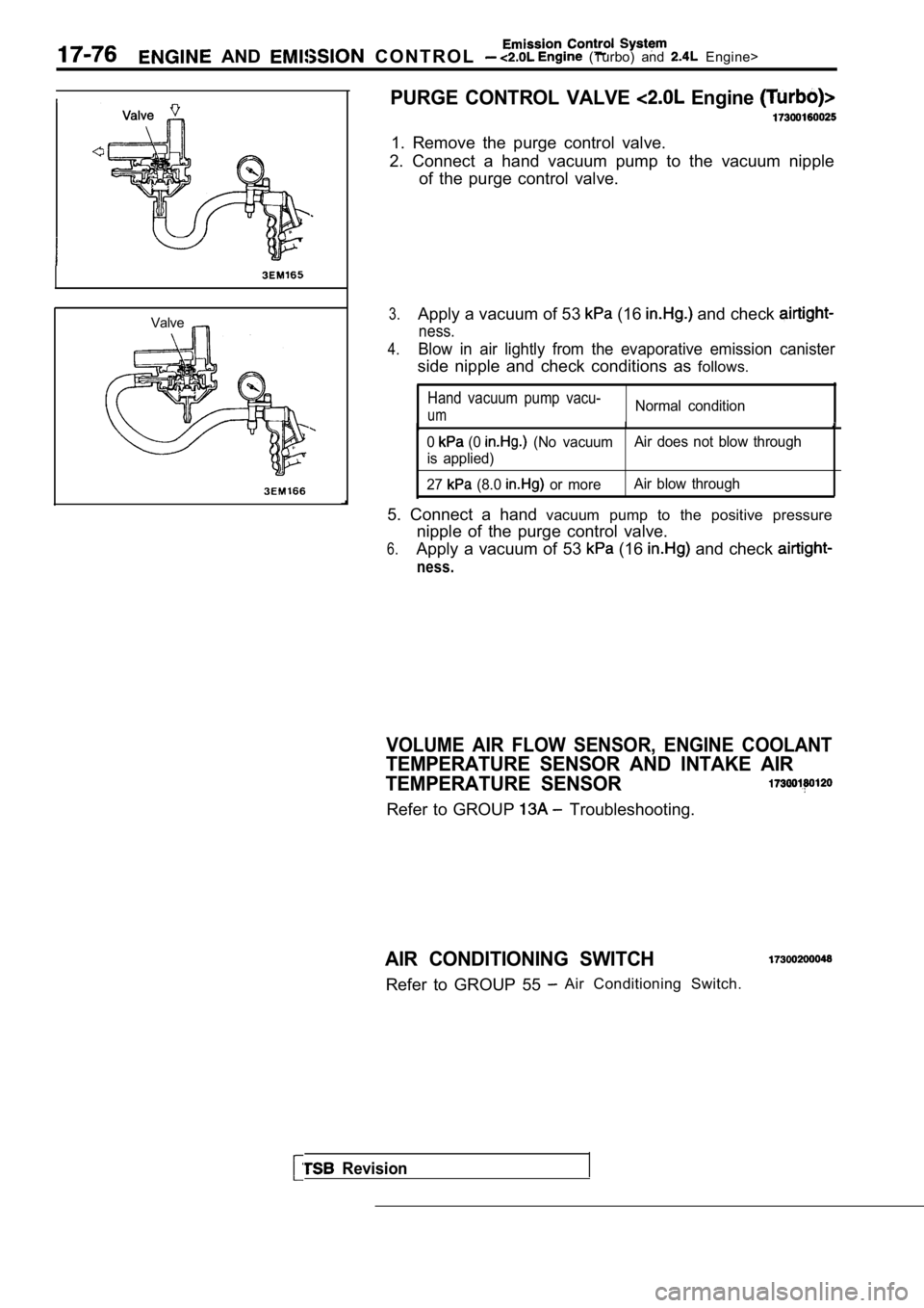
PURGE CONTROL VALVE Engine
1. Remove the purge control valve.
2. Connect a hand vacuum pump to the vacuum nipple of the purge control valve.
3.Apply a vacuum of 53 (16 and check
ness.
4.Blow in air lightly from the evaporative emission c anister
side nipple and check conditions as follows.
Hand vacuum pump vacu-
umNormal condition
0 (0 (No vacuumAir does not blow through
is applied)
27
(8.0 or more Air blow through
5. Connect a hand
vacuum pump to the positive pressure
nipple of the purge control valve.
6.Apply a vacuum of 53 (16 and check
ness.
Revision
VOLUME AIR FLOW SENSOR, ENGINE COOLANT
TEMPERATURE SENSOR AND INTAKE AIR
TEMPERATURE SENSOR
Refer to GROUP Troubleshooting.
AIR CONDITIONING SWITCH
Refer to GROUP 55 Air Conditioning Switch.
Page 1070 of 2103
AUTOMATIC TRANSAXLE
ENGINE (TURBO) AND ENGINE> On-vehicle Service
Revision
S E R V O S W I T C H C H E C K
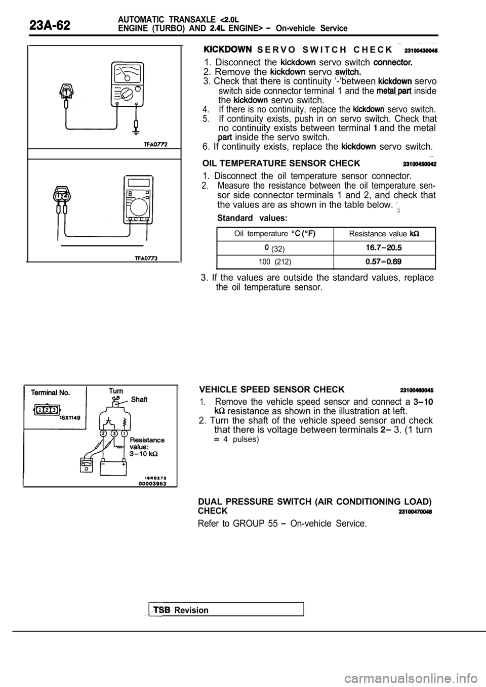
1. Disconnect the servo switch
2. Remove the servo
3. Check that there is continuity ‘-‘between servo
switch side connector terminal 1 and the inside
the servo switch.
4.If there is no continuity, replace the servo switch.
5.If continuity exists, push in on servo switch. Check that
no continuity exists between terminal and the metal
inside the servo switch.
6. If continuity exists, replace the
servo switch.
OIL TEMPERATURE SENSOR CHECK
1. Disconnect the oil temperature sensor connector.
2.Measure the resistance between the oil temperature sen-
sor side connector terminals 1 and 2, and check that
the values are as shown in the table below.
Standard values:
Oil temperature Resistance value
(32)
100 (212)
3. If the values are outside the standard values, r eplace
the oil temperature sensor.
VEHICLE SPEED SENSOR CHECK
1.Remove the vehicle speed sensor and connect a
resistance as shown in the illustration at left.
2. Turn the shaft of the vehicle speed sensor and c heck
that there is voltage between terminals 3. (1 turn
4 pulses)
DUAL PRESSURE SWITCH (AIR CONDITIONING LOAD)
CHECK
Refer to GROUP 55 On-vehicle Service.