Page 632 of 2103
ENGINE (TURBO)
AND ENGINE> Troubleshooting
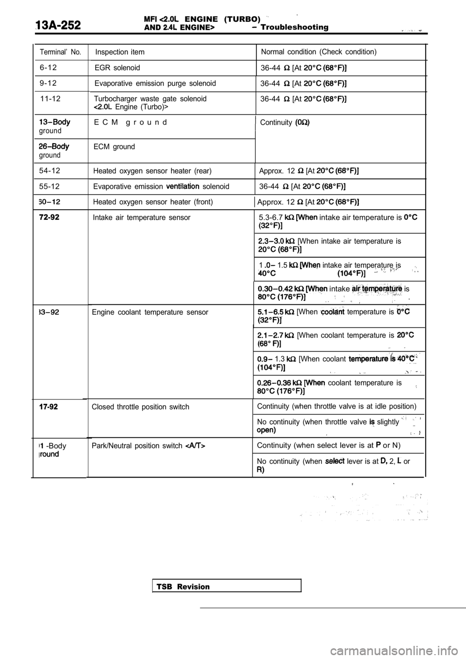
Terminal’ No.
6 - 1 2
9 - 1 2 11-12
ground
ground
54-12
55-12
72-92
17-92
-Body
Inspection item
EGR solenoid Normal condition (Check condition)
36-44 [At
Evaporative emission purge solenoid
Turbocharger waste gate solenoid
Engine (Turbo)>
36-44 [At
36-44 [At
E C M g r o u n dContinuity
ECM ground
Heated oxygen sensor heater (rear)
Evaporative emission
solenoid Approx. 12
[At
36-44 [At
Heated oxygen sensor heater (front) Approx. 12 [At
Intake air temperature sensor5.3-6.7 intake air temperature is
[When intake air temperature is
1 1.5 intake air temperature is
Engine coolant temperature sensor
intake is
.
[When temperature is
[When coolant temperature is
1.3 [When coolant
coolant temperature is
TSB Revision
Closed throttle position switch
Continuity (when throttle valve is at idle position
)
No continuity (when throttle valve
slightly
Park/Neutral position switch Continuity (when select lever is at or N)
No continuity (when lever is at 2, or
Page 642 of 2103
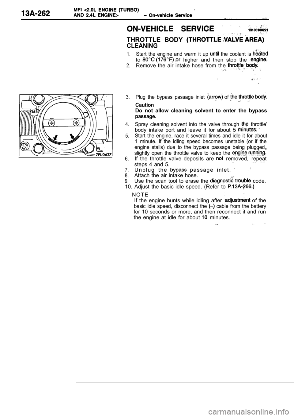
THROTTLE BODY
CLEANING
1.
2.
Start the engine and warm it up the coolant is
to higher and then stop the
Remove the air intake hose from the
.
3.
4.
5.
6.
7.
8.
9.
Plug the bypass passage inlet of
Caution
Do not allow cleaning solvent to enter the bypass
passage.
Spray cleaning solvent into the valve through throttle’
body intake port and leave it for about 5
Start the engine, race it several times and idle it for about
1 minute. If the idling speed becomes unstable (or if the
engine stalls) due to the bypass passage being plug ged,,
slightly open the throttle valve to keep the
If the throttle valve deposits are removed, repeat
steps 4 and 5.
U n p l u g t h e p a s s a g e i n l e t .
Attach the air intake hose.
Use the scan tool to erase the
code.
10. Adjust the basic idle speed. (Refer to
N O T E If the engine hunts while idling after
of the
basic idle speed, disconnect the cable from the battery
for 10 seconds or more, and then reconnect it and r un
the engine at idle for about
minutes.
Page 646 of 2103
SPEED
NOTE
1.The standard idle speed by,
engine speed the
and there should usually for readjustment.
2. The adjustment, after first:
confirming that the spark plugs; the
air control servo, the compression pressure,
all normal.
1.. The vehicle should be prepared as follows before the
i n s p e c t i o n a n d a d j u s t m e n t .
lEngine coolant temperature:
l Lights, cooling fan and accessories: OFF
‘2.
l Transaxle: Neutral (A/T for range)
Connect the scan tool to the data link connector
N O T E
When the scan tool is connected, the diagnostic tes t mode
control terminal should be grounded.
3. Start the engine and run at idle.
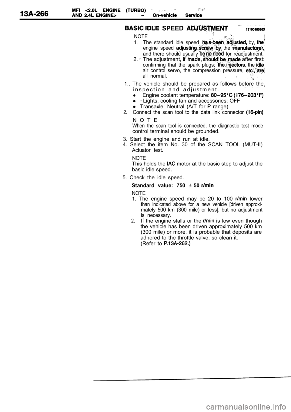
4. Select the item No. 30 of the SCAN TOOL (MUT-II)
Actuator test.
NOTE
This holds the motor at the basic step to adjust the
basic idle speed.
5. Check the idle speed. Standard value: 750
50
NOTE
1. The engine speed may be 20 to 100 lower
than indicated above for a new vehicle [driven appr oxi-
mately 500 km (300 mile) or less], but no adjustment
is necessary.
2.If the engine stalls or the is low even though
the vehicle has been driven approximately 500 km (300 mile) or more, it is probable that deposits ar e
adhered to the throttle valve, so clean it. (Refer to
Page 649 of 2103
AND On-vehicle
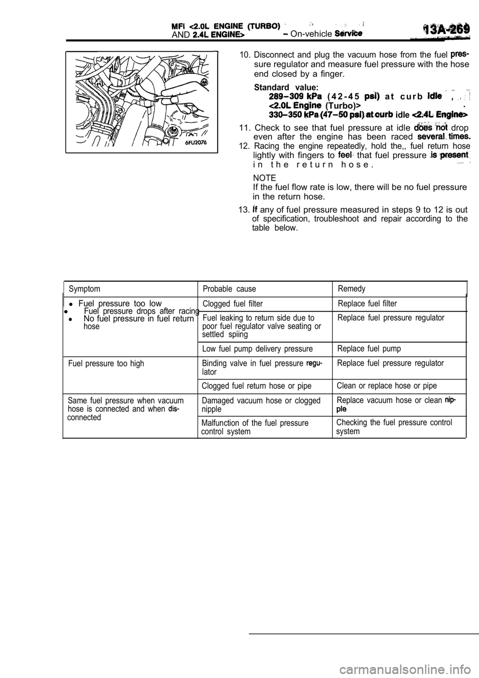
10. Disconnect and plug the vacuum hose from the fuel
sure regulator and measure fuel pressure with the hose
end closed by a finger.
Standard value:
( 4 2 - 4 5 a t c u r b ,
(Turbo)> .
idle
11. Check to see that fuel pressure at idle drop
even after the engine has been raced
12. Racing the engine repeatedly, hold the,, fuel r eturn hose
lightly with fingers to that fuel pressure
i n t h e r e t u r n h o s e .
NOTE
If the fuel flow rate is low, there will be no fuel pressure
in the return hose.
13.
any of fuel pressure measured in steps 9 to 12 is out
of specification, troubleshoot and repair according to the
table below.
Symptom Probable cause Remedy
l Fuel pressure too lowClogged fuel filterReplace fuel filterlFuel pressure drops after racinglNo fuel pressure in fuel returnFuel leaking to return side due toReplace fuel pressure regulator
hose poor fuel regulator valve seating or
settled spiing
Low fuel pump delivery pressure Replace fuel pump
Fuel pressure too high Binding valve in fuel pressure
Replace fuel pressure regulator
lator
Same fuel pressure when vacuum
hose is connected and when
connected Clogged fuel return hose or pipe
Clean or replace hose or pipe
Damaged vacuum hose or clogged Replace vacuum hose or clean
nipple
Malfunction of the fuel pressureChecking the fuel pressure control
control system system
Page 666 of 2103
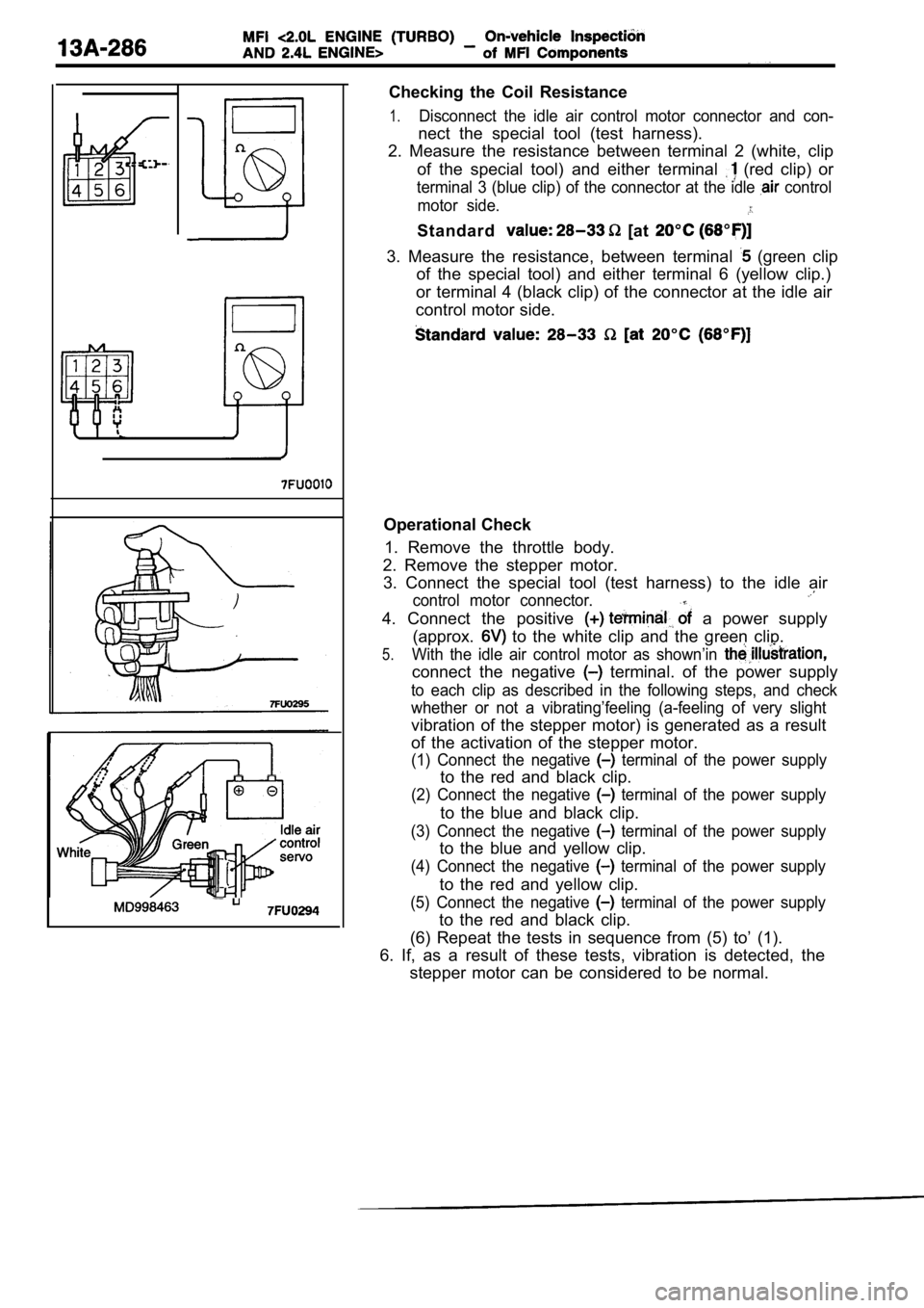
Checking the Coil Resistance
1.Disconnect the idle air control motor connector and con-
nect the special tool (test harness).
2. Measure the resistance between terminal 2 (white , clip
of the special tool) and either terminal
(red clip) or
terminal 3 (blue clip) of the connector at the idle control
motor side.
Standard [at
3. Measure the resistance, between terminal (green clip
of the special tool) and either terminal 6 (yellow clip.)
or terminal 4 (black clip) of the connector at the idle air
control motor side.
Operational Check
1. Remove the throttle body.
2. Remove the stepper motor. 3. Connect the special tool (test harness) to the i dle air
control motor connector.
4. Connect the positive a power supply
(approx.
to the white clip and the green clip.
5.With the idle air control motor as shown’in
connect the negative terminal. of the power supply
to each clip as described in the following steps, a nd check
whether or not a vibrating’feeling (a-feeling of ve ry slight
vibration of the stepper motor) is generated as a r esult
of the activation of the stepper motor.
(1) Connect the negative terminal of the power supply
to the red and black clip.
(2) Connect the negative terminal of the power supply
to the blue and black clip.
(3) Connect the negative terminal of the power supply
to the blue and yellow clip.
(4) Connect the negative terminal of the power supply
to the red and yellow clip.
(5) Connect the negative terminal of the power supply
to the red and black clip.
(6) Repeat the tests in sequence from (5) to’ (1).
6. If, as a result of these tests, vibration is det ected, the
stepper motor can be considered to be normal.
Page 684 of 2103
FUEL SUPPLY Fuel Tank
Fuel gauge unit and
pipe assembly
Front of
Mating marks
Fuel gauge unit and
pump assembly
Mating marks
INSTALLATION SERVICE POINT
INSTALLATION ,
Use the special tool to tighten the the
so that the marks on the fuel tank the, unit
and pump assembly (or the fuel gauge and pipe assembly)
are aligned.
Caution
Make sure that the fuel gauge unit and pump assembl y
(or the fuel gauge unit and pipe assembly) does not turn
together with the cap when tightening the cap.
If the mating marks are not aligned, the position o f the
float will not be correct and the fuel gauge indicator light
and the fuel level gauge will properly.
FUEL TANK DIFFERENTIAL PRESSURE SENSOR
INSTALLATION
Caution
When removing or installing the sensor, take care n ot
to damage sealing.
TSB Revision
Page 687 of 2103
F U E L S U P P L Y Fuel
Fuel gauge unit and
pipe assembly
Mating marks
Fuel gauge unit and
pump assembly
Mating marks
0 0 0 0 5 3 3 0
(7) After applying soapy water
fuel tank. Use the special tool to ,
specified torque so
the fuel
the fuel gauge unit and pump assembly (or
unit and pipe assembly) are aligned.
Caution
Make sure that the fuel gauge unit and
(or the fuel gauge unit and does not
turn together with the cap ‘when
cap.
If the
marks the of
the float will
light and the fuel
Caution
The packing should be as in the
illustration.
(8) Check for leaks from the installation section o f the
gauge unit and pump assembly or the fuel gauge
and pipe assembly by procedure.
1.Apply soapy water to the circumference of the cap.
2. Choke the vapor hose
main apply a n
internal pressure of 10
or less
the return hose and check to be that no bu
f o r m i n t h e s o a p y
TSB Revision
Page 741 of 2103

CONTENTS
AUTO-CRUISE CONTROL SYSTEM
. . . . . . . . . . . . . . . . . . . . . . . . . . . . . . . . . . . . .7
AUTO-CRUISE CONTROL* . . . . . . . . . . . . . . 40
GENERAL INFORMATION . . . . . . . . . . . . . . . . 7
ON-VEHICLE SERVICE. . . . . . . . . . . . . . . . . 33
Auto-cruise Control Cable Check and
Adjustment . . . . . . . . . . . . . . . . . . . . . . . . . . . . . .
33
Auto-cruise Control Component Check . . . . . 37
Auto-cruise Control System Operation Check
. . . . . . . . . . . . . . . . . . . . . . . . . . . . . . . . . . . . . . . . .
35
SERVICE SPECIFICATIONS . . . . . . . . . . . . . 8
SPECIAL TOOLS . . . . . . . . . . . . . . . . . . . . . . . . 8
TROUBLESHOOTING
ENGINE (NON-TURBO)> . . . . . . . . . . . 9
TROUBLESHOOTING
(TURBO) AND ENGINE> . . . . .
EMISSION CONTROL’ SYSTEM
. . . . .
CATALYTIC . . . . . . . . . . . . . .
General Information . . . . . . . . . . . . . . . . . . 57
EVAPORATIVE EMISSION .
SYSTEM. . . . . . . . . . . . . . . .
Air Conditioning . . . . . . . . . . . . . . . . . . . 52
Component Location
. . . . . . . . . . . . . . . . . .
Engine Coolant Temperature Sensor
Intake Air Temperature Sensor . . . . . . . . . . . . 52
WARNINGS REGARDING SERVICING OF SUPPLEMENTAL RESTRA INT SYSTEM (SRS) EQUIPPED
WARNING!
(1) Improper serviceor maintenance of any component of the or any SRS-related can to injuryorcleathtoservicepersonnel (from inadvertentfiring the SRS inoperative).
(2) Service or maintenance of any SRS component or SRS-related component must be performed only
MITSUBISHI dealer.
(3) MITSUBISHI dealer personnel must thoroughly rev iew this manual, and especially its GROUP
Restraint System (SRS) and GROUP 00 Maintenance Service, before any service or maintenance of any
componentof the SRS or any SRS-related component.
NOTEJhe includes the following components: warning light, air bag module, clock components (that may have to be removed/installed in connection with or areIndicated in the table of contents by an asterisk