Page 819 of 2103
Evaporative
emission
canister side
Rubber hose
F U E L T A N K ,
I N S T A L L A T I O N
Install the fuel relief
on the left.,
,
I..- ,
I N S P E C T I O N
FUEL TANK PRESSURE RELIEF VALVE SIMPLE .,
WARNING
To avoid bodily injury, do not breathe fuel
Attach a clean hose and tank
Inspection procedure,
Lightly blow from inlet A i r p a s s e s
(fuel tank side).slight feeling of
Lightly blow from outlet side.Air
resistance, , .
EVAPORATIVE EMISSION VENTILATION SOLENOID
CHECK
(1) Connect a hand vacuum pump to nipple (A) of the
solenoid.
Check airtightness by applying a vacuum with voltag e
applied directly from the ‘battery to
evaporative
emission ventilation solenoid. and
(3) Measure the resistance between the terminals of the
solenoid.
Standard value: 17-21 (at
TSB Revision
Page 820 of 2103

(Turbo) and Engine>
EXHAUST GAS RECIRCULATION
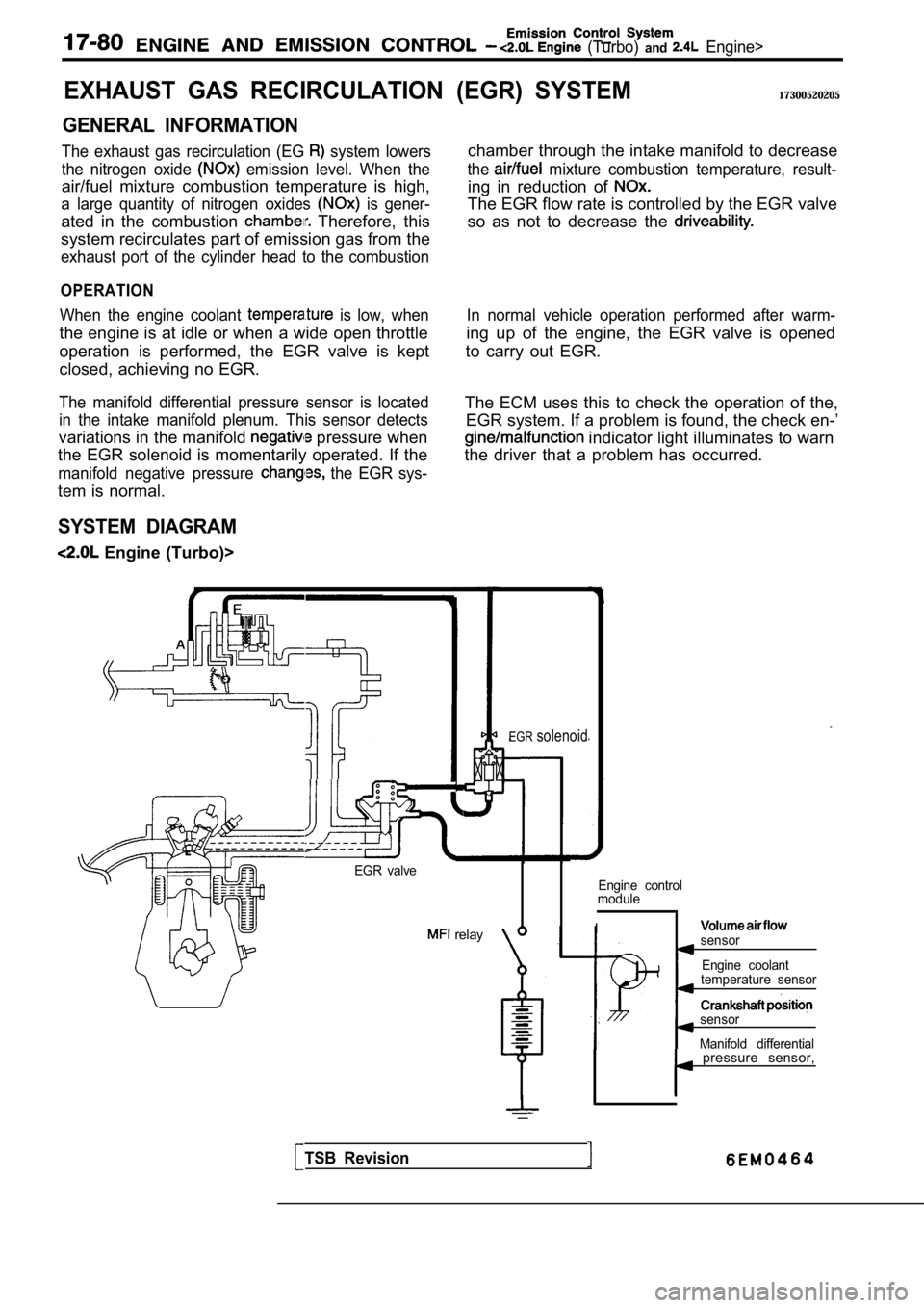
GENERAL INFORMATION
The exhaust gas recirculation (EG system lowers
the nitrogen oxide
emission level. When the
air/fuel mixture combustion temperature is high,
a large quantity of nitrogen oxides is gener-
ated in the combustion Therefore, this
system recirculates part of emission gas from the
exhaust port of the cylinder head to the combustion
OPERATION
When the engine coolant is low, when
the engine is at idle or when a wide open throttle
operation is performed, the EGR valve is kept
closed, achieving no EGR.
The manifold differential pressure sensor is locate d
in the intake manifold plenum. This sensor detects
variations in the manifold pressure when
the EGR solenoid is momentarily operated. If the
manifold negative pressure the EGR sys-
tem is normal.
SYSTEM DIAGRAM
Engine (Turbo)>
(EGR) SYSTEM17300520205
chamber through the intake manifold to decrease
the mixture combustion temperature, result-
ing in reduction of
The EGR flow rate is controlled by the EGR valve
so as not to decrease the
In normal vehicle operation performed after warm-
ing up of the engine, the EGR valve is opened
to carry out EGR.
The ECM uses this to check the operation of the, EGR system. If a problem is found, the check en-’
indicator light illuminates to warn
the driver that a problem has occurred.
EGR valve
relay
EGRsolenoid
Engine control
module
Isensor
Engine coolant
temperature sensor
sensor
Manifold differential
TSB Revision
pressure sensor,
Page 859 of 2103

CONTENTS
MANUAL TRANSAXLE ENGINEMANUAL TRANSAXLE ENGINE
(NON-TURBO)>(TURBO) AND ENGINE>
GENERAL INFORMATION . . . . . . . . . . . . . . 22GENERAL INFORMATION . . . . . . . . . . . . . . . .
2
LUBRICANTS. . . . . . . . . . . . . . . . . . . . . . . . . . 24LUBRICANTS. . . . . . . . . . . . . . . . . . . . . . . . . . .6
ON-VEHICLE SERVICE. . . . . . . . . . . . . . . . .
2 4
Transaxle Oil Level Check . . . . . . . . . . . . . . . .
24
Transaxle Oil Replacement . . . . . . . . . . . . . . .
24
SERVICE SPECIFICATIONS. . . . . . . . . . . . .24
SPECIAL TOOLS. . . . . . . . . . . . . . . . . . . . . . .24
TRANSAXLE ASSEMBLY. . . . . . . . . . . . . . .28
TRANSAXLE CONTROL*. . . . . . . . . . . . . . . .25ON-VEHICLE SERVICE
. . . . . . . . . . . . . . . . 8
Shift Lever Assembly
. . . . . . . . . . . . . . . . . . . . .
27
TROUBLESHOOTING. . . . . . . . . . . . . . . . . . .24
Transaxle Oil Level Check . . . . . . . . . . . . . . . . .8
Transaxle Oil Replacement
. . . . . . . . . . .. . .
Transfer Oil Level Check ...... . . . . . . . . . . .
Transfer Oil Replacement. . . . . . . . . . . . . . . . . .8
SERVICE SPECIFICATIONS. . . . . . . . . . ...
SPECIAL TOOLS 7. . . . . . . . . . . . . . . . . .
TRANSAXLE ASSEMBLY
. . . . . . . . . . . . . . . . . . . . ... . . .
. . . . . . . . . . . . . . . . . . . . . . . . . . . .
. . 1 2
TRANSAXLE CONTROL*... . . . . . . . .
Shift Lever Assembly. . . . . . . . . . . . . . . . . . . . . .1 1
TRANSFER ASSEMBLY . . . . . . . .
TROUBLESHOOTING . . . . . . . . . . . . . . . . . .
WARNINGS REGARDING SERVICING OF SUPPLEMENTAL RESTRA
INT SYSTEM (SRS) EQUIPPED VEHICLES
WARNING!
(1)Improper service or maintenance of any component of the or any component, can lead to personalinjury or death to service personnel (from inadvertent firing of the air bag) or to the driver and passenger (from
rendering the inoperative).Service or maintenance of any or component must be performed only at an authorized MITSUBISHI dealer.(3)MITSUBISHI dealer personnel must thoroughly review this manual,and especially its GROUP
Restraint System and GROUP 00 Maintenance Service, before beginning any or maintenance of
any component of the or any component.
NOTEThe SRS includes the following components: warning light, air bag module,clock spring, and interconnecting
wiring. Other
components (that may have to be removed/installed in connection with service or maintenance)
are indicated in the table of contents by an asterisk
Page 870 of 2103

MANUAL TRANSAXLE
ENGINE AND ENGINE> Transaxle
TRANSAXLE
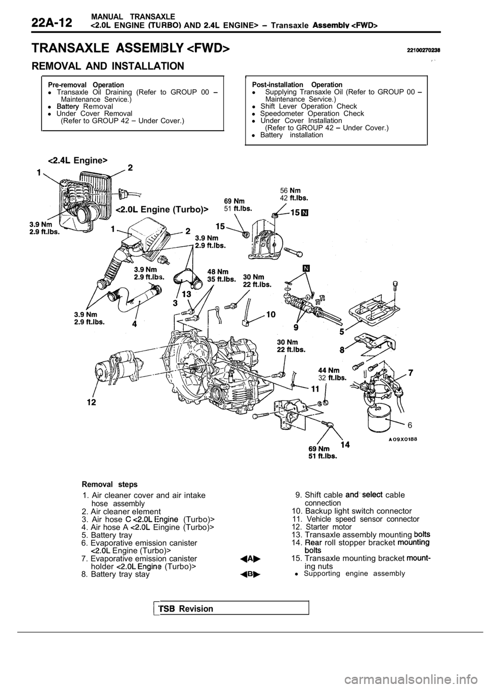
REMOVAL AND INSTALLATION
Pre-removal Operationl Transaxle Oil Draining (Refer to GROUP 00 Maintenance Service.)l Removal
l Under Cover Removal
(Refer to GROUP 42
Under Cover.)
Engine>
Post-installation Operationl Supplying Transaxle Oil (Refer to GROUP 00 Maintenance Service.)l Shift Lever Operation Check
l Speedometer Operation Check
l Under Cover Installation
(Refer to GROUP 42
Under Cover.)
l Battery installation
56
6942
Engine (Turbo)>51
32
6
Removal steps
1. Air cleaner cover and air intake
hose assembly2. Air cleaner element
3. Air hose (Turbo)>
4. Air hose A Eingine (Turbo)>
5. Battery tray
6. Evaporative emission canister
Engine (Turbo)>
7. Evaporative emission canister holder
(Turbo)>
8. Battery tray stay 9. Shift cable
cableconnection10. Backup light switch connector11. Vehicle speed sensor connector
12. Starter motor
13. Transaxle assembly mounting 14. roll stopper bracket
15. Transaxle mounting bracket ing nuts
l Supporting engine assembly
Revision
Page 874 of 2103

MANUAL ,
ENGINE AND Transaxle Assembly .
TRANSAXLE ASSEMBLY
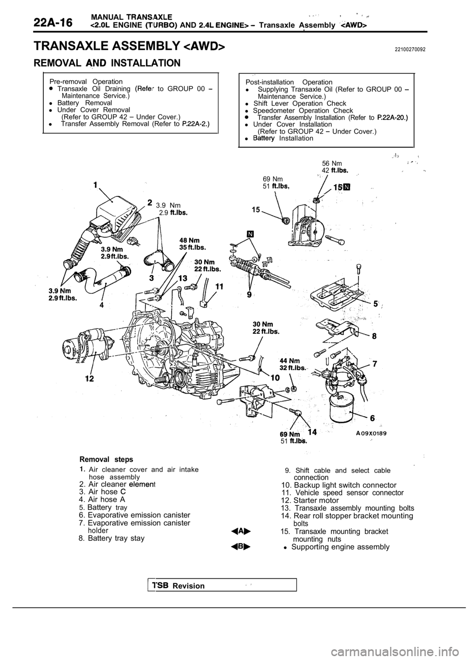
REMOVAL INSTALLATION
22100270092
Pre-removal Operation
Transaxle Oil Draining to GROUP 00 Maintenance Service.)l Battery Removal
l Under Cover Removal
(Refer to GROUP 42
Under Cover.)
l Transfer Assembly Removal (Refer to
3.9 Nm
4
2.9
Post-installation Operation
l Supplying Transaxle Oil (Refer to GROUP 00
Maintenance Service.)l Shift Lever Operation Check
l Speedometer Operation Check
Transfer Assembly Installation (Refer to l Under Cover Installation
(Refer to GROUP 42 Under Cover.)
l Installation
69 Nm
51
56 Nm
42
15
51
Removal steps
Air cleaner cover and air intake
hose assembly
2. Air cleaner
3. Air hose 4. Air hose A
5. Battery tray
6. Evaporative emission canister
7. Evaporative emission canister
holder8. Battery tray stay 9. Shift cable and select cable
connection10. Backup light switch connector11. Vehicle speed sensor connector12. Starter motor13. Transaxle assembly mounting bolts14. Rear roll stopper bracket mountingbolts
15. Transaxle mounting bracket
mounting nuts
l Supporting engine assembly
Revision
Page 877 of 2103

MANUAL TRANSAXLE
ENGINE (TURBO) AND ENGINE> Transaxle Assembly
11
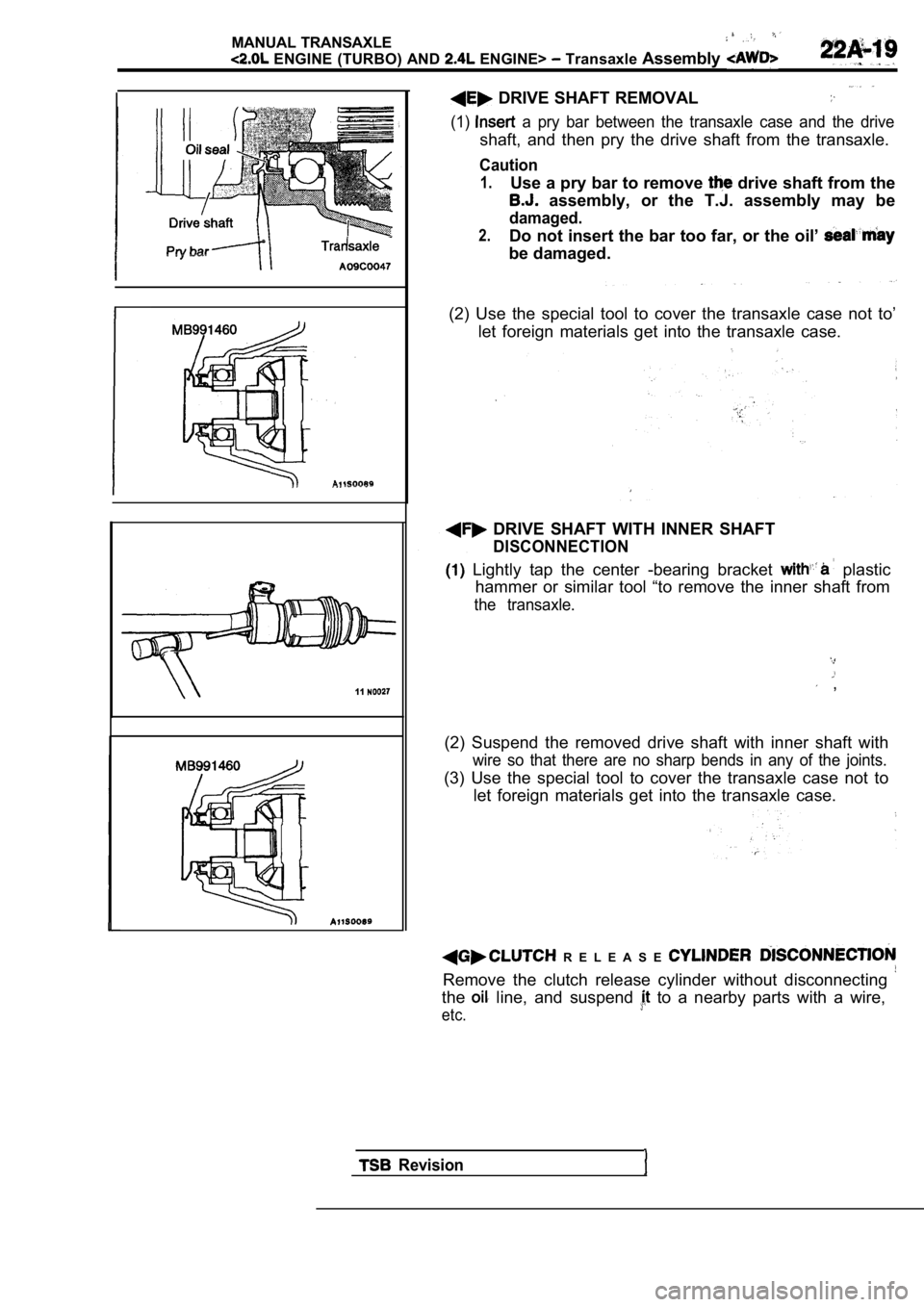
DRIVE SHAFT REMOVAL
(1) a pry bar between the transaxle case and the drive
shaft, and then pry the drive shaft from the transa xle.
Caution
1.Use a pry bar to remove drive shaft from the
assembly, or the T.J. assembly may be
damaged.
2.Do not insert the bar too far, or the oil’
be damaged.
(2) Use the special tool to cover the transaxle cas e not to’
let foreign materials get into the transaxle case.
DRIVE SHAFT WITH INNER SHAFT
DISCONNECTION
Lightly tap the center -bearing bracket plastic
hammer or similar tool “to remove the inner shaft f rom
the transaxle.
,
(2) Suspend the removed drive shaft with inner shaf t with
wire so that there are no sharp bends in any of the joints.
(3) Use the special tool to cover the transaxle case not to
let foreign materials get into the transaxle case.
R E L E A S E
Remove the clutch release cylinder without disconne cting
the line, and suspend to a nearby parts with a wire,
etc.
Revision
Page 886 of 2103
MANUAL TRANSAXLE
ENGINE (NON-TURBO)> Transaxle Control
TRANSAXLE ASSEMBLY
REMOVAL AND INSTALLATION
l Transaxle Oil Draining (Refer to GROUP 00
(Refer to GROUP 42 Under Cover.)
Post-installation Operationl
Supplying Transaxle Oil (Refer to GROUP 00 Maintenance Service.)l Shift Lever Check
l Speedometer ‘Operation Check
l Under Cover Installation
(Refer to GROUP 42
Under Cover.) I n s t a l l a t i o n
8
54Nm
Removal steps
1. Air cleaner cover and air intakehose assembly2. Air cleaner element
3. Battery tray
4. Battery tray stay
5. Shift cable and select cable
connection6. Backup light connectorl b
7. Vehicle speed sensor connector
8. Starter motor
9.
roll stopper bracket mounting
10. Transaxle mounting bracket
mounting nuts
l Supporting engine assembly
Revision
Page 902 of 2103
MANUAL TRANSAXLE OVERHAUL
Items
Transaxle
Backup light switch
Bearing retainer bolt
Bell housing cover mounting bolt
Center differential lock actuator mou
Center differential lock indicator
Center differential shift lever
Differential drive gear bolt
Input shaft lock nut
Interlock plate bolt
Intermediate gear lock nut
3324
33
24
Output gear mounting bolt
Poppet plug
Rear cover bolt
Rear cover bolt
Restrict ball
Reverse brake cone machine screw
Reverse idler gear shaft bolt
Reverse shift lever assembly
Select lever mounting bolt
Shift cable bracket mounting bolt
Speedometer sleeve bolt
Starter motor mounting bolt
Stopper bracket bolt
Transaxle case tightening bolt
Transaxle mount bracket mounting
Transaxle mounting bolt mm
Transaxle mounting bolt mm diamet
Transaxle mounting bolt
mm diamet
Transaxle switch
Revision