Page 1031 of 2103
AUTOMATIC TRANSAXLE ENGINE
(TURBO) AND
ENGINE>
[Comment]l Malfunction of stop light switch
If the stop light switch is ON far 15 minutes or mo re while driving at 3 km/h (2 more, l of connectorthere is a short circuit in the stop light switch a nd diagnostic trouble code No. 28 is output.
l of
SCAN TOOL DTCYes
Is TCL diagnostic trouble code No. 23 Stop light switch check (Refer toGROUP Brake Pedal.)
No NG
Repairl
OK
NG Repair
and stoplight switch.
OK
Check trouble
NG
Replace the TCM.
Page 1056 of 2103
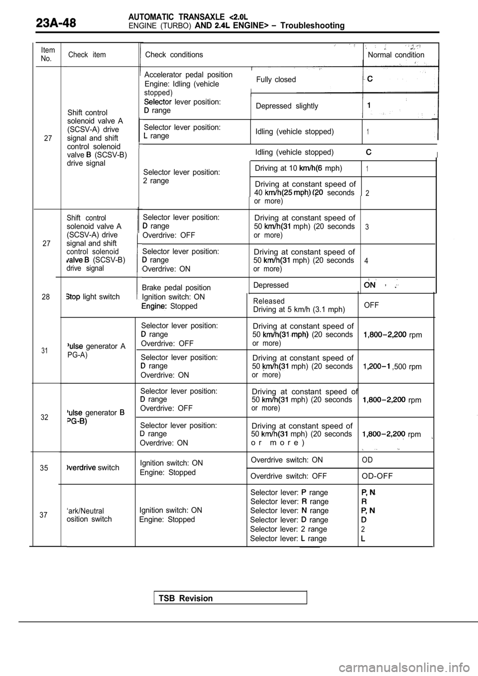
AUTOMATIC TRANSAXLE
ENGINE (TURBO) AND ENGINE> Troubleshooting
Item
No.
27
27
28
31
32
35
37 Check item
Shift control
solenoid valve A
(SCSV-A) drive
signal and shift
control solenoid
valve
(SCSV-B)
drive signal
Shift control
solenoid valve A
(SCSV-A) drive
signal and shift
control solenoid
(SCSV-B)
drive signal
Ignition switch: ON
Stopped
Selector lever position:
range
Overdrive: OFF
Selector lever position:
range
Overdrive: ON
Brake pedal position
light switch
Check conditionsNormal condition
Fully closed
Accelerator pedal position
Engine: Idling (vehicle
stopped)
lever position:
range Depressed slightly
Selector lever position:
range Idling (vehicle stopped)1
Idling (vehicle stopped)I
Selector lever position:
2 range Driving at 10 mph)1
Driving at constant speed of
40 seconds2or more)
Released
Driving at 5 km/h (3.1 mph)
Driving at constant speed of
50 mph) (20 seconds3
or more)
Driving at constant speed of
50 mph) (20 seconds4
or more)
Depressed ,
OFF
Selector lever position:
Driving at constant speed of
range 50 (20 seconds rpm
generator AOverdrive: OFFor more)
PG-A)
Selector lever position:Driving at constant speed of range 50 mph) (20 seconds ,500 rpm
Overdrive: ON
or more)
Selector lever position:Driving at constant speed of range 50 mph) (20 seconds rpm
generator Overdrive: OFFor more)
Selector lever position:Driving at constant speed of range50 mph) (20 seconds rpm
Overdrive: ONo r m o r e )
Ignition switch: ON Overdrive switch: ONOD switchEngine: Stopped
Overdrive switch: OFFOD-OFF
Selector lever: range
Selector lever: range
‘ark/NeutralIgnition switch: ON Selector lever: range
osition switchEngine: Stopped Selector lever: range
Selector lever: 2 range2
Selector lever: range
TSB Revision
Page 1057 of 2103
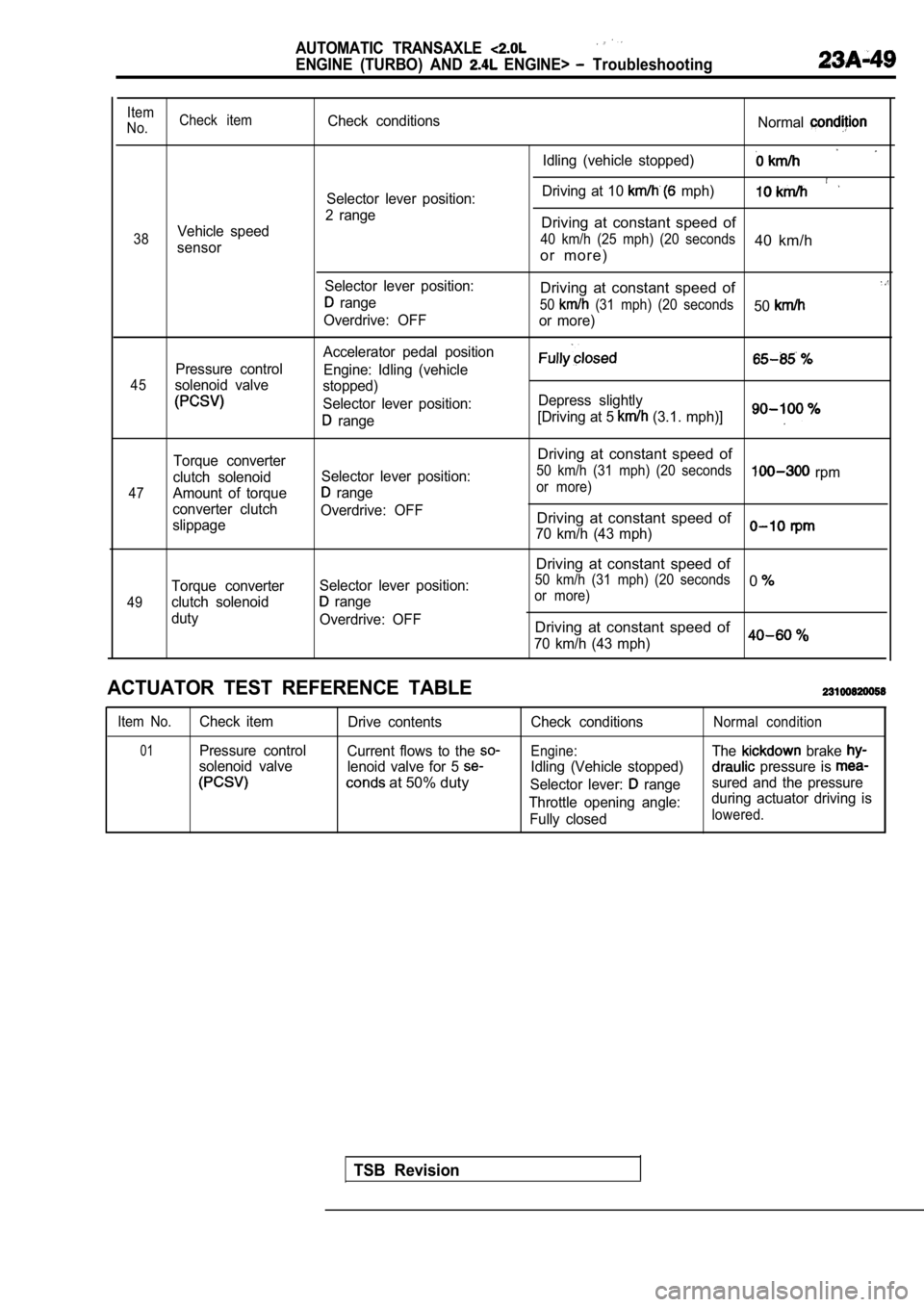
AUTOMATIC TRANSAXLE
ENGINE (TURBO) AND ENGINE> Troubleshooting
Item
No. Check itemCheck conditions
Normal
Idling (vehicle stopped)
Driving at 10 mph)Selector lever position:
2 range
Vehicle speedDriving at constant speed of
38 40 km/h (25 mph) (20 seconds40 km/hsensoro r m o r e )
Selector lever position:Driving at constant speed of range50 (31 mph) (20 seconds50Overdrive: OFF
or more)
Accelerator pedal position
Pressure control Engine: Idling (vehicle
45solenoid valvestopped)
Selector lever position: Depress slightly
range[Driving at 5 (3.1. mph)]
47
49
Torque converter
clutch solenoid
Amount of torque
converter clutch
slippage
Torque converter
clutch solenoid
duty Selector lever position:
range
Overdrive: OFF
Selector lever position:
range
Overdrive: OFF
Driving at constant speed of
50 km/h (31 mph) (20 seconds rpmor more)
Driving at constant speed of
70 km/h (43 mph)
Driving at constant speed of
50 km/h (31 mph) (20 seconds0or more)
Driving at constant speed of
70 km/h (43 mph)0
ACTUATOR TEST REFERENCE TABLE
Item No.Check item Drive contents
01Pressure controlCurrent flows to the
solenoid valve lenoid valve for 5
at 50% duty
Check conditions
Engine:
Idling (Vehicle stopped)
Selector lever:
range
Throttle opening angle: Fully closed
Normal condition
The brake
pressure is
sured and the pressure
during actuator driving is
lowered.
TSB Revision
Page 1059 of 2103
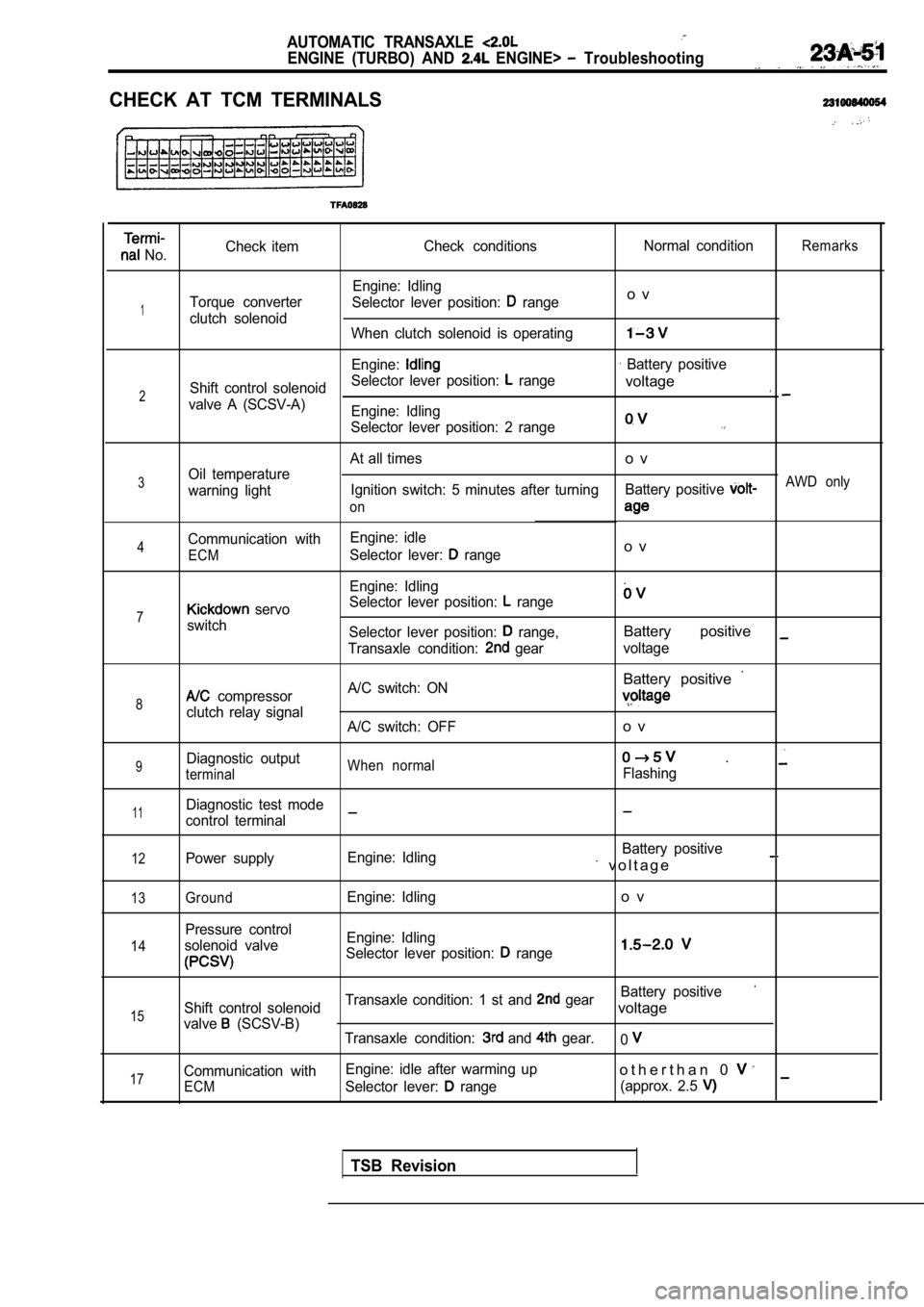
AUTOMATIC TRANSAXLE
ENGINE (TURBO) AND ENGINE> Troubleshooting
CHECK AT TCM TERMINALS
No.Check item
Check conditions Normal conditionRemarks
Engine: Idling
Torque converter Selector lever position:
rangeo v
1clutch solenoid
When clutch solenoid is operating
Engine: Battery positive
Shift control solenoid Selector lever position:
range
2voltage
valve A (SCSV-A)
Engine: Idling
Selector lever position: 2 range
At all timeso v
3Oil temperature
warning light Ignition switch: 5 minutes after turning
Battery positive AWD only
on
Communication with Engine: idle4Selector lever: rangeo vECM
Engine: Idling
Selector lever position:
range7 servo
switch Selector lever position:
range,Battery positive
Transaxle condition: gearvoltage
Battery positive
8 compressor A/C switch: ON
clutch relay signal
A/C switch: OFFo v
9Diagnostic outputWhen normal .
terminalFlashing
11Diagnostic test mode
control terminal
12Power supply Engine: Idling Battery positive v o l t a g e
13
14
15
17
GroundEngine: Idlingo v
Pressure control
solenoid valve Engine: Idling
Selector lever position:
range
Battery positive
Shift control solenoid Transaxle condition: 1 st and gearvoltage
valve (SCSV-B)
Transaxle condition: and gear.0
Communication with Engine: idle after warming upo t h e r t h a n 0
ECMSelector lever: range
(approx. 2.5
TSB Revision
Page 1060 of 2103
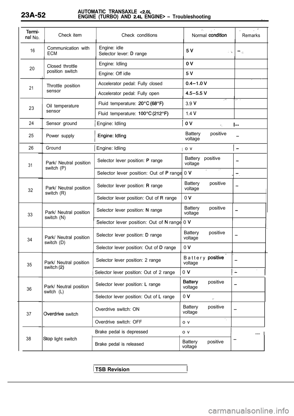
AUTOMATIC TRANSAXLE
ENGINE (TURBO) AND ENGINE> Troubleshooting
No.Check item
Check conditionsNormalRemarks
16Communication withEngine: idle
ECMSelector lever: range
20Closed throttle
position switch Engine: Idling
Engine: Off idle
21
23
24
25
26
31
32
33
34
35
36
37
38
Throttle position
sensor Accelerator pedal: Fully closed
Accelerator pedal: Fully open
Oil temperature
sensor Fluid temperature:
Fluid temperature:
3.9
1.4
Sensor ground Engine: IdlingI--
Power supplyBattery positive
voltage
Ground Engine: IdlingIo v
Park/ Neutral position
Selector lever position: rangeBattery positive
switch (P) voltage
Selector lever position: Out of range 0
Park/ Neutral position
Selector lever position: rangeBattery positive
switch (R) voltage
Selector lever position: Out of
range0
Park/ Neutral position Selector lever position: rangeBattery positive
switch (N) voltageSelector lever position: Out of range 0
Park/ Neutral position
Selector lever position: rangeBattery positive
switch (D) voltage
Selector lever position: Out of
range0
Park/ Neutral position Selector lever position: 2 rangeB a t t e r y
switchvoltage
Selector lever position: Out of 2 range 0
Park/ Neutral position
Selector lever position: range positive
switch (L)voltage
Selector lever position: Out of
range0
switch Overdrive switch: ON
Overdrive switch: OFF
Battery positive
voltage
o v
Brake pedal is depressedo v--- I
light switch Brake pedal is releasedBattery positive voltage
TSB Revision
Page 1065 of 2103
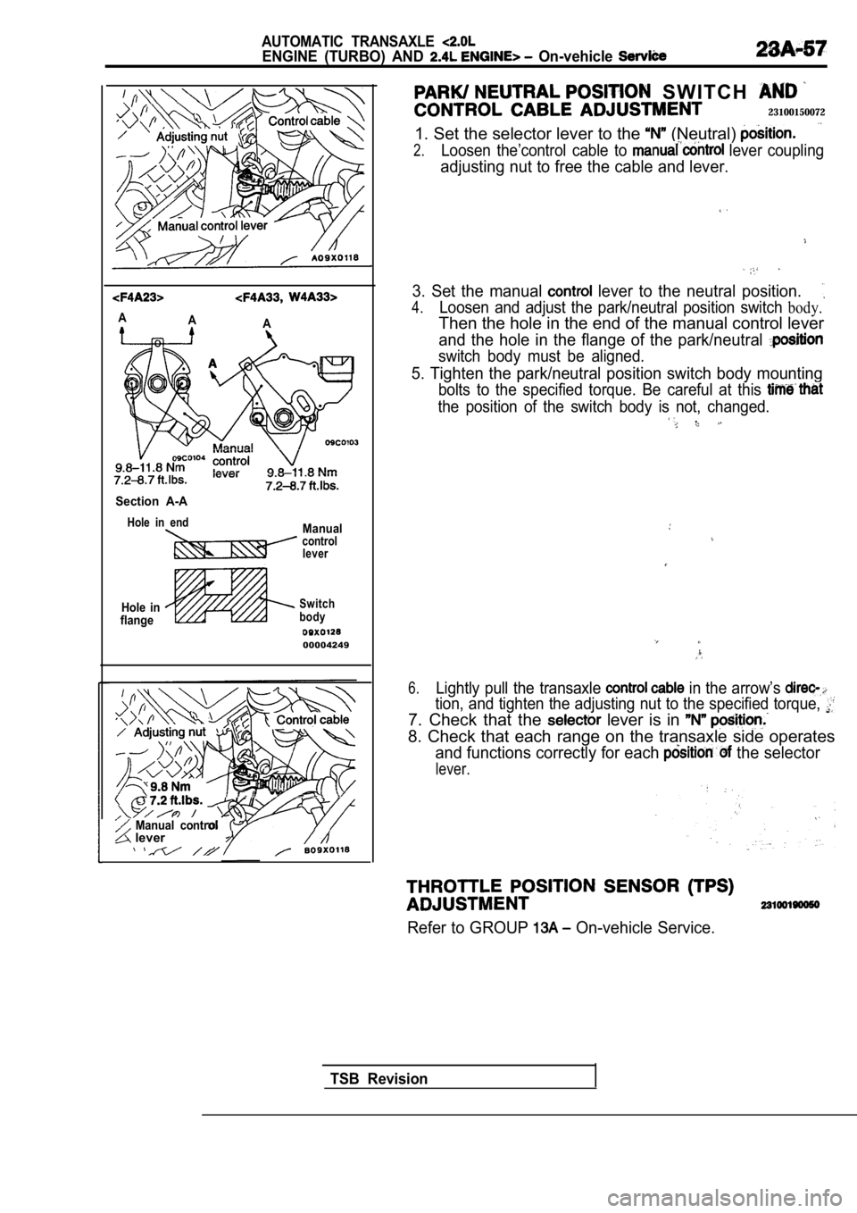
AUTOMATIC TRANSAXLE
ENGINE (TURBO) AND On-vehicle
AA
A
Section A-A
Hole in endManualcontrol
lever
Hole in
flangeSwitch
body
00004249
Manual control lever
S W I T C H
23100150072
1. Set the selector lever to the (Neutral)
2.Loosen the’control cable to lever coupling
adjusting nut to free the cable and lever.
3. Set the manual lever to the neutral position.
4.Loosen and adjust the park/neutral position switch body.
Then the hole in the end of the manual control leve r
and the hole in the flange of the park/neutral
switch body must be aligned.
5. Tighten the park/neutral position switch body mo unting
bolts to the specified torque. Be careful at this
the position of the switch body is not, changed. ,
6.Lightly pull the transaxle in the arrow’s
tion, and tighten the adjusting nut to the specified torque,
7. Check that the lever is in
8. Check that each range on the transaxle side oper ates
and functions correctly for each the selector
lever.
Refer to GROUP On-vehicle Service.
TSB Revision
Page 1101 of 2103
AUTOMATIC TRANSAXLE
ENGINE (TURBO) AND ENGINE>
REMOVAL AND INSTALLATION
Be not subject the any shocks
trol cable and shift lever assembly.
Engine>
8.8 Nm6.5
11 Nm
11 Nm8.3
118.3l
N m . .
NOTE Resin clip position11 Nm
8.3
Transaxle control cable assemblyremoval steps
1. Air cleaner and air intake hose sembly
2. Center panel
3. Cup holder assembly
4. Floor console assembly 5. Console side cover (L.H.)
6. Console side cover
(R.H.)
7. TCM bracket
8. Transaxle control module (TCM)
9. Nut10. Clip 11. Clip
12. Transaxle control cable connection
13. Nut14. Transaxle control cable assembly Selector lever assembly removal
steps
2. Center panel
3. Cup holder assembly
4. Floor console assembly 5. Console side cover (L.H.)
6. Console side cover (R.H.)
11. Clip
12. Transaxle control cable connection
15. Snap pin
16. Key interlock cable connection
17.
lock cable connection
18. Overdrive switch/position indicator
light connector19. Selector lever assembly
TSB Revision
Page 1103 of 2103
AUTOMATIC TRANSAXLE
ENGINE (TURBO) AND
SELECTOR LEVER ASSEMBLY
DISASSEMBLY AND REASSEMBLY
arrow-located places)
Disassembly steps
11 Nm8.3
1. Overdrive switch position indicator12. Position indicator light assembly
light connector case
2.Cover
3. Selector knob4. Overdrive switch button5. Overdrive switch6.Pin
13.Sleeve
14.Bolt15.Lever assembly
16. Detent spring assembly17.Bushing18.Pipe19.Cotter pin20.Washer21.Lock cam22.Bracket assembly
91.5
2Nm
7. Push button8. Spring9. Indicator panel upper10. Slider11. Indicator panel lower
Terminal
Flat-tip screw driver
TSB Revision
DISASSEMBLY SERVICE POINTS
OVERDRIVE SWITCH POSITION INDICATOR
LIGHT CONNECTOR CASE REMOVAL
Use a flat-tip screwdriver or similar tool to pull out the terminal
from the overdrive switch/position indicator light connector
case.