Page 1647 of 2103

BASIC BRAKE SYSTEM
CLEARANCEB E T W E E N B R A K E A N D
REWALL
(1) Turn up thecarpet,etc. under the brake pedal,
(2) Start the engine, depress the brake pedal
with
490 (110 of force.
Standard value 90 mm (3.5 in.)
(3)If the clearance is less than the standard value, c
heck
for air trapped in the brake line,
the lining and the drum, and dragging in the parkin g
brake.
Adjust and replace defective parts as required.
(4) Turn back the carpet,
, .
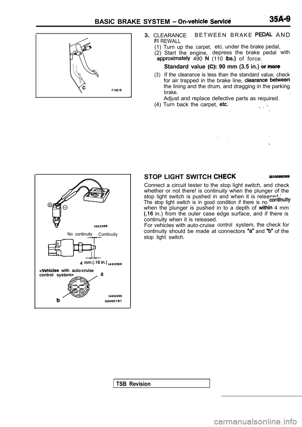
No continuity Continuity
4
with auto-cruise
control systema
STOP LIGHT SWITCH
Connect a circuit tester to the stop light switch, and check
whether or not there! is continuity when the plunge r of the
stop light switch is pushed in and when it is relea sed.’
The stop light switch is in good condition if there is no
when the plunger is pushed in to a depth of 4 mm
in.) from the outer case edge surface, and if ther e is
continuity when it is released. For vehicles with auto-cruise
controlsystem, the check for
continuity should be made at connectors
and of the
stop light switch.
TSB Revision
Page 1648 of 2103

BASIC BRAKE SYSTEM On-vehicle Service
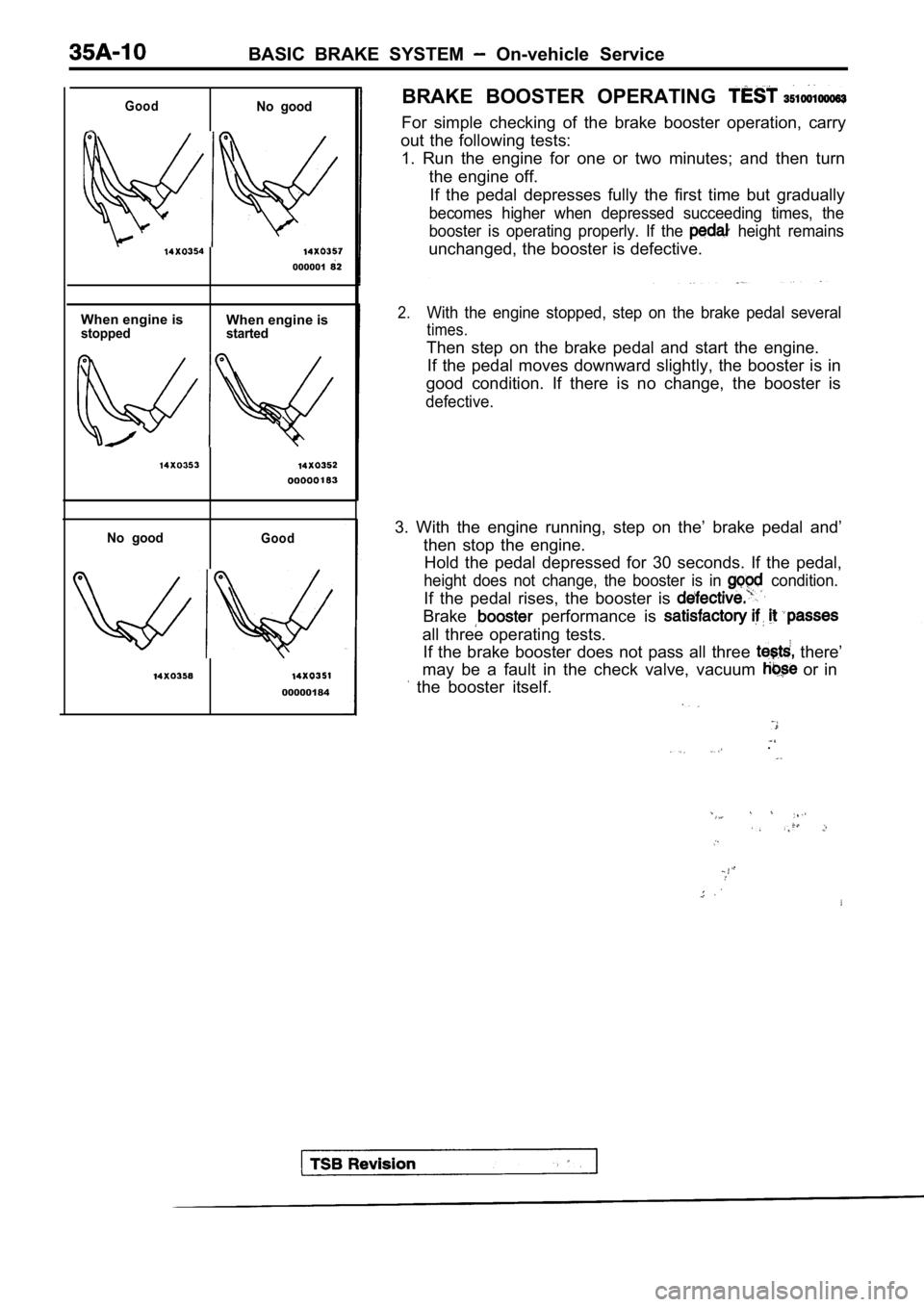
GoodNo good
000001
When engine isWhen engine isstopped started
No goodGood
00000184BRAKE BOOSTER OPERATING
For simple checking of the brake booster operation,
carry
out the following tests: 1. Run the engine for one or two minutes; and then turn
the engine off. If the pedal depresses fully the first time but gra dually
becomes higher when depressed succeeding times, the
booster is operating properly. If the
height remains
unchanged, the booster is defective.
2.With the engine stopped, step on the brake pedal se veral
times.
Then step on the brake pedal and start the engine.
If the pedal moves downward slightly, the booster i s in
good condition. If there is no change, the booster is
defective.
3. With the engine running, step on the’ brake peda l and’
then stop the engine. Hold the pedal depressed for 30 seconds. If the ped al,
height does not change, the booster is in condition.
If the pedal rises, the booster is
Brake performance is
all three operating tests.
If the brake booster does not pass all three
there’
may be a fault in the check valve, vacuum
or in
the booster itself.
.
Page 1662 of 2103
BASIC BRAKE SYSTEM , ,
BRAKE PEDAL
REMOVAL AND INSTALLATION
Post-installation OperationlBrake Pedal Adjustment (Refer to
3022
7
10
‘6
3
2
4
Removal steps
1. Brake return spring
pin
5. Shift lock cable connection
Brake pedal assembly
7. Cotter pin
8. Link assembly
35100340103
30 Nm22
TSB Revision
8
9. Brake pedal shaft bolt10.Bushing
11.Spacer12.Brake pedal
13.Pedal pad
14. Stop light switch
15. Pedal support member assembly
6
Page 1690 of 2103
ABS General Information
The ABS consists of wheel speed sensors, stop light switch, hydraulic unit and the ABS-ECU. If
a problem occurs in the system, the malfunctioning
system can be identified by means of the diagnostic
function.
The diagnostic trouble code will not be erased even
if the ignition switch is turned to OFF.
In addition, reading of diagnostic trouble codes,
service testing are possible using
t h e s c a n
Items
Wheel speed sensor
Front ABS rotor teeth
Rear ABS rotor teeth
,
Magnet coil type
4 3
43
DIAGRAM
1. ABS-ECU6. ABS rotor7. Data link connector .
6. Stop
9. ABS warning light
2. Hydraulic unit
3. ABS valve relay
4. ABS motor relay
5. Wheel speed sensor
TSB Revision
Page 1693 of 2103
warning light
(1) Use the special tool code check
harness) to ground the terminal (1) of the data lin k
connector.
,
.
(2) a ‘reading the trouble code from the
flashing of the ABS warning
.
Diagnostic trouble code No. 24 is output
0.5 sec. No diagnostic trouble code is output 0.5
s e c .
IlluminatedIlluminated
Switched off
.
PauseTens digit DigitFirst digit
time: division: 3
2
NOTE
Diagnostic trouble code No. 16 can be output when t he
ABS system fails because of a battery surge.
Page 1694 of 2103
ABS
ERASING DIAGNOSTIC TROUBLE CODES
With the Scan . .
Connect the scan tool to the data link connector then erase the
With the Warning Light
When the ignition switch is turned on while the sto p light switch is on,
10 times in succession according to the timing given below.
C a u t i o n
The memory cannot be erased under the following con ditions.
(1) When the stop light switch is not turned on and off according to the
(2) When the generator terminal voltage increased (HI state).
Ignition switch
Generator
terminal voltage
Stop light switch
Warning light
ON
OFF
II
ON
OFF_ _
ABS-ECU memory . . .Eliminated
TSB Revision
Page 1695 of 2103

ABS Troubleshooting
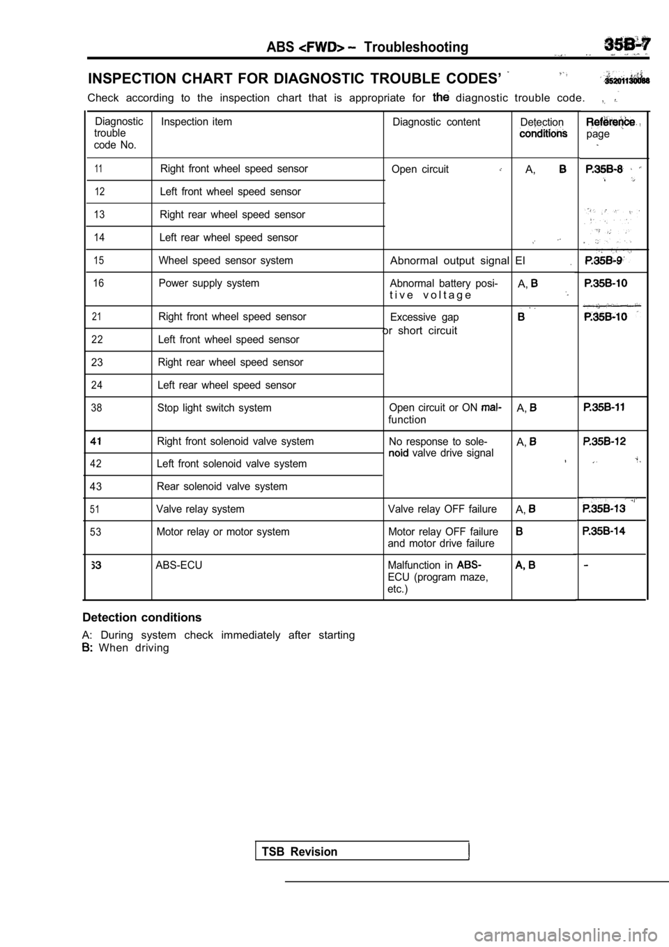
INSPECTION CHART FOR DIAGNOSTIC TROUBLE CODES’
Check according to the inspection chart that is appropriate for diagnostic trouble code.
Diagnostic
Inspection item Diagnostic contentDetection
trouble
code No.
11Right front wheel speed sensor
12Left front wheel speed sensor
13Right rear wheel speed sensor
14Left rear wheel speed sensor
15Wheel speed sensor system
16Power supply system
21Right front wheel speed sensor
22Left front wheel speed sensor
23 Right rear wheel speed sensor
24Left rear wheel speed sensor
38Stop light switch system
Right front solenoid valve system
42Left front solenoid valve system
43 Rear solenoid valve system
51Valve relay system
53Motor relay or motor system Open circuit
A,
Abnormal output signal El.
Abnormal battery posi-A,t i v e v o l t a g e
Excessive gap
or short circuit
Open circuit or ON A,
function
No response to sole-
A, valve drive signal
Valve relay OFF failureA,
Motor relay OFF failure
and motor drive failure
ABS-ECU Malfunction in
ECU (program maze,
etc.)
Detection conditions
A: During system check immediately after starting
When driving
TSB Revision
page
Page 1699 of 2103
ABS
Code No. 38 Stop light switch system
[Comment]
The ABS-ECU outputs this diagnostic trouble code in the following cases.l Malfunction of stop light switch Malfunction of or lStop light switch remains on for more than 15 minutes while the ABS is . M a l f u n c t i o n ing.l The harness wire for the stop light switch may be o pen-circuited.If the stop light operates normally, there is an open circuit in the harness for the
stop light switch input circuit or there is a malfu nction in the ABS-ECU.
Yes
Stop light switch check (Refer to
GROUP On-vehicle Service.) Replace the
Measure at ABS-ECU connector l
Disconnect the connector and mea-
sure at the harness side.
l Stop light switch: ON
lVoltage between terminal 29 and body
ground
OK Battery positive
OK
Check the following connector:
l
OK
Check trouble symptom.
NG Repair
NG Replace the ABS-ECU.
Revision