1990 MITSUBISHI SPYDER light
[x] Cancel search: lightPage 1753 of 2103
Caution,
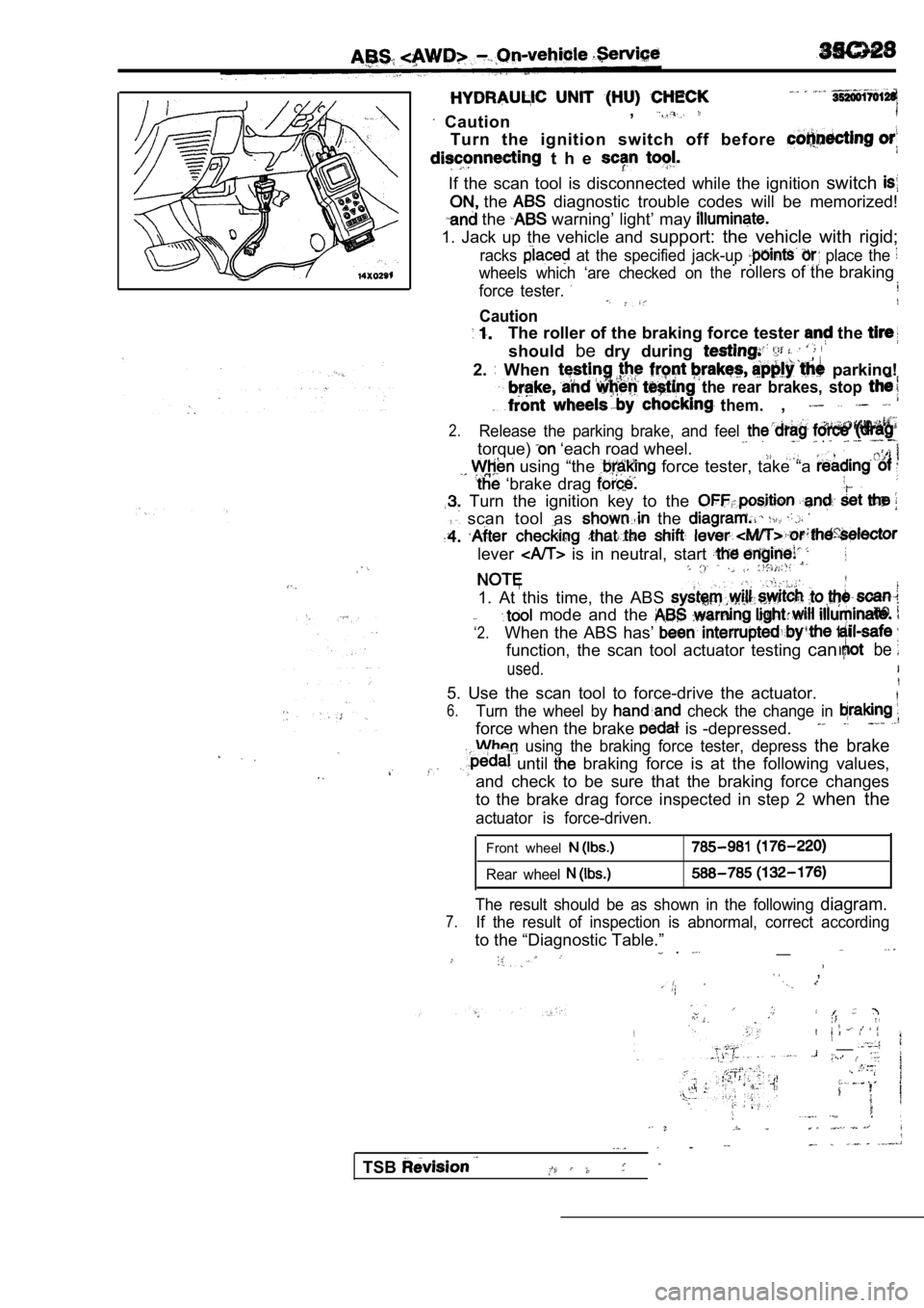
Turn the ignition switch off before
t h e
If the scan tool is disconnected while the ignition
switch
the diagnostic trouble codes will be memorized!
the warning’ light’ may
1. Jack up the vehicle and support: the vehicle with rigid;
racks at the specified jack-up place the
wheels which ‘are checked on. .therollers of the braking
force tester.
Caution
The roller of the braking force tester the
shouldbedry during
2. When parking!
the rear brakes, stop
them.,
2.Release the parking brake, and feel
torque) ‘each road wheel. .
using “the force tester, take “a
‘brake drag
Turn the ignition key to the
scan tool as the
lever is in neutral, start
1. At this time, the ABS
‘2.
mode and the
When the ABS has’
function, the scan tool actuator testing canbe
used.
5. Use the scan tool to force-drive the actuator.
6.Turn the wheel by check the change in
force when the brake is -depressed.
using the braking force tester, depress the brake
until braking force is at the following values,
and check to be sure that the braking force changes
to the brake drag force inspected in step 2 when the
actuator is force-driven.
Front wheel
Rear wheel
The result should be as shown in the following diagram.
7.If the result of inspection is abnormal, correct ac cording
to the “Diagnostic Table.”__ .
,
__
TSB
Page 1756 of 2103
ABS On-vehicle Service
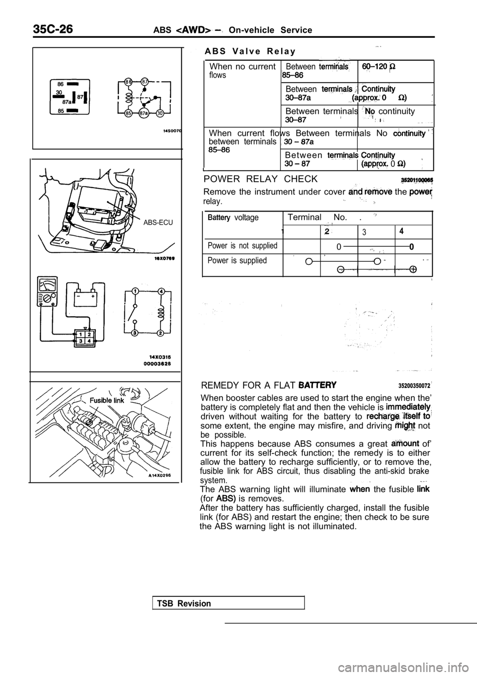
ABS-ECU
14
32
A B S V a l v e R e l a y
When no current
flows
Between
Between
Between terminals continuity
When current flows Between terminals No
between terminals
B e t w e e n
0
POWER RELAY CHECK
Remove the instrument under cover the
relay.
voltageTerminal No. .
34
Power is not supplied00
Power is supplied.
REMEDY FOR A FLAT ,35200350072
When booster cables are used to start the engine wh en the’
battery is completely flat and then the vehicle is
driven without waiting for the battery to
some extent, the engine may misfire, and driving not
be possible.
This happens because ABS consumes a great of’
current for its self-check function; the remedy is to either
allow the battery to recharge sufficiently, or to r emove the,
fusible link for ABS circuit, thus disabling the an ti-skid brake
system.
The ABS warning light will illuminate the fusible
(for is removes.
After the battery has sufficiently charged, install the fusible
link (for ABS) and restart the engine; then check t o be sure
the ABS warning light is not illuminated.
TSB Revision
Page 1763 of 2103
CONTENTS
GENERAL INFORMATION. . . . . . . . . . . . . . . . . . 2PARKING BRAKE LEVER*. . . . . . . . . . . . . . . . . . 6
LUBRICANTS. . . . . . . . . . . . . . . . . . . . . . . . . . . . . . .3ON-VEHICLE SERVICE . . . . . . . . . . . . . . . . . . . . . 4
PARKING BRAKE CABLE
. . . . . . . . , . .5
7Parking Brake Lever Stroke
Check and. . . . . . . . . . . . . . . . . . . . . . . . . . . . . . . . . . . . . . . . . . . .Adjustment . . . . . . . , . . . . . . . . . . . . . . . . . . . . . . . . . .
4
PARKING BRAKE CABLE
BRAKE>*. . . . . . . . . . . . . . . . . . . . . . . . . .
. . . . . . . .8‘SERVICE SPECIFICATIONS . . . . . . . . . . . . . . 3
PARKING BRAKE DRUM . . . . . . . . . . . . . . . . . . 10
TROUBLESHOOTING. . . . . . . . . . . . .
3
WARNINGS REGARDING SERVICING OF SUPPLEMENTAL RESTRA INT SYSTEM EQUIPPED VEHICLES
WARNING!
(1)Improperservice or maintenance of any component of the or any component, can lead to inadvertent firingofthealr renderingthe inoperative).(2) Service or maintenance of any component or component must be performed only at an authorized dealer. MITSUBISHI dealer personnel must thoroughly review this manual, and especially its GROUP Supplemental
Restraint System and GROUP 00 Maintenance Service before beginning any service o r of anycomponent of the or any component.
NOTEThe SRS includes the following SRS warning light, air bag module, clock spring and interconnecting wiring. SRS-related components (that may have to be in connection SRS service or maintenance) are
.. . . indicated the ot contents by an asterisk
Page 1775 of 2103
CONTENTS
GENERAL INFORMATION. . . . . . . . . . . . . . . . . . 2POWER STEERING GEAR . . . . . . . . . . 18
LUBRICANTS. . . . . . . . . . . . . . . . . . . . . . . . . . . . . .
3P O W E R S T E E R I N G H O S E ’ S
Engine . . . . .
ON-VEHICLE SERVICE . . . . . . . . . . . . . . . . . . . . . 7 Engine (Turbo) and . . . 47
Bleeding. . . . . . . . . . . . . . . . . . . . . . . . . . . . . . . . . . . .9
Checking Steering Wheel Return to Center
. . . .8
Fluid Level Check. . . . . . . . . . . . . . . . . . . . . . . . . . .8
Fluid Replacement. . . . . . . . . . . . . . . . . . . . . . . . . . .9
Oil Pump Test
. . . . . . . . . . . . . . . . . . . . .
Power Steering Pressure Switch Check
. . . . . . .13
Stationary Steering Effort Check. . . . . . . . . . . . . .8
Steering Angle Check. . . . . . . . . . . . . . . . . . . . . . . .7
Steering Wheel Free Play Check. . . . . . . . . . . . . . .7
Tie Rod End Ball Joint Breakaway Torque Check
. . . . . . . . . . . . . . . . . . . . . . . . . . . . . . . . . . . . . . . . . . . . .
7
POWER STEERING OIL PUMP
Engine (Non-turbo)> . . . . . . . . . . . . . . .
Engine (Turbo) and Engine> . . . 39
SEALANTS. . . . . . . . . . . . . . . . . . . . . . . . . . . . . . . .4
SERVICE SPECIFICATIONS . . . . . . . . . . . . . . . . . 3
SPECIAL TOOLS. . . . . . . . . . . . . . . . . . . . . . . . . . .4
STEERING WHEEL AND
. . . . . . . . . . 14
WARNINGS REGARDING SERVICING OF SUPPLEMENTAL (SRS) EQUIPPED
WARNING!(1)Improper service or maintenance of any component of the SRS, or any SRS-related component, can lead
the SRS inoperative).(2) Service or maintenance of any SRS component or component must be performed MITSUBISHI dealer.(3) MITSUBISHI dealer personnel must this and especially its GROUP straint System (SRS) and GROUP 00 -Maintenance beginning any service or maintenance of any com-
ponent of the SRS or any
NOTEThe includes the following components: SRS light, air bag module, and interconnecting wiring.Other SRS-related components (that may have to be r emoved/installed in with service or maintenance) are indi-
cated in the table of contents by an asterisk
Page 1781 of 2103
STEERING On-vehicle”
TSB Revision
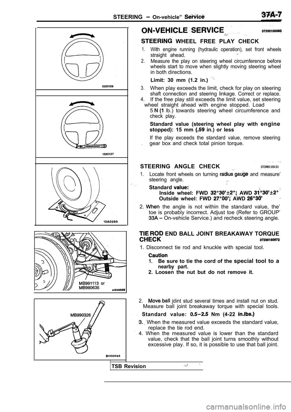
WHEEL FREE PLAY CHECK
1.With engine running (hydraulic operation), set front wheels
straight ahead.
2.Measure the play on steering wheel circumference be fore
wheels start to move when slightly moving steering wheel
in both directions.
Limit: 30 mm (1.2 in.)
3.When play exceeds the limit, check for play on steering
shaft connection and steering linkage. Correct or replace.
4.If the free play still exceeds the limit value, set steering
wheel straight ahead with engine stopped. Load
5
(1 lb.) towards steering wheel circumference and
check play.
Standard value (steering wheel play with engine
stopped): 15 mm
in.) or less
If the play exceeds the standard value, remove stee ring
. .gear box and check total pinion torque.
STEERING ANGLE CHECK
37200110131
1.Locate front wheels on turning and measure’
steering angle.
Standard
Inside wheel: FWD AWD
Outside wheel: FWD AWD
2. the angle is not within the standard value, the’
toe is probably incorrect. Adjust toe (Refer to GRO UP’
On-vehicle Service.) and recheck steering angle.
END BALL JOINT BREAKAWAY TORQUE
1. Disconnect tie rod and knuckle with special tool .
1.Be sure to tie the cord of the special tool to a
nearby part.
2. Loosen the nut but do not remove it.
2. jdint stud several times and install nut on stud.
Measure ball joint breakaway torque with special to ols.
Standard value:
Nm (4-22
When the measured value exceeds the standard value ,
replace the tie rod end.
4. When the measured value is lower than the standa rd
value, check that the ball joint turns smoothly wit hout
excessive play. If so, it is possible to use that b all joint.
Page 1827 of 2103
REMOVAL AND INSTALLATION
0 0 0 0 3 7 9 7Adjustment of clearance around
hood and height
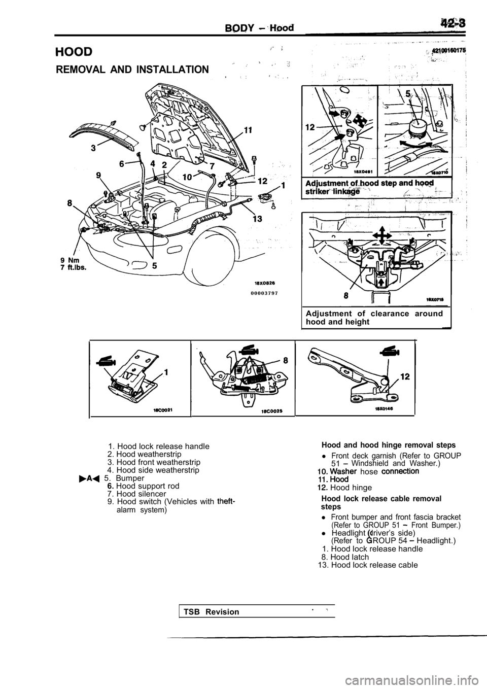
1. Hood lock release handle
2. Hood weatherstrip
3. Hood front weatherstrip
4. Hood side weatherstrip
5. Bumper 6. Hood support rod
7. Hood silencer 9. Hood switch (Vehicles with
alarm system)
Hood and hood hinge removal steps
l Front deck garnish (Refer to GROUP51Windshield and Washer.)
hose
Hood hinge
Hood lock release cable removal
steps
l Front bumper and front fascia bracket(Refer to GROUP 51 Front Bumper.)l Headlight driver’s side)(Refer toROUP 54 Headlight.)
1. Hood lock release handle
8. Hood latch
13. Hood lock release cable
TSB Revision .
Page 1835 of 2103
and Window Glass
installation bolt
up-stop bolt
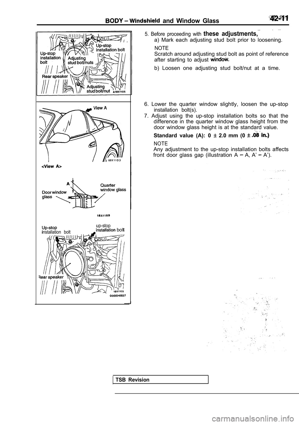
5. Before proceeding with these adjustments,
a) Mark each adjusting stud bolt prior to loosening.
NOTE
Scratch around adjusting stud bolt as point of reference
after starting to adjust
b) Loosen one adjusting stud bolt/nut at a time.
6. Lower the quarter window slightly, loosen the up -stop
installation bolt(s).
7. Adjust using the up-stop installation bolts so that the
difference in the quarter window glass height from the
door window glass height is at the standard value.
Standard value (A): 0 2.0 mm (0
NOTE
Any adjustment to the up-stop installation bolts af fects
front door glass gap (illustration A
A, A’ A’).
TSB Revision
Page 1840 of 2103
BODY Windshield and Window Glass
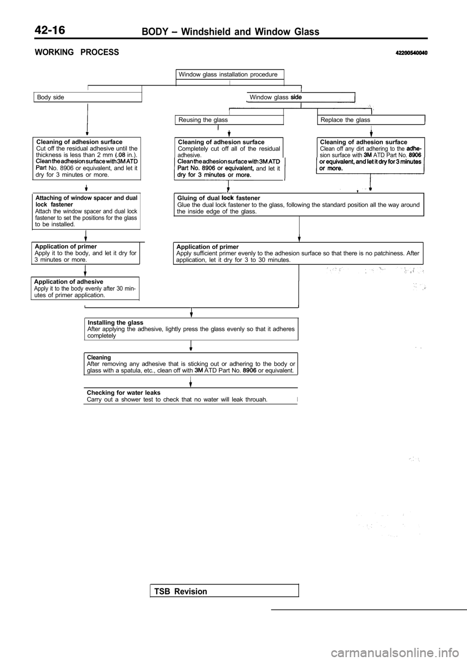
WORKING PROCESS
I
Window glass installation procedure
I
Body sideWindow glass
Cleaning of adhesion surface
Cut off the residual adhesive until the
thickness is less than 2 mm
in.).
No. 8906 or equivalent, and let it
dry for 3 minutes or more.
Attaching of window spacer and dual
lock fastener
Attach the window spacer and dual lock
fastener to set the positions for the glass
to be installed.
Application of primer Application of primer
Apply it to the body, and let it dry for
3 minutes or more. Apply sufficient primer evenly to the adhesion surf
ace so that there is no patchiness. After
application, let it dry for 3 to 30 minutes.
Application of adhesive
Apply it to the body evenly after 30 min-utes of primer application.
IReusing the glassReplace the glass
I
Cleaning of adhesion surface
Completely cut off all of the residual
adhesive.
Cleaning of adhesion surfaceClean off any dirt adhering to the sion surface with ATD Part No. or equivalent, and let it dry for 3 minutesPart No. 8906 or equivalent and let it
Gluing of dual fastenerGlue the dual lock fastener to the glass, following the standard position all the way around
the inside edge of the glass.
Installing the glass
After applying the adhesive, lightly press the glas s evenly so that it adheres
completely
TSB Revision
CleaningAfter removing any adhesive that is sticking out or adhering to the body or
glass with a spatula, etc., clean off with ATD Part No. or equivalent.
I
Checking for water leaks
Carry out a shower test to check that no water will leak throuah.I