Page 1943 of 2103

EXTERIOR Wiper and .
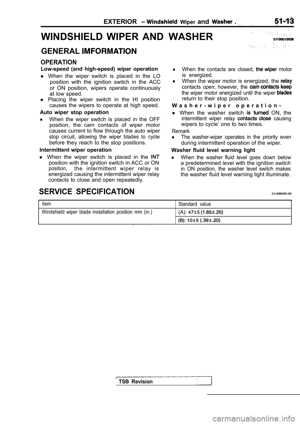
WINDSHIELD WIPER ANDWASHER
GENERAL
OPERATION
Low-speed (and high-speed) wiper operation
l When the wiper switch is placed in the LO
position with the ignition switch in the ACC
or ON position, wipers operate continuously
at low speed.
l Placing the wiper switch in the HI position
causes the wipers to operate at high speed.
Auto wiper stop operation
lWhen the wiper switch is placed in the OFF position, the cam contacts of wiper motor
causes current to flow through the auto wiper
stop circuit, allowing the wiper blades to cycle
before they reach to the stop positions.
Intermittent wiper operation
l When the wiper switch is placed in the
position with the ignition switch in ACC or ON
position,the intermittent wiper relay is
energized causing the intermittent wiper relay
contacts to close and open repeatedly.
lWhen the contacts are closed, motor
is energized.
lWhen the wiper motor is energized, the
contacts open; however, the
the wiper motor energized until the wiper
return to their stop position.
W a s h e r - w i p e r o p e r a t i o n -
l When the washer switch
ON, the
intermittent wiper relay causing
wipers to cycle’ one to two times.
Remark
lThe washer-wiper operates in the priority even
during intermittent operation of the wiper.
Washer fluid level warning light
lWhen the washer fluid level goes down below
a predetermined level with the ignition switch
in ON position, the washer level switch makes
the washer fluid level warning light illuminate.
SERVICE SPECIFICATION51100030140
Item
Windshield wiper blade installation position mm (in .)Standard value(A):
TSB Revision
Page 1959 of 2103

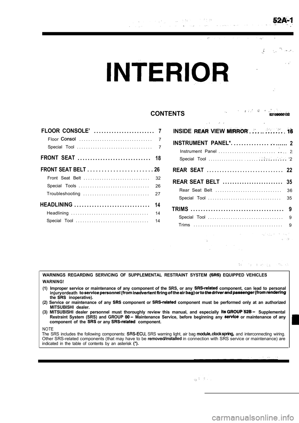
CONTENTS
FLOOR CONSOLE’. . . . . . . . . . . . . . . . . . . . . . . .7INSIDE VIEW .....
Floor. . . . . . . . . . . . . . . . . . . . . . . . . . . . . . . .7INSTRUMENT PANEL*.. . . . . . . . . . . . . .......2Special Tool . . . . . . . . . . . . . . . . . . . . . . . . . . . . . . . . . 7
Instrument Panel . . . . . . . . . . . . . . . . . . . . . . . . .. .2:
FRONT SEAT. . . . . . . . . . . . . . . . . . . . . . . . . . . . .18Special Tool. . . . . . . . . . . . . . . ... . . . .. ‘2
FRONT SEAT BELT . . . . . . . . . . . . . . . . . . . . . . . 26REAR SEAT. . . . . . . . . . . . . . . . . . . . . . . . . . . . . .22
Front Seat Belt
. . . . . . . . . . . . . . . . . . . . . . . . . . . . . 32REAR SEAT BELT. . . . . . . . . . . . . . . . . . . . . . . . .35Special Tools . . . . . . . . . . . . . . . . . . . . . . . . . . . . . . .
26
3 6
Troubleshooting Rear Seat Belt
. . . . . . . . . . . . . . . . . . . . . . . . . . . . .
. . . . . . . . . . . . . . . . . . . . . . . . . . . . . 27
Special Tool . . . . . . . . . . . . . . . . . . . . . . . . . . . . . . . . 35
HEADLINING. . . . . . . . . . . . . . . . . . . . . . . . . . . . . .14TRIMS. . . . . . . . . . . . . . . . . . . . . . . . . . . . . . . . . . . . .9Headlining . . . . . . . . . . . . . . . . . . . . . . . . . . . . . . . . . .14Special Tool. . . . . . . . . . . . . . . . . . . . . . . . . . . . . . . . .9Special Tool . . . . . . . . . . . . . . . . . . . . . . . . . . . . . . . .14Trims. . . . . . . . . . . . . . . . . . . . . . . . . . . . . . . . . . . . . . .
9
WARNINGS REGARDING SERVICING OF SUPPLEMENTAL RESTRA INT SYSTEM EQUIPPED VEHICLES
WARNING!
(1)
Improper service or maintenance of any component of the SRS, or any component, can lead to personal
injuryordeath
the inoperative).
(2) Service or maintenance of any component or component must be performed only at an authorized
MITSUBISHI dealer.
(3) MITSUBISHI dealer personnel must thoroughly rev iew this manual, and especially
Supplemental
Restraint System (SRS) and GROUP Maintenance Service, before beginning any or maintenance of any
component of the or any component.
NOTEThe SRS includes the following components: SRS warning light, air bag and interconnecting wiring.Other SRS-related components (that may have to be in connection with SRS service or maintenance) areindicated in the table of contents by an asterisk
Page 1964 of 2103
INTERIOR
Disassembly steps
1. Glove box under frame
2. Glove box light switch
3. Glove box light bracket
4. Glove box striker
5. Defroster garnish
.
6 . R h e o s t a t
7. Striker
8. Side face garnish 9. w i r i n g h a r n e s s
DISASSEMBLY AND REASSEMBLY
TSB Revision
Page 1965 of 2103
INTERIOR Floor Console
FLOOR CONSOLE
SPECIAL TOOL
ToolTool number and nameSupersession Application
General service tool Removal of panel, holder, etc.
FLOOR CONSOLE
REMOVAL AND INSTALLATION
CAUTION:When removing and installing the floor console as-sembly, do not let it bump against the
NOTE Metal clip position
Removal steps
1. Center console panel
2. Ashtray and cupholder assembly
3. Ashtray
4. Cup holder 5. Shift lever knob
6. Floor console assembly
7. Ashtray illumination light bracket
TSB Revision
Page 1972 of 2103
HEADLINING
INTERIOR Headlining
SPECIAL TOOL
ToolTool number and name
General service toolApplication
Removal of trims, etc.
HEADLINING
REMOVAL AND INSTALLATION
52100140178
and Post-installation Operationl Front Pillar Trim and Quarter Trim Upper Removaland Installation (Refer to
NOTE Metal clip position
Removal steps
a s s e m b l y
2. holder
3. Dome light assembly
4. Rear roof rail trim
5. Headlining
TSB Revision
Rear roof rail trimI
Page 1973 of 2103
INTERIOR Headlining
,
00003744
NOTE Metal clip position
Rear roof rail
Removal steps
1. assembly
2. holder
3. Rear roof rail trim
4. Sunroof inner weatherstrip 5. Sunroof switch cover
6. Sunroof switch panel
7. Headlining
Tab
REMOVAL SERVICE POINT
DOME LIGHT ASSEMBLY REMOVAL
Press and pull the tab downward to remove the dome light
assembly.
INSTALLATION SERVICE POINT
SUNROOF INNER WEATHERSTRIP
INSTALLATION
Install the sunroof inner weatherstrip with its adhered joint
located toward the rear of the vehicle and on its c enter line.
Adhered joint
Front of vehicle
Page 1984 of 2103
INTERIOR Front Seat Belt
FRONT SEAT BELT
GENERAL IMFORMATION
OPERATION
lWhen the ignition switch is turned ON, the deci-
sion circuit operates and the seat belt warning
light inside of the combination meter flashes
four times for 6 seconds.
l
The decision circuit output makes the seat belt
warning buzzer sound intermittently for 6 se-
conds to indicate unfastening of the seat belt.
SPECIAL TOOLS
lWhen the seat belt is buckled (seatbelt switch
is turned ON), the seat belt warning buzzer
stops sounding.
When the ignition switch is turned OFF, both
seat belt warning light and buzzer do not oper-
ate.
TSB Revision
Page 1986 of 2103

INTERIOR Front Seat Belt
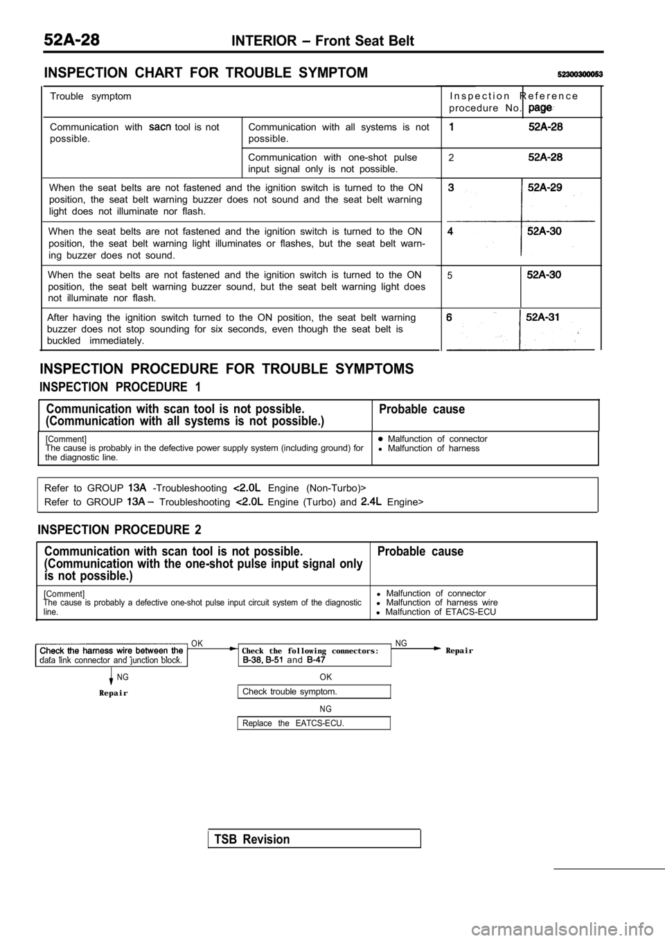
INSPECTION CHART FOR TROUBLE SYMPTOM
Trouble symptom
Communication with
tool is not
possible. Communication with all systems is not
possible.
Communication with one-shot pulse
input signal only is not possible.
When the seat belts are not fastened and the igniti on switch is turned to the ON
position, the seat belt warning buzzer does not sou nd and the seat belt warning
light does not illuminate nor flash.
When the seat belts are not fastened and the igniti on switch is turned to the ON
position, the seat belt warning light illuminates o r flashes, but the seat belt warn-
ing buzzer does not sound.
When the seat belts are not fastened and the igniti on switch is turned to the ON
position, the seat belt warning buzzer sound, but t he seat belt warning light does
not illuminate nor flash.
After having the ignition switch turned to the ON p osition, the seat belt warning
buzzer does not stop sounding for six seconds, even though the seat belt is
buckled immediately.
INSPECTION PROCEDURE FOR TROUBLE SYMPTOMS
INSPECTION PROCEDURE 1
I n s p e c t i o n R e f e r e n c e
p r o c e d u r e N o .
2
3
4
5
Communication with scan tool is not possible.
(Communication with all systems is not possible.) Probable cause
[Comment] Malfunction of connector
The cause is probably in the defective power supply system (including ground) for
l Malfunction of harness
the diagnostic line.
Refer to GROUP
-Troubleshooting Engine (Non-Turbo)>
Refer to GROUP
Troubleshooting Engine (Turbo) and Engine>
INSPECTION PROCEDURE 2
Communication with scan tool is not possible. Probab le cause
(Communication with the one-shot pulse input signal only
is not possible.)
[Comment]l Malfunction of connectorThe cause is probably a defective one-shot pulse in put circuit system of the diagnosticl Malfunction of harness wireline.l Malfunction of ETACS-ECU
OK NG Check the following connectors: Repairdata link connector and junction block. and
NGOK
RepairCheck trouble symptom.
N G
Replace the EATCS-ECU.
TSB Revision