Page 1845 of 2103
B O D Y and Window
(4) aligning
and evenly so that” it “adheres completely.
glass), place it somewhere where it will not disturbed,
Caution
If heat is applied with an infra-red light to shorten
the setting time, keep the surface temperature of t he
a d h e s i v e
(6) After attaching the windshield to the body, let it stand
far 30 minutes or more, then test for water leakage.
1. If moving the vehicle: should be done gently.
2.When testing for water do not pinch the
end of the to spray the water.
TSB Revision
Page 1853 of 2103
BODY Windshield. and Window
REMOVAL AND INSTALLATION
Pre-removal and Post-installation Operation
Removal and Installation
l Rear Wiper Arm(Refer to GROUP 51 Rear Wiper and Washer.)l Upper Trim, Lower Trim and Side Trim (Refer to GROUP Trims.)l High-mounted Stop Light without rearspoiler, (Refer to GROUP 54 High-mounted Stop
Light.)
Adhesive tape:
or equivalent
Section C-C24
Section
Section D-D
mm (in.). .
Adhesive:
ATD Part No. Super Fast Urethane and ATD Part No. 8608 Super Fast Urethane prim& equivalent
Removal steps
Harness connector 3. m o l d i n g
2. g l a s s Dual-lock fasteners
TSB Revision
Page 1890 of 2103

B O D Y
REMOVAL AND INSTALLATION
7
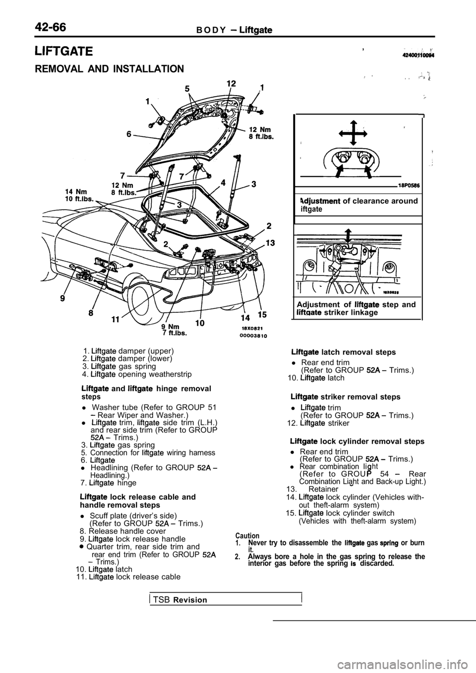
1. damper (upper)
2. damper (lower)
3. gas spring
4. opening weatherstrip
and hinge removal
steps
l Washer tube (Refer to GROUP 51 Rear Wiper and Washer.)
l trim, side trim (L.H.)
and rear side trim (Refer to GROUP
Trims.)
3. gas spring5. Connection for wiring harness6.l Headlining (Refer to GROUP Headlining.)7. hinge
lock release cable and
handle removal steps
l Scuff plate (driver’s side)
(Refer to GROUP
Trims.)
8. Release handle cover
9.
lock release handle Quarter trim, rear side trim andrear end trim (Refer to GROUP Trims.)10. latch
11. lock release cable ,
, ,
of clearance around
iftgate
Adjustment of step and striker linkage
latch removal steps
l Rear end trim
(Refer to GROUP
Trims.)
10. latch
striker removal steps
l
trim
(Refer to GROUP Trims.)
12. striker
lock cylinder removal steps
l Rear end trim
(Refer to GROUP
Trims.)l Rear combination Iiht( R e f e r t o G R O U54 RearCombination Liaht and Back-up Light.)13. Retainer
14. lock cylinder (Vehicles with-out theft-alarm system)
15. lock cylinder switch(Vehicles with theft-alarm system)
Caution1.Never try to disassemble the gas or burnit.2.Always bore a hole in the gas spring to release the interior gas before the spring discarded.
TSB Revision
Page 1891 of 2103
BODY __.
LUBRICANT POINTS
0 0 0 0 3 8 1 1
INSPECTION
LUGGAGE COMPARTMENT LIGHT SWITCH CONTINUITY
CHECK (INCLUDING LATCH)
Switch positionTerminal No.
12 (Ground)
ON (Latch open)
0 0
OFF (Latch shut)
LOCK CYLINDER SWITCH CONTINUITY CHECK
Switch positionTerminal No.
12
LOCK00
Neutral (OFF)
UNLOCK
TSB Revision
Page 1896 of 2103

42-72BODY Entry System
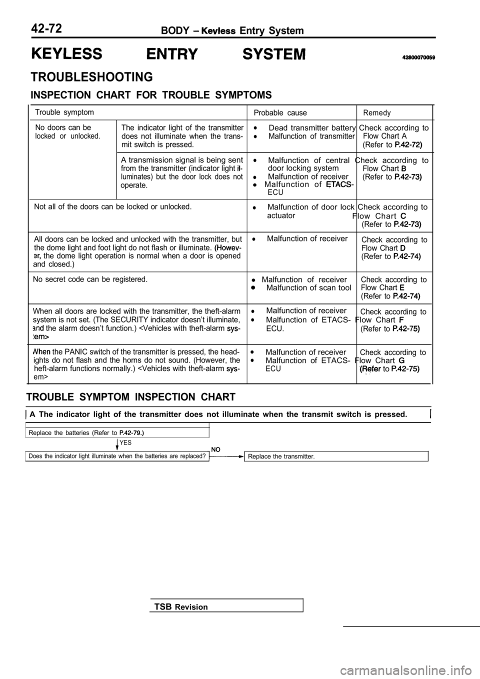
TROUBLESHOOTING
INSPECTION CHART FOR TROUBLE SYMPTOMS
Trouble symptomNo doors can be
locked or unlocked.
Probable causeRemedy
The indicator light of the transmitterl
does not illuminate when the trans-
Dead transmitter battery Check according to
lMalfunction of transmitter Flow Chart A
mit switch is pressed. (Refer to
A transmission signal is being sentl
from the transmitter (indicator light Malfunction of central Check according to
door locking system
Flow Chart
luminates) but the door lock does notlMalfunction of receiver
operate.l M a l f u n c t i o n o f (Refer to
ECU
Not all of the doors can be locked or unlocked.lMalfunction of door lock Check according to
actuatorF l o w C h a r t
(Refer to
All doors can be locked and unlocked with the trans mitter, butlMalfunction of receiver
the dome light and foot light do not flash or illuminate. Check according to
the dome light operation is normal when a door is openedFlow Chart
and closed.) (Refer to
No secret code can be registered.l
Malfunction of receiver
Malfunction of scan tool
Check according to
Flow Chart
(Refer to
When all doors are locked with the transmitter, the theft-alarmlMalfunction of receiver
system is not set. (The SECURITY indicator doesn’t illuminate,Check according tol
the alarm doesn’t function.)
alarm
Malfunction of ETACS- Flow Chart
ECU.
(Refer to
the PANIC switch of the transmitter is pressed, th e head-lMalfunction of receiverights do not flash and the horns do not sound. (How ever, theCheck according tol
heft-alarm functions normally.)
t-alarm
em>
Malfunction of ETACS- Flow Chart
ECU to
TROUBLE SYMPTOM INSPECTION CHART
A The indicator light of the transmitter does not illuminate when the transmit switch is pressed.
Replace the batteries (Refer to
YES
Does the indicator light illuminate when the batter ies are replaced?
Replace the transmitter.
TSB Revision
Page 1898 of 2103

B O D Y Entry System
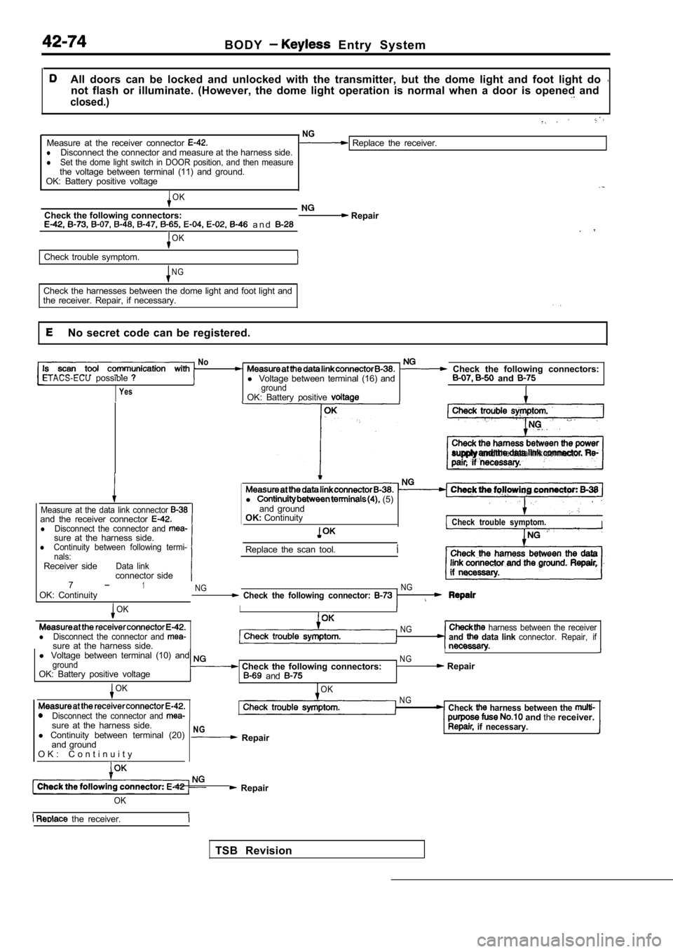
All doors can be locked and unlocked with the transmitter, but the dome light and foot light do not flash or illuminate. (However, the dome light operation is normal when a door is opened and
closed.)
NGMeasure at the receiver connector Replace the receiver.lDisconnect the connector and measure at the harness side.lSet the dome light switch in DOOR position, and then measurethe voltage between terminal (11) and ground.
OK: Battery positive voltage
OK
Check the following connectors: Repair a n d .OK
Check trouble symptom.
N G
Check the harnesses between the dome light and foot light and
the receiver. Repair, if necessary.
No secret code can be registered.
NoCheck the following connectors:ETACS-ECUpossiblel Voltage between terminal (16) and and
YesgroundOK: Battery positive
supply and the data link connector.
Measure at the data link connector and the receiver connector lDisconnect the connector and sure at the harness side.lContinuity between following termi-
nals:
Receiver sideData linkconnector side
l (5)
and ground
OK: Continuity
Check trouble symptom.I
Replace the scan tool.
71OK: ContinuityNG NG Check the following connector:
OKI
lDisconnect the connector and sure at the harness side.
NG harness between the receiverand data link connector. Repair, if
l
Voltage between terminal (10) and I
groundNG
OK: Battery positive voltage Check the following connectors: Repair and
OK
Disconnect the connector and
OKNGCheck harness between the and thereceiver.
sure at the harness side.
l Continuity between terminal (20)
and ground
O K : C o n t i n u i t y
NG Repair if necessary.
Repair
TSB Revision
OK
the receiver.
Page 1899 of 2103

B O D Y Entry System
When all doors are locked with the transmitter, the theft-alarm system is not set. (The SECURITY
indicator doesn’t illuminate, and the alarm doesn’t function.)
When all doors are locked with the key, is the theft-alarm systemCheck the theft-alarm to GROUP 54 set?
System.)
Yes ,
Check the following connectors: and NG Repair
OK
Check trouble symptom.
NG NG
Disconnect the receiver connector measure harnessCheck the harness wire between the receiver and ETA CS-ECU.side.l Voltage between the terminal (15) and ground
OK: (Pulse output)’
OK
Replace the receiver.1
NOTEl : Using an oscilloscope
When the PANIC switch of the transmitter is pressed , the headlights do not flash and the horns
do not sound. (However, the theft-alarm functions n ormally.)
with theft-alarm system>
[Comment]When the PANIC switch is pressed, the receiver sends a PANIC signal to ETACS-ECU. Then the ECU flashes the headlights and sounds
the horns intermittently for approx. three minutes.
The headlights and horns share an operation circuit with the theft-alarm system. Because of this, if the theft-alarm system functions normally,
the
harness between the receiver and the ETACS-ECU mav be defective.
N GCheck the operation of the theft-alarm system. (Refer to GROUP Carry out troubleshooting for the theft-alarm 54 Theft-alarm System.) 1’
Repair
OK
Check trouble 1
NG
harness
side.
l Voltage between the terminal (15) and ground
OK: (Pulse output)
OK
the receiver.
N GCheck the harness wire between the receiver and ETA CS-ECU.
NOTEl : Using an oscilloscope
TSB Revision
Page 1900 of 2103

42-76B O D Y Entry System
Terminal No.
1
2
6
7
9
10
11
12
13
14
15
20
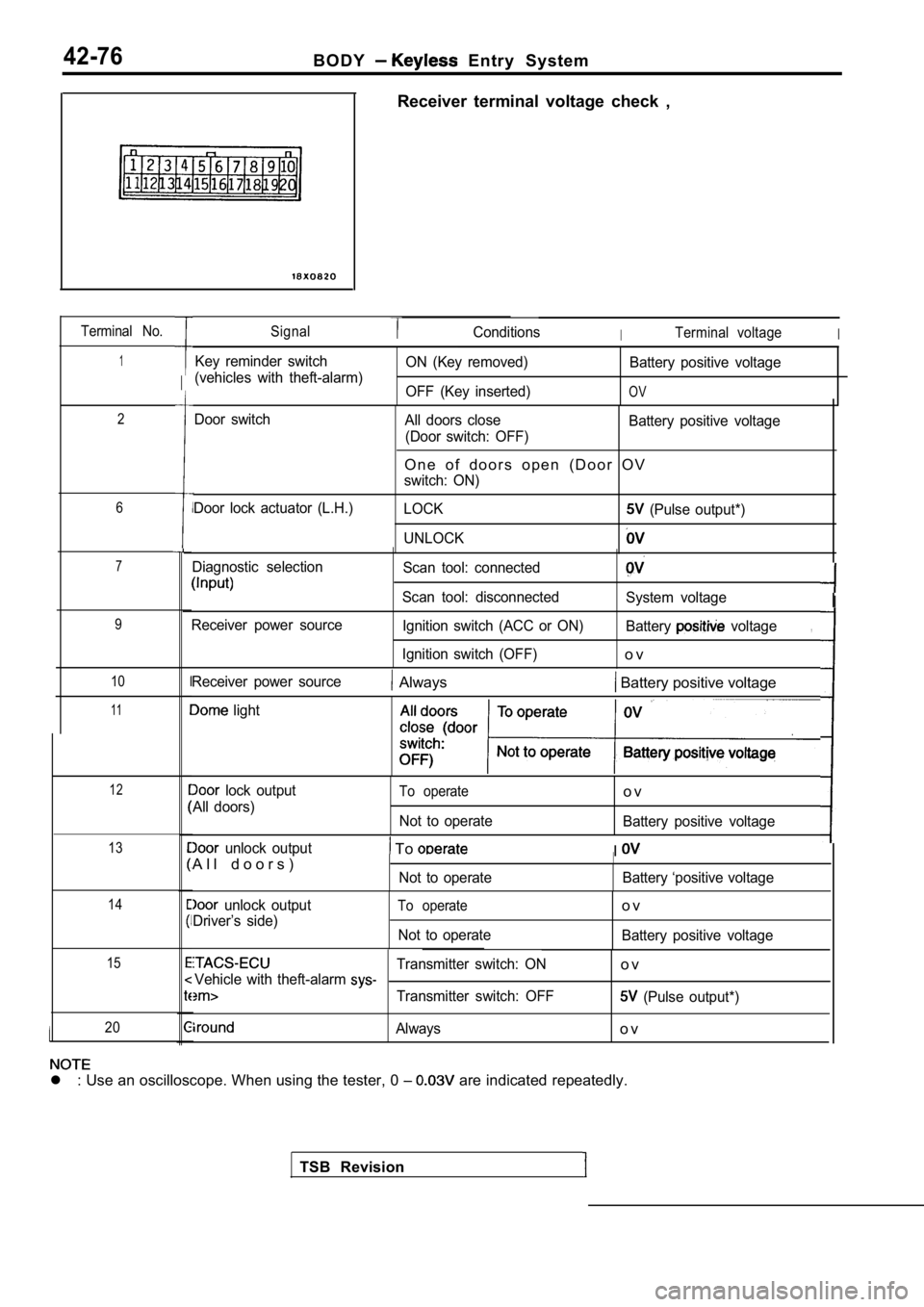
Receiver terminal voltage check ,
SignalConditionsITerminal voltageI
Key reminder switch
(vehicles with theft-alarm) ON (Key removed)
OFF (Key inserted) Battery positive voltage
OV
Door switch
Door lock actuator (L.H.) All doors close
(Door switch: OFF) Battery positive voltage
O n e o f d o o r s o p e n ( D o o r O V
switch: ON)
LOCK
(Pulse output*)
UNLOCK
Diagnostic selection
Receiver power source Scan tool: connected
Scan tool: disconnected Ignition switch (ACC or ON)
Ignition switch (OFF)
System voltage
Battery
voltage
o v
,
TSB Revision
Receiver power source Always Battery positive voltage
light
lock output
All doors)To operate
Not to operate
o v
Battery positive voltage
unlock output
A l l d o o r s ) To
Not to operate
II
Battery ‘positive voltage
unlock output
Driver’s side)To operate
Not to operate
o v
Battery positive voltage
Transmitter switch: ONo vVehicle with theft-alarm
Transmitter switch: OFF (Pulse output*)
Alwayso v
l : Use an oscilloscope. When using the tester, 0
are indicated repeatedly.
I