1990 MITSUBISHI SPYDER light
[x] Cancel search: lightPage 2022 of 2103
![MITSUBISHI SPYDER 1990 Service Repair Manual SRS Troubleshooting
Code or 55 Front passenger’s air bag module
(Squib ignition drive
system Probable cause
[Comment]l
Malfunction of SRS-ECUThese diagnostic trouble codes are MITSUBISHI SPYDER 1990 Service Repair Manual SRS Troubleshooting
Code or 55 Front passenger’s air bag module
(Squib ignition drive
system Probable cause
[Comment]l
Malfunction of SRS-ECUThese diagnostic trouble codes are](/manual-img/19/57345/w960_57345-2021.png)
SRS Troubleshooting
Code or 55 Front passenger’s air bag module
(Squib ignition drive
system Probable cause
[Comment]l
Malfunction of SRS-ECUThese diagnostic trouble codes are output when a sh ort-circuit or open circuit occurs in the squib ignition drive circuit inside the SRS-ECU.
Insulating tape
Battery cable
Caution
Turn the ignition key to the “LOCK” position, disco nnect
the negative battery cable and tape the terminal.
Wait at least 60 seconds after disconnecting the battery
cable before doing any further work. (Refer to
Replace the SRS-ECU.
lightwarning
TSB Revision
SRS WARNING LIGHT INSPECTION
1. Check that the warning ‘light
ignition switch is in the ON position.
2.Check that it illuminates for approximately 7 and
then switches off.
3.If the above is not the case, check the diagnostic trouble
codes.
Page 2023 of 2103
SRS Troubleshooting
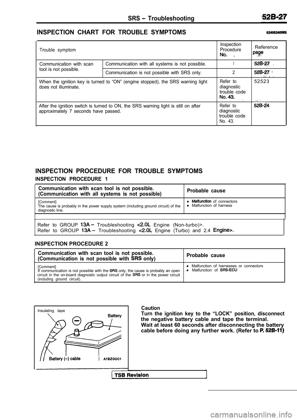
INSPECTION CHART FOR TROUBLE SYMPTOMS
Trouble symptom
Communication with scanCommunication with all systems is not possible.
tool is not possible. Communication is not possible with SRS only.
When the ignition key is turned to “ON” (engine sto pped), the SRS warning light
does not illuminate.
After the ignition switch is turned to ON, the SRS warning light is still on after
approximately 7 seconds have passed. Inspection
Procedure
Reference
,
1 .
2 ,
Refer to5 2 5 2 3
diagnostic
trouble code
Refer to
diagnostic
trouble code
No. 43.
INSPECTION PROCEDURE FOR TROUBLE SYMPTOMS
INSPECTION PROCEDURE 1
Communication with scan tool is not possible.
(Communication with all systems is not possible) Probable cause
[Comment]l of connectors
The cause is probably in the power supply system (i ncluding ground circuit) of thel
Malfunction of harness
diagnostic line.
Refer to GROUP
Troubleshooting Engine (Non-turbo)>.
Refer to GROUP
Troubleshooting Engine (Turbo) and 2.4
INSPECTION PROCEDURE 2
Communication with scan tool is not possible.
(Communication is not possible with
only) Probable cause
[Comment]l
Malfunction of harnesses or connectors
If communication is not possible with the only, the cause is probably an open l
Malfunction of circuit in the on-board diagnostic output circuit o f the or in the power circuit(including ground circuit).
Insulating tapeCaution
Turn the ignition key to the “LOCK” position, disco nnect
the negative battery cable and tape the terminal.
Wait at least 60 seconds after disconnecting the ba ttery
cable before doing any further work. (Refer to
Page 2029 of 2103
SRS SRS Air BagControl Unit (SRS-ECU)
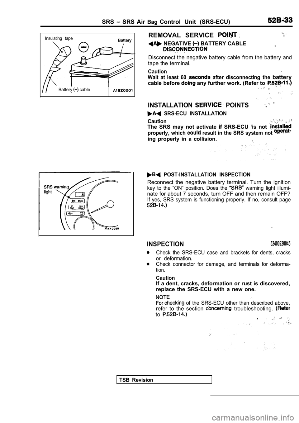
Insulating tape
Battery cable
REMOVAL SERVICE
NEGATIVE BATTERY CABLE
.
Disconnect the negative battery cable from the batt ery and
tape the terminal.
Caution
Wait at least 60 after disconnecting the battery
cable before any further work. (Refer to ,
INSTALLATION POINTS.
SRS-ECU INSTALLATION
Caution
The SRS may not activate SRS-ECU ‘is not
properly, which result in the SRS system not
ing properly in a collision.
POST-INSTALLATION INSPECTION
Reconnect the negative battery terminal. Turn the i gnition
key to the “ON” position. Does the warning light illumi-
nate for about 7 seconds, turn OFF and then remain OFF?
If yes, SRS system is functioning properly. If no, consult page
INSPECTION52400220045
Check the SRS-ECU case and brackets for dents, crac ks
or deformation.
Check connector for damage, and terminals for defor ma-
tion.
Caution
If a dent, cracks, deformation or rust is discovered,
replace the SRS-ECU with a new one.
of the SRS-ECU other than described above,
refer to the section troubleshooting.
to,
TSB Revision
Page 2034 of 2103
SRS Air Bag Modules. and Clock Spring
SRSlight
0 0 0 0 0 0 5 5
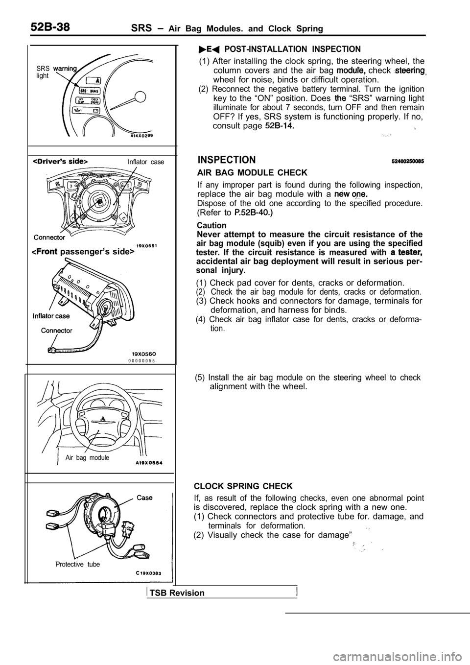
POST-INSTALLATION INSPECTION
(1) After installing the clock spring, the steering wheel, the
column covers and the air bag
check
wheel for noise, binds or difficult operation.
(2) Reconnect the negative battery terminal. Turn t he ignition
key to the “ON” position. Does “SRS” warning light
illuminate for about 7 seconds, turn OFF and then r emain
OFF? If yes, SRS system is functioning properly. If no,
consult page
INSPECTION
AIR BAG MODULE CHECK
If any improper part is found during the following inspection,
replace the air bag module with a
Dispose of the old one according to the specified p rocedure.
(Refer to
Caution
Never attempt to measure the circuit resistance of the
air bag module (squib) even if you are using the specified
tester. If the circuit resistance is measured with
accidental air bag deployment will result in seriou s per-
sonal injury.
(1) Check pad cover for dents, cracks or deformation.
(2)Check the air bag module for dents, cracks or defor mation.
(3) Check hooks and connectors for damage, terminal s for
deformation, and harness for binds.
(4) Check air bag inflator case for dents, cracks o r deforma-
tion.
Air bag module
Protective tube
(5) Install the air bag module on the steering whee l to check
alignment with the wheel.
CLOCK SPRING CHECK
If, as result of the following checks, even one abn ormal point
is discovered, replace the clock spring with a new one.
(1) Check connectors and protective tube for. damag e, and
terminals for deformation.
(2) Visually check the case for damage”
TSB Revision
Page 2041 of 2103
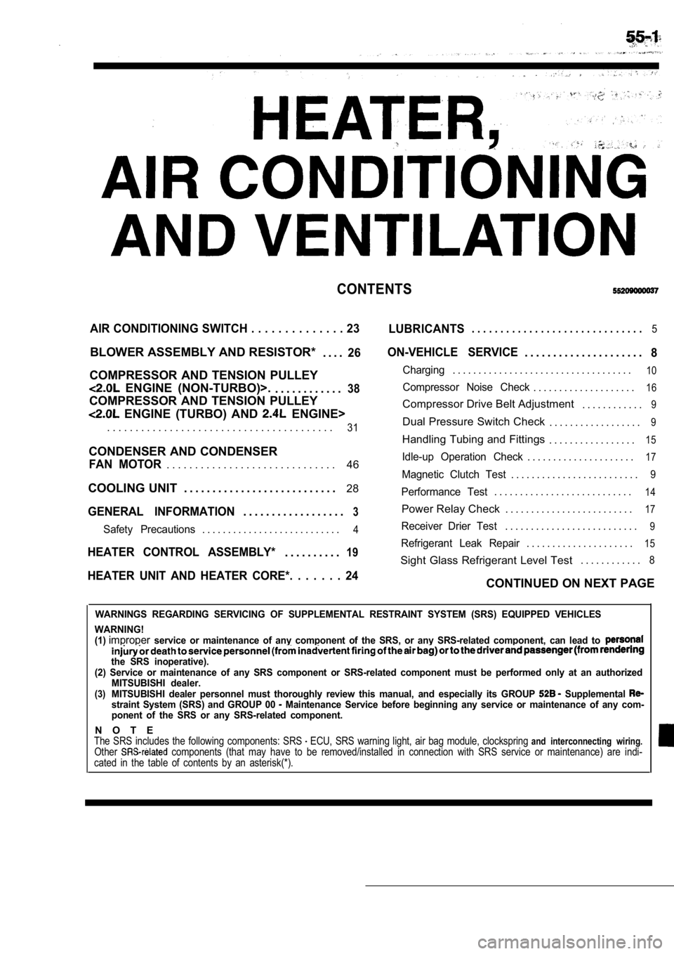
CONTENTS
AIR CONDITIONING SWITCH . . . . . . . . . . . . . . 23
LUBRICANTS. . . . . . . . . . . . . . . . . . . . . . . . . . . . . .5
BLOWER ASSEMBLY AND RESISTOR*
. . . .26
COMPRESSOR AND TENSION PULLEY
ENGINE (NON-TURBO)>.. . . . . . . . . . . .38
COMPRESSOR AND TENSION PULLEY
ENGINE (TURBO) AND ENGINE>
ON-VEHICLE SERVICE. . . . . . . . . . . . . . . . . . . . .8
Charging. . . . . . . . . . . . . . . . . . . . . . . . . . . . . . . . . . .10
Compressor Noise Check. . . . . . . . . . . . . . . . . . . .16
Compressor Drive Belt Adjustment . . . . . . . . . . . .9
. . . . . . . . . . . . . . . . . . . . . . . . . . . . . . . . . . . . . . . .31Dual Pressure Switch Check. . . . . . . . . . . . . . . . . .9
Handling Tubing and Fittings. . . . . . . . . . . . . . . . .15
CONDENSER AND CONDENSER
46Idle-up Operation Check. . . . . . . . . . . . . . . . . . . . .17FAN MOTOR. . . . . . . . . . . . . . . . . . . . . . . . . . . . . .Magnetic Clutch Test. . . . . . . . . . . . . . . . . . . . . . . . .9
COOLING UNIT . . . . . . . . . . . . . . . . . . . . . . . . . . . 28
GENERAL INFORMATION3. . . . . . . . . . . . . . . . . .
Performance Test. . . . . . . . . . . . . . . . . . . . . . . . . . .14
Power Relay Check . . . . . . . . . . . . . . . . . . . . . . . . .17
Safety Precautions. . . . . . . . . . . . . . . . . . . . . . . . . . .4Receiver Drier Test. . . . . . . . . . . . . . . . . . . . . . . . . .9
. . . . . . . . . . . . . . . . . . . . .15HEATER CONTROL ASSEMBLY*19Refrigerant Leak Repair. . . . . . . . . .
Sight Glass Refrigerant Level Test . . . . . . . . . . . .8
HEATER UNIT AND HEATER CORE*. . . . . . . 24CONTINUED ON NEXT PAGE
WARNINGS REGARDING SERVICING OF SUPPLEMENTAL RESTRA
INT SYSTEM (SRS) EQUIPPED VEHICLES
WARNING!
(1)
improperservice or maintenance of any component of the SRS, or any SRS-related component, can lead to
the SRS inoperative).
(2) Service or maintenance of any SRS component or SRS-related component must be performed only at an authorized
MITSUBISHI dealer.
(3)MITSUBISHI dealer personnel must thoroughly review this manual, and especially its GROUP Supplemental straint System (SRS) and GROUP 00 Maintenance Service before beginning any service or maintenance of any com-
ponent of the SRS or any SRS-related component.
N O T EThe SRS includes the following components: SRS ECU, SRS warning light, air bag module, clocksprin g and interconnecting wiring.Other components (that may have to be removed/installed in connection with SRS service or maintenance) are indi-
cated in the table of contents by an asterisk(*).
Page 2054 of 2103
HEATER, AIR
AND VENTILATION On-vehicle Service
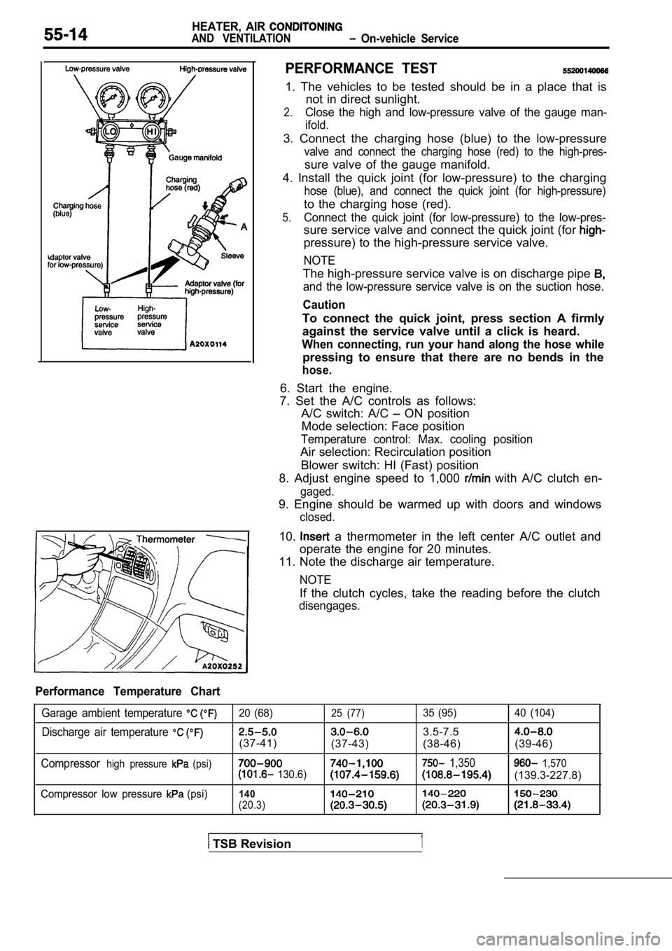
PERFORMANCE TEST
1. The vehicles to be tested should be in a place that is
not in direct sunlight.
2.Close the high and low-pressure valve of the gauge man-
ifold.
3. Connect the charging hose (blue) to the low-pres sure
valve and connect the charging hose (red) to the high-pres-
sure valve of the gauge manifold.
4. Install the quick joint (for low-pressure) to th e charging
hose (blue), and connect the quick joint (for high- pressure)
to the charging hose (red).
5.Connect the quick joint (for low-pressure) to the low-pres-
sure service valve and connect the quick joint (for
pressure) to the high-pressure service valve.
NOTE
The high-pressure service valve is on discharge pip e
and the low-pressure service valve is on the suction hose.
Caution
To connect the quick joint, press section A firmly
against the service valve until a click is heard.
When connecting, run your hand along the hose while
pressing to ensure that there are no bends in the
hose.
6. Start the engine.
7. Set the A/C controls as follows: A/C switch: A/C
ON position
Mode selection: Face position
Temperature control: Max. cooling position
Air selection: Recirculation position
Blower switch: HI (Fast) position
8. Adjust engine speed to 1,000
with A/C clutch en-
gaged.
9. Engine should be warmed up with doors and window s
closed.
10. a thermometer in the left center A/C outlet and
operate the engine for 20 minutes.
11. Note the discharge air temperature.
NOTE
If the clutch cycles, take the reading before the c lutch
disengages.
Performance Temperature Chart
Garage ambient temperature 20 (68)25 (77)35 (95) 40 (104)
Discharge air temperature 3.5-7.5
(37-41)
(37-43) (38-46) (39-46)
Compressorhigh pressure (psi) 1,350 1,570 130.6)(139.3-227.8)
Compressor low pressure (psi)140
(20.3)
TSB Revision1
Page 2057 of 2103
HEATER, AIR
AND VENTILATION On-vehicle Service
IDLE-UP OPERATION CHECK
1,Before inspection and adjustment, set the f&w-
ing condition:
lEngine coolant temperature:
lLights, electric cooling fan and accessories: Set t o
OFF
lTransmission: Neutral (N or for vehicles with
l Steering wheel:
2. Check whether or not the idling speed is the sta ndard
value.
Blower relay
Standard value:
100
Engine (Turbo) and Engine>
100 Engine (Non-turbo)>
3. When the
is running after turning the A/C switch
to ON, and the blower switch to the MH or HI positi on,
check to be sure that the idle speed is at the stan dard
value.
Standard value: (in Neutral)
NOTE
Idle speed is controlled by the system and is not
adjustable. If, idle speed is not within specifications, check
the system.
Engine (Non-turbo)>: Refer to GROUP On-
vehicle Service.)
Engine (Turbo)>: Refer to GROUP On-vehicle
Service.)
Engine>: Refer to GROUP On-vehicle Ser-
vice.)
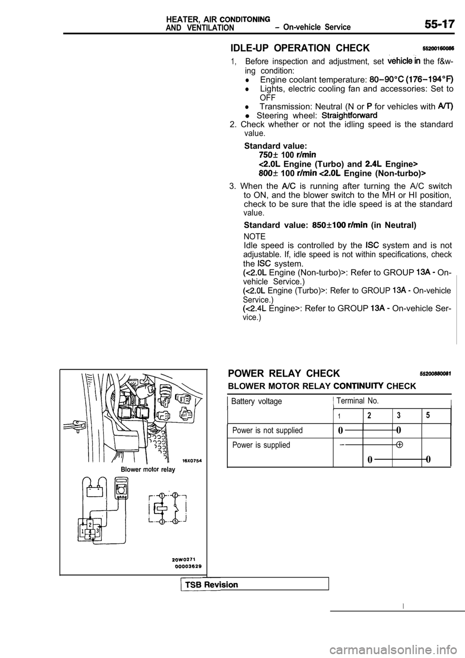
POWER RELAY CHECK
BLOWER MOTOR RELAY CHECK
Battery voltage Terminal No.III
1235
Power is not supplied
Power is supplied0 0
0 0
Page 2061 of 2103
Air-recirculation position
HEATER, AIR
AND VENTILATION Heater Control Assembly
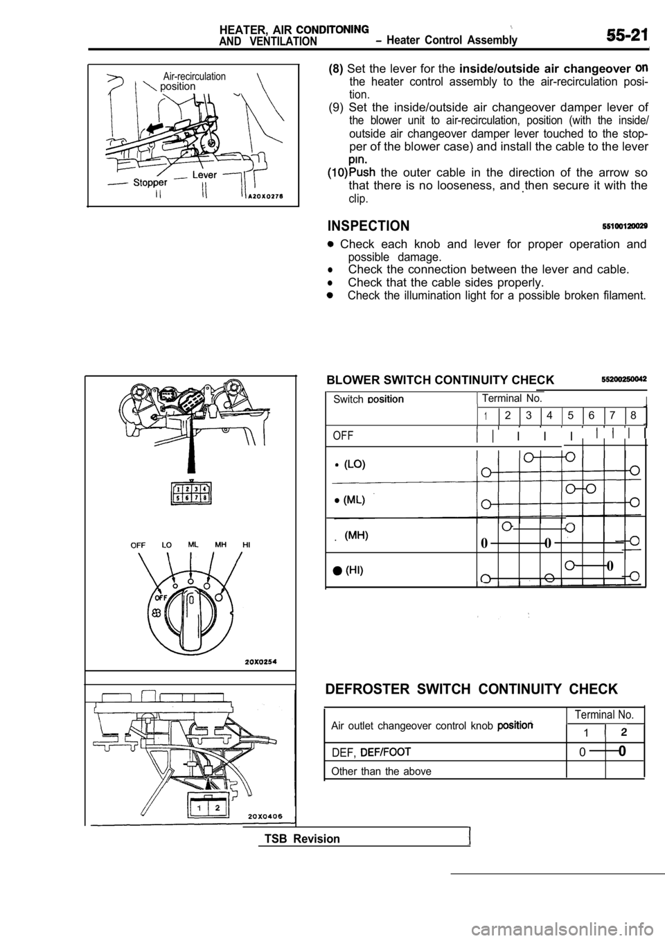
(8)Set the lever for the inside/outside air changeover
the heater control assembly to the air-recirculatio n posi-
tion.
(9) Set the inside/outside air changeover damper le ver of
the blower unit to air-recirculation, position (with the inside/
outside air changeover damper lever touched to the stop-
per of the blower case) and install the cable to the lever
the outer cable in the direction of the arrow so
that there is no looseness, and then secure it with the
.
clip.
INSPECTION
Check each knob and lever for proper operation and
possible damage.
lCheck the connection between the lever and cable.
lCheck that the cable sides properly.
Check the illumination light for a possible broken filament.
BLOWER SWITCH CONTINUITY CHECK
Switch Terminal No.I
12 3 4 5 6 7 8
OFF I I I
.0 0
0
TSB Revision
DEFROSTER SWITCH CONTINUITY CHECK
Terminal No.Air outlet changeover control knob 1
DEF,
Other than the above
00