Page 1391 of 2103
AUTOMATIC TRANSAXLE
-Transfer
TRANSFER23300670017
DISASSEMBLY AND
39
Lubricate all internal parts
with gear oilduring reassembly.
Disassemblv .
1.Cover 2. Cover gasket 3. Extension housing assembly
4. Oil guide
5. Transfer case sub assembly
6. ,
c a s e sub
REASSEMBLYSERVICE POINTS
CASE ADAPTER ASSEMBLY
INSTALLATION
Apply a
light and uniform of machine or red
lead to the driven bevel gear teeth
sides) using
a brush.
TSB Revision
Page 1397 of 2103
AUTOMATIC TRANSAXLE
-Transfer Case Adapter
2
4
DRIVEN GEAR ASSEMBLY
Using a press, the bevel gear
OUTER RACE REMOVAL
(1) Remove the outer race, lightly with a screwdriver,
etc.
TAPER ROLLER BEARING REMOVAL
REASSEMBLY SERVICE POINTS
TAPER ROLLER BEARING INSTALLATION
.
RevisionI
Page 1458 of 2103
AUTOMATIC TRANSAXLE O V E R H A U L
Pushdown to
Piston
Piston
return
spring
shaft
retainer
assembly
(8) To install input shaft hub assembly to overdrive/reverse
piston, rotate input’ shaft hub to align
overdrive/reverse piston and push down by hand.
,
(7) Install input hub tapered with snap’ ring pliers.
(8) Install underdrive clutch piston.,
(9) Install piston return spring. Installer
Coat Installer inner surface lightly with petroleum ’ jelly.
Place Installer into Input clutch assembly
inside diameter facing up.
underdrive spring retainer.
Remove Installer
TSB Revision
Page 1524 of 2103

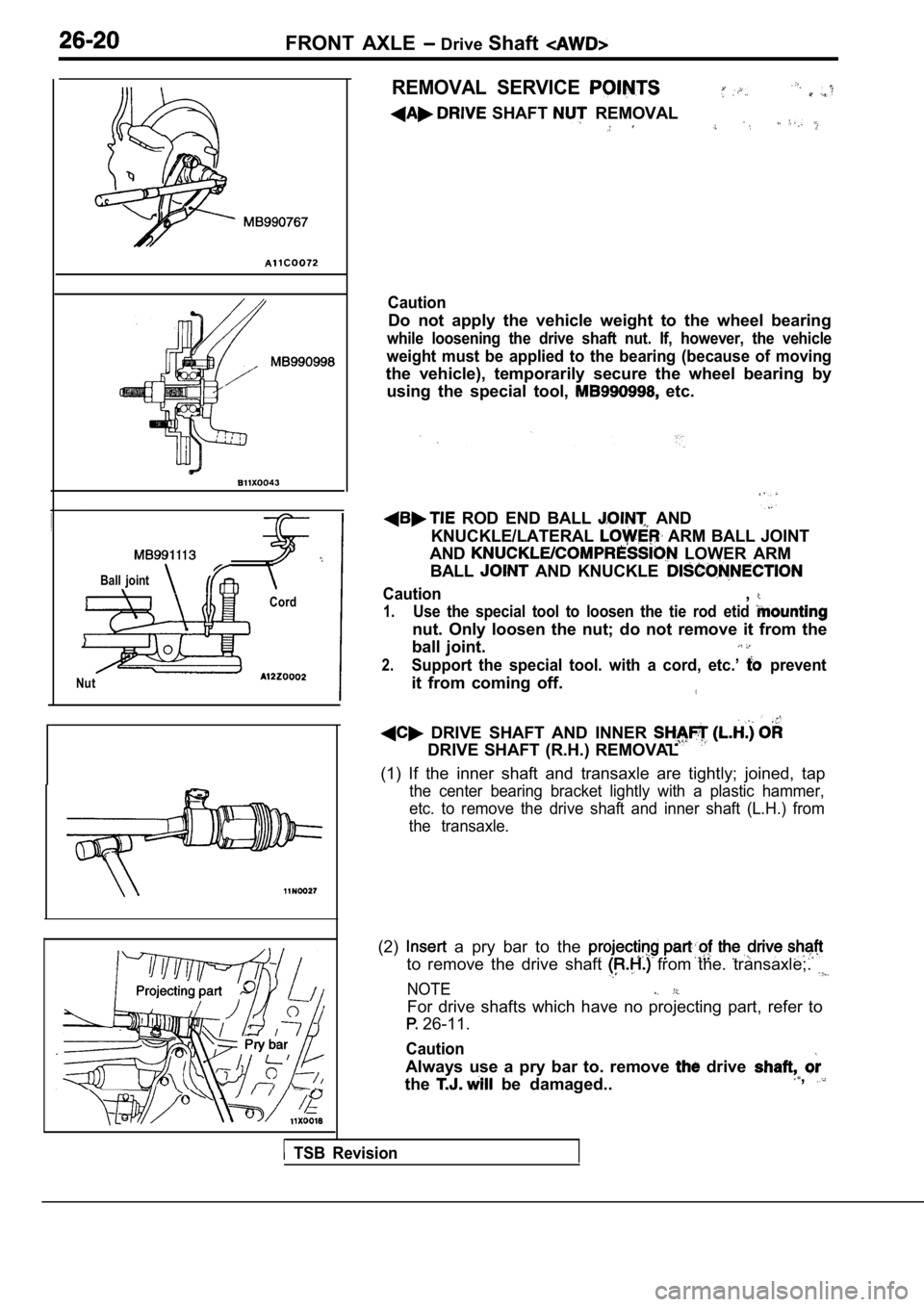
FRONT AXLE Drive Shaft
Ball joint
Cord
Nut
REMOVAL SERVICE
SHAFT REMOVAL
Caution
Do not apply the vehicle weight to the wheel bearin g
while loosening the drive shaft nut. If, however, the vehicle
weight must be applied to the bearing (because of m oving
the vehicle), temporarily secure the wheel bearing by
using the special tool,
etc.
ROD END BALL AND
KNUCKLE/LATERAL
ARM BALL JOINT
AND
LOWER ARM
BALL
AND KNUCKLE
Caution,
1.Use the special tool to loosen the tie rod etid
nut. Only loosen the nut; do not remove it from the
ball joint.
2.Support the special tool. with a cord, etc.’ prevent
it from coming off.
DRIVE SHAFT AND INNER
DRIVE SHAFT (R.H.) REMOVAL
(1) If the inner shaft and transaxle are tightly; j oined, tap
the center bearing bracket lightly with a plastic h ammer,
etc. to remove the drive shaft and inner shaft (L.H .) from
the transaxle.
(2) a pry bar to the
to remove the drive shaft from the. transaxle;.
NOTE
For drive shafts which have no projecting part, ref er to
26-11.
Caution
Always use a pry bar to. remove drive
the
be damaged..,
TSB Revision
Page 1595 of 2103
POWER PLANT MOUNT Transaxle
TRANSAXLE MOUNTING
REMOVAL AND INSTALLATION
and Post-installation OperationlAir Cleaner Assembly Removal and Installationl Battery Removal and Installationl Engine Roll Stopper, Centermember AssemblyRemoval and Installation (Refer to
Engine (Non-turbo)> Engine (Turbo) and Engine>
69 Nm3.
NOTEl
1. Battery bracket
2. Evaporative emission canister
Engine (Turbo)> (Refer to
GROUP 17 Evaporative Emission
Control System)
3. Evaporative emission canister hold- er assembly
Engine (Turbo)>
(Refer to GROUP 17 Evapora-
tive Emission Control System) 4. Battery stay
5.
mount insulator mounting
6. Transaxle mount bracket
7. Transaxle mount stopper
REMOVAL SERVICE POINT
TRANSAXLE MOUNT BRACKET REMOVAL
Slightly lower the transaxle, and then remove the t ransaxle
mount bracket.
TSBRevision
Page 1602 of 2103

FRONT SUSPENSION General Information
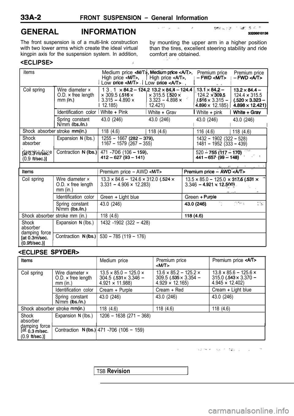
GENERAL INFORMATION
The front suspension is of a multi-link constructionby mounting the upper arm in a higher position
with two lower arms which create the ideal virtual than the tires, excellent steering stability and ride
kingpin axis for the suspension system. In addition ,comfort are obtained.
itemsMedium price
High price
Premium price
I
Premium priceHigh price I Low Low ,I
Coil spring
Wire diameter
O.D. free length
1 3 . 1
309.5 315.5 mm3.315 4.890 3.323 4.898
124.2
3.315
I 12.185) 12.421) 12.185)
Identification color White Pink White GravIWhite pink
124.4 315.5
Spring constant 43.0 (246) 43.0 (246)
I
43.0 (246)N/mmI
43.0 (246)
I
Shock absorberstroke118 (4.6) 118(4.6)116 (4.6) 118 (4.6)
Shock Expansion
(Ibs.)1255 16671432 1902(322 528)
absorber 1167 1579(267355)1481 1952 (333 439)
damping force
Contraction471-706(106520
(0.9
Premium price AWD
Coilspring Wire diameter 13.3 84.6 124.6 312.013.5 85.0 125.0
O.D. free length 3.331 4.906 12.283)3.346
mm (in.)
Identification color Green Light blueGreen
Spring constant43.0 (246)
N/mm
Shock absorber stroke mm (in.)118 (4.6)
ShockExpansion (Ibs.)
1432 -1902 (322 428)
absorber
damping force
Contraction530 785 (119 176)
TSBRevision
Medium price Premium pricePremium price
Coil spring Wire diameter 13.5 85.0 125.0 13.6 85.2 125.2 13.8 85.6 125.6
O.D. free length304.5 3.346 309.5 3.354 315.0 3.370
mm (in.) 4.921 11.988)
4.929 12.165)4.945 12.402)
Identification color Cream
PurpleCream RedCream Light blue
Spring constant 43.0 (246) 43.0 (246) 43.0 (246)
N/mm
Shock absorber stroke 118 (4.6) 118 (4.6) 118 (4.6)
ShockExpansion (Ibs.)
1206 1638 (271 368)
absorber
damping force
[atContraction 471 -706 (106 159)
(0.9
Page 1639 of 2103

B R A K E
S Y S T E M
CONTENTS
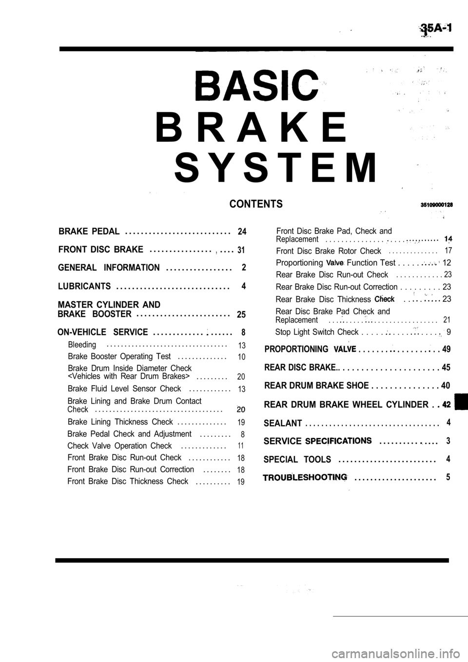
BRAKE PEDAL. . . . . . . . . . . . . . . . . . . . . . . . . . .24
FRONT DISC BRAKE. . . . . . . . . . . . . . . .,. . . .31
GENERAL INFORMATION. . . . . . . . . . . . . . . . .2
LUBRICANTS. . . . . . . . . . . . . . . . . . . . . . . . . . . . .4
MASTER CYLINDER AND
BRAKE BOOSTER. . . . . . . . . . . . . . . . . . . . . . . .25
ON-VEHICLE SERVICE
. . . . . . . . . . . . .. . . . . .8
Bleeding. . . . . . . . . . . . . . . . . . . . . . . . . . . . . . . . . .13
Brake Booster Operating Test. . . . . . . . . . . . . .10
Brake Drum Inside Diameter Check
. . . . . . . . .20
Brake Fluid Level Sensor Check. . . . . . . . . . . .13
Brake Lining and Brake Drum Contact
Check. . . . . . . . . . . . . . . . . . . . . . . . . . . . . . . . . . . .
Brake Lining Thickness Check. . . . . . . . . . . . . .19
Brake Pedal Check and Adjustment. . . . . . . . .8
Check Valve Operation Check. . . . . . . . . . . . .11
Front Brake Disc Run-out Check. . . . . . . . . . . .18
Front Brake Disc Run-out Correction. . . . . . . .18
Front Brake Disc Thickness Check. . . . . . . . . .19
Front Disc Brake Pad, Check and
Replacement. . . . . . . . . . . . . . . . . . .
Front Disc Brake Rotor Check. . . . . . . . . . . . . .17
Proportioning Function Test . . . . . 12
Rear Brake Disc Run-out Check. . . . . . . . . . . . 23
Rear Brake Disc Run-out Correction . . . . . . . . . 23
Rear Brake Disc Thickness
. . . 23
Rear Disc Brake Pad Check and
Replacement. . . . . . . . . . . . . . . . . . . . . . . . . 21
Stop Light Switch Check . . . . . . . . . . . . . 9
PROPORTIONING . . . . . . . . . . . . . . . . 49
REAR DISC BRAKE.. . . . . . . . . . . . . . . . . . . . . . 45
REAR DRUM BRAKE SHOE . . . . . . . . . . . . . . . 40
REAR DRUM BRAKE WHEEL CYLINDER .
SEALANT. . . . . . . . . . . . . . . . . . . . . . . . . . . . . . . . . .4
SERVICE. . . . . . . . . .. . . .3
SPECIAL TOOLS. . . . . . . . . . . . . . . . . . . . . . . . .4
. . . . . . . . . . . . . . . . . . . . .5
Page 1646 of 2103

BASIC BRAKE SYSTEM .,
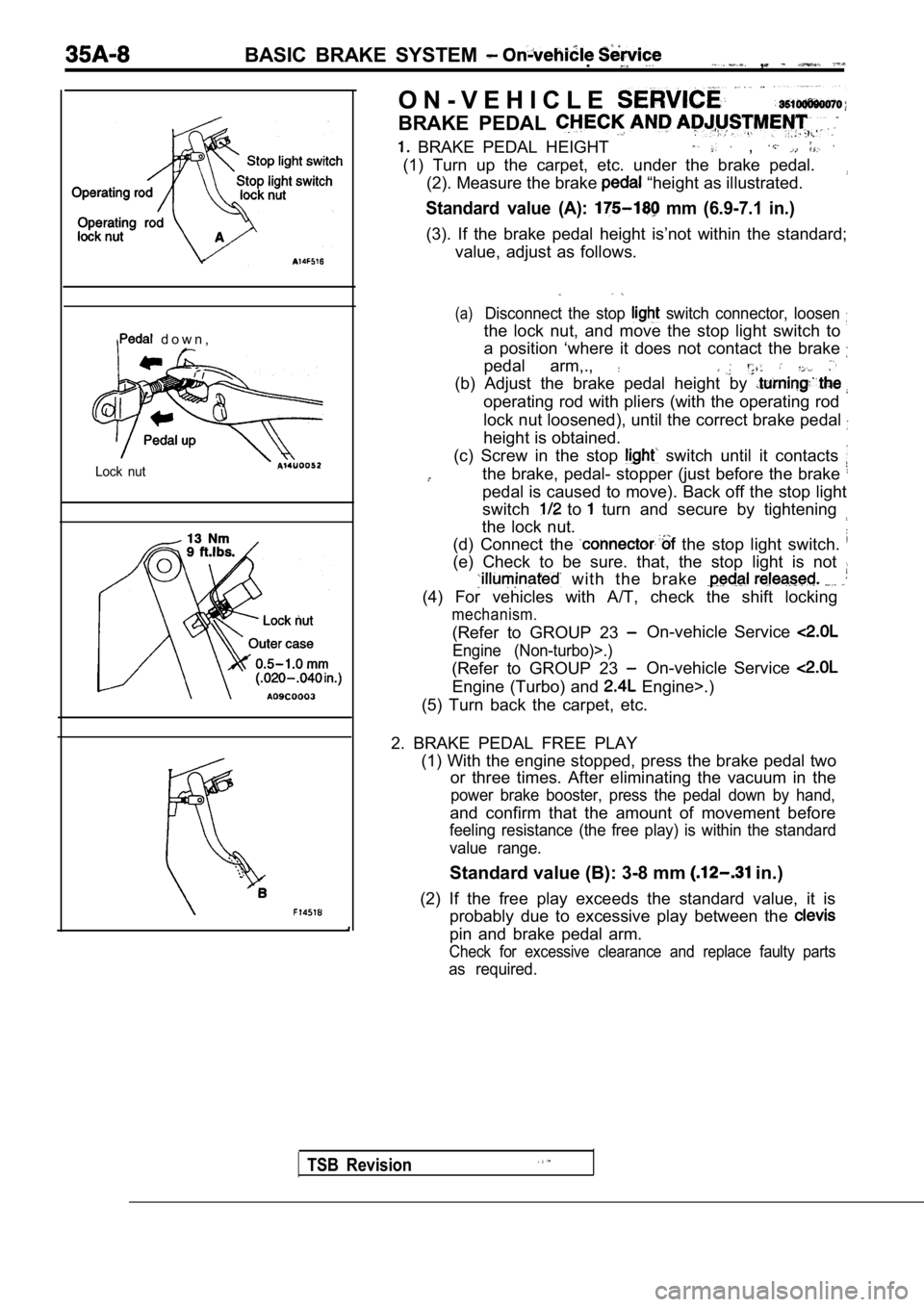
d o w n ,
Lock nut
TSB Revision
O N - V E H I C L E
BRAKE PEDAL
BRAKE PEDAL HEIGHT ,
(1) Turn up the carpet, etc. under the brake pedal.(2). Measure the brake
“height as illustrated.
Standard value (A): mm (6.9-7.1 in.)
(3). If the brake pedal height is’not within the st andard;
value, adjust as follows.
(a)Disconnect the stop switch connector, loosen
the lock nut, and move the stop light switch to
a position ‘where it does not contact the brake
pedal arm,.,
(b) Adjust the brake pedal height by
operating rod with pliers (with the operating rod
lock nut loosened), until the correct brake pedal
height is obtained.
(c) Screw in the stop
switch until it contacts
the brake, pedal- stopper (just before the brake
pedal is caused to move). Back off the stop light
switch
to turn and secure by tightening
the lock nut.
(d) Connect the
the stop light switch.
(e) Check to be sure. that, the stop light is not
with the brake
(4) For vehicles with A/T, check the shift locking
mechanism.
(Refer to GROUP 23 On-vehicle Service
Engine (Non-turbo)>.)
(Refer to GROUP 23 On-vehicle Service
Engine (Turbo) and Engine>.)
(5) Turn back the carpet, etc.
2. BRAKE PEDAL FREE PLAY (1) With the engine stopped, press the brake pedal two
or three times. After eliminating the vacuum in the
power brake booster, press the pedal down by hand,
and confirm that the amount of movement before
feeling resistance (the free play) is within the st andard
value range.
Standard value (B): 3-8 mm in.)
(2) If the free play exceeds the standard value, it is
probably due to excessive play between the
pin and brake pedal arm.
Check for excessive clearance and replace faulty pa rts
as required.