Page 1107 of 2103
AUTOMATIC TRANSAXLE
ENGINE (TURBO) AND ENGINE> Lock
LOCK
I N S T A L L A T I O N
Secure the section between the metals of the
and key interlock cable with the of the steering cover
assembly.
Caution ,
Do not change the routing of shift lock cable to the
lever assembly. .
LOCK CABLE (SELECTOR LEVER SIDE)
INSTALLATION
(1) Place the selector fever in position
(2) Fasten the shift lock cable’ at the position where the end
of the shift lock cable is
above the red marking.
LEVER
I N S T A L L A T I O N
(1) Install the key interlock cable on the lock cam .
(2) Install the spring and washer of the key interl ock cable
as shown.
(3) While lightly pushing the cable coupling portio n of the
cam in-the direction A, tighten the nut to fasten the
key interlock cable. .
Check the cable assemblies for function and for dam
age.
TSB Revision
Page 1117 of 2103
AUTOMATIC TRANSAXLE
ENGINE AND Transaxle
Pry barTransaxle
S H A F T R E M O V A L
(1) a pry bar between the transaxle case drive
shaft, and then pry the drive shaft from the transaxle.
Caution
1.Use a pry bar to remove the shaft from the
B.J. assembly, or the may be dam-
aged. .
2.Do not insert the pry bar oil
may be damaged.
I
Use the special tool as a cover not fo let foreign
get into the transaxle case.
DRIVE SHAFT WITH INNER SHAFT
DISCONNECTION
(1) Lightly tap the center bracket with ham-
mer or similar tool to remove
shaft from the
transaxle.
(2) Suspend the removed. drive shaft with inner sha ft
wire so that‘there are no sharp bends in any of the
(3) Use the special a cover not to let foreign objects
g e t i n t o t h e t r a n s a x l e
Transmission jack
TSB
CONNECTING’ BOLTS/TRANSAXLE
ASSEMBLY MOUNTING BOLTS/TRANSAXLE
ASSEMBLY REMOVAL
(1)Use a transmission jack to support the transaxle as sembly.
Caution
Support the transaxle case side, not pan.
.
Page 1148 of 2103

AUTOMATIC TRANSAXLE
ENGINE (NON-TURBO)> Troubleshootihg
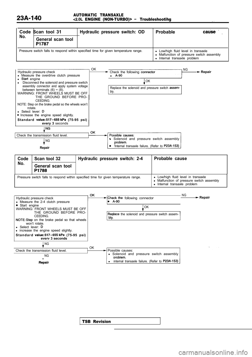
Code Scan tool 31Hydraulic pressure switch: ODProbable
No.General scan tool
Pressure switch falls to respond within specified time for given temperature range.
l Low/high fluid level in transaxle
l Malfunction of pressure switch assembly
l Internal transaxle problem
OKNGHydraulic pressure check Check the following Repair
l Measure the overdrive clutch pressure
l
l engine
l Disconnect the solenoid and pressure switchOK
assembly connector and apply system voltage
between terminals (6) (8).
WARNING: FRONT WHEELS MUST BE OFFReplace the solenoid and pressure switch bly.
THE GROUND BEFORE PRO-CEEDING.
NOTE: Step on the brake pedal so the wheels won’t rotate.
l Select lever: Increase the engine speed slightly.
S t a n d a r d
(75-95 psi)
every 3 seconds
Check the transmission fluid level.
NG
Repair
l Solenoid and pressure switch assembly
Internal transaxle failure. (Refer to
Code Scan tool 32 Hydraulic pressure switch: 2-4 Probable cause
No.General scan tool
TSB Revision
Pressure switch falls to respond within specified t
ime for given temperature range.l
Low/high fluid level in transaxle
l Malfunction of pressure switch assembly
l Internal transaxle problem
Hydraulic pressure check
l Measure the 2-4 clutch pressure
Start engine
following connector
WARNING: FRONT WHEELS MUST BE OFF THE GROUND BEFORE PRO-
CEEDING. on the brake pedal so that wheels
won’t rotate.
l Select lever:
l increase the engine speed slightly.
S t a n d a r d
(75-95 psi)
everv 3 seconds
NGOK
NG Repair
OK
the solenoid and pressure switch assem-
Check the transmission fluid level.
NG
Possible causes:
l Solenoid and pressure switch assembly
linternal transaxle failure. (Refer to
Page 1172 of 2103

AUTOMATIC TRANSAXLE
ENGINE (NON-TURBO)> On-vehicle Service
0
I
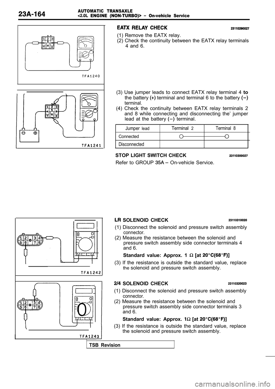
(1) Remove the EATX relay.
(2) Check the continuity between the EATX relay terminals
4 and 6.
(3) Use jumper leads to connect EATX relay terminal 4 to
the battery
terminal and terminal 6 to the battery
terminal.
(4) Check the continuity between EATX relay termina ls 2
and 8 while connecting and disconnecting the’ jumpe r
lead at the battery
terminal.
Jumperlead
Connected
Disconnected
Terminal2Terminal 8
STOP LIGHT SWITCH CHECK
Refer to GROUP
On-vehicle Service.
SOLENOID CHECK
(1) Disconnect the solenoid and pressure switch ass embly
connector.
(2) Measure the resistance between the solenoid and
pressure switch assembly side connector terminals 4
and 6.
Standard value: Approx. 1
[at
(3) If the resistance is outside the standard value , replace
the solenoid and pressure switch assembly.
SOLENOID CHECK
(1) Disconnect the solenoid and pressure switch ass embly
connector.
(2) Measure the resistance between the solenoid and
pressure switch assembly side connector terminals 3
and 6.
Standard value: Approx.
[at
(3) If the resistance is outside the standard value , replace
the solenoid and pressure switch assembly.
TSB Revision
Page 1174 of 2103

AUTOMATIC TRANSAXLE
ENGINE (NON-TURBO)> On-vehicle Service
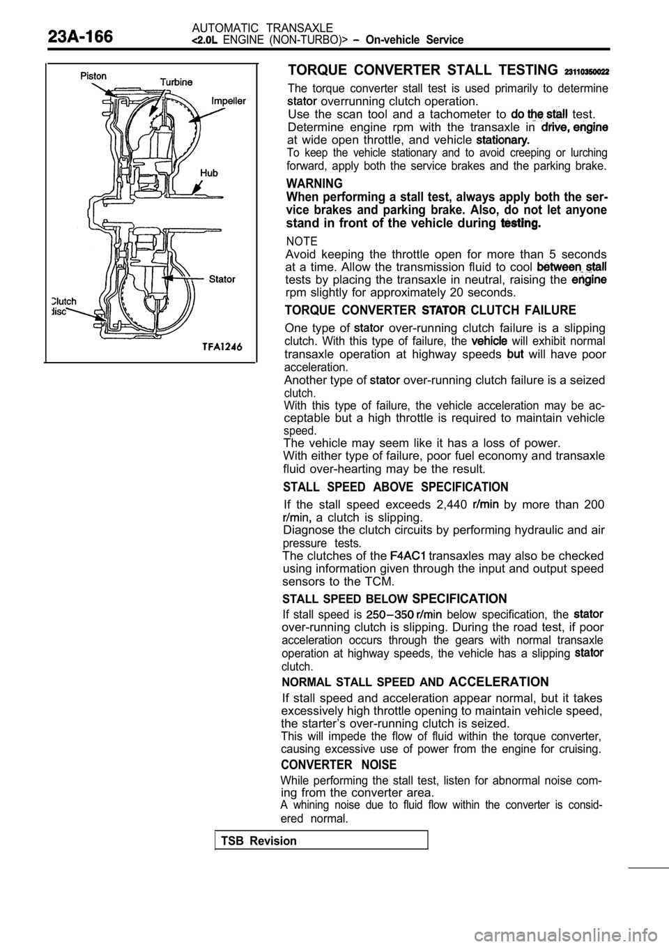
TORQUE CONVERTER STALL TESTING
The torque converter stall test is used primarily to determine
overrunning clutch operation.
Use the scan tool and a tachometer to
test.
Determine engine rpm with the transaxle in
at wide open throttle, and vehicle
To keep the vehicle stationary and to avoid creepin g or lurching
forward, apply both the service brakes and the parking brake.
WARNING
When performing a stall test, always apply both the ser-
vice brakes and parking brake. Also, do not let any one
stand in front of the vehicle during
NOTE
Avoid keeping the throttle open for more than 5 seconds
at a time. Allow the transmission fluid to cool
tests by placing the transaxle in neutral, raising the
rpm slightly for approximately 20 seconds.
TORQUE CONVERTER CLUTCH FAILURE
One type of over-running clutch failure is a slipping
clutch. With this type of failure, the will exhibit normal
transaxle operation at highway speeds will have poor
acceleration.
Another type of over-running clutch failure is a seized
clutch.
With this type of failure, the vehicle acceleration may be ac-
ceptable but a high throttle is required to maintai n vehicle
speed.
The vehicle may seem like it has a loss of power.
With either type of failure, poor fuel economy and transaxle
fluid over-hearting may be the result.
STALL SPEED ABOVE SPECIFICATION
If the stall speed exceeds 2,440 by more than 200
a clutch is slipping.
Diagnose the clutch circuits by performing hydrauli c and air
pressure tests.
The clutches of the transaxles may also be checked
using information given through the input and outpu t speed
sensors to the TCM.
STALL SPEED BELOW SPECIFICATION
If stall speed is below specification, the
over-running clutch is slipping. During the road te st, if poor
acceleration occurs through the gears with normal t ransaxle
operation at highway speeds, the vehicle has a slip ping
clutch.
NORMAL STALL SPEED AND ACCELERATION
If stall speed and acceleration appear normal, but it takes
excessively high throttle opening to maintain vehic le speed,
the starter’s over-running clutch is seized.
This will impede the flow of fluid within the torqu e converter,
causing excessive use of power from the engine for cruising.
CONVERTER NOISE
While performing the stall test, listen for abnormal noise com-
ing from the converter area.
A whining noise due to fluid flow within the conver ter is consid-
ered normal.
TSB Revision
Page 1193 of 2103
AUTOMATIC1 ENGINE (NON-TURBO)> Control
TRANSAXLE CONTROL
Be not to subject the to any shocks
trol cable and shift lever assembly.
4.9Nm
9.9 N m
8.3
i s - -11 Nm8.3
NOTE Resin clip position
Transaxle control cable assemblyremoval steps
1. Air cleaner and air intake hose as-sembly
2. Center panel
3. Cup holder assembly
4. Floor console assembly
5. Console side cover (L.H.)
6. Console side cover (R.H.)
7. Nut
8. Clip 9. Clip
10. Transaxle control cable connection
Nut12. EATX-ECM13. Transaxle control cable assembly
Selector lever assembly removalsteps
2. Center panel
3. Cup holder assembly
4. Floor console assembly
5. Console side cover (L.H.)
6. Console side cover (R.H.)
9. Clip
10. Transaxle controlcable connection14. Snap pin
15. Key interlock cable connection
16. Shift lock cable connection
17. Overdrive switch/position indicator
light connector
18. Selector lever assembly
TSB Revision
Page 1195 of 2103
AUTOMATIC TRANSAXLE ,
ENGINE (NON-TURBO)> Transaxle Control
SELECTOR LEVER ASSEMBLY. DISASSEMBLY AND REASSEMBLY
(arrow-located places)
Disassembly steps
1.Overdrive switchposition indicatorlight connector case
2.Cover 3. Selector knob
4. Overdrive switch button
5.Overdrive switch6. Pin7.Push button
8.Spring9. Indicator panel upper10.Slider11. Indicator panel
11'N m228.3
12. Position indicator light assembly13.Sleeve14.Bolt15.Lever
16. Detent, spring’ assembly17.B u s h i n g
19.Cotter pin20. Washer.
21.Lock cam 22.Bracket assembly
TSB Revision
Page 1196 of 2103

AUTOMATIC TRANSAXLE
ENGINE Transaxle Control
Terminal
Flat-tip screw driver
TSB Revision
Sleeve
Selector lever
Detent pin
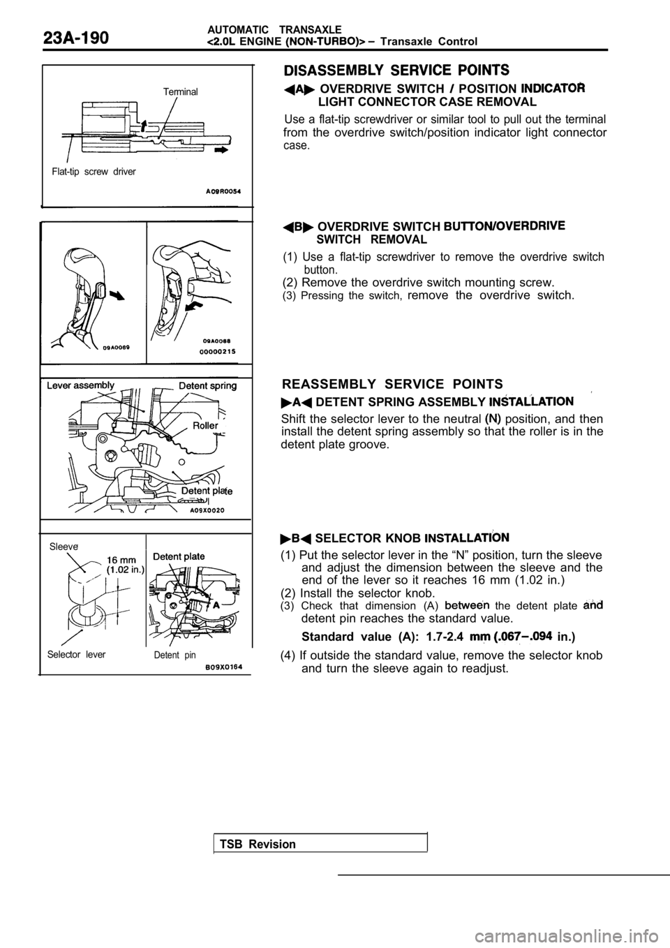
OVERDRIVE SWITCH POSITION
LIGHT CONNECTOR CASE REMOVAL
Use a flat-tip screwdriver or similar tool to pull out the terminal
from the overdrive switch/position indicator light connector
case.
OVERDRIVE SWITCH
SWITCH REMOVAL
(1) Use a flat-tip screwdriver to remove the overdr ive switch
button.
(2) Remove the overdrive switch mounting screw.
(3) Pressing the switch, remove the overdrive switch.
REASSEMBLY SERVICE POINTS
DETENT SPRING ASSEMBLY
Shift the selector lever to the neutral position, and then
install the detent spring assembly so that the roll er is in the
detent plate groove.
SELECTOR KNOB
(1) Put the selector lever in the “N” position, tur n the sleeve
and adjust the dimension between the sleeve and the end of the lever so it reaches 16 mm (1.02 in.)
(2) Install the selector knob.
(3) Check that dimension (A)
the detent plate
detent pin reaches the standard value.
Standard value (A): 1.7-2.4
in.)
(4) If outside the standard value, remove the selec tor knob
and turn the sleeve again to readjust.