Page 907 of 2103
MANUALTRANSAXLE OVERHAUL Transaxle
TRANSAXLE
DISASSEMBLY AND REASSEMBLY
33N m24
19 Nm14I
36
27Nm
Disassembly steps
1. Bolt 2. Rear cover
3. Reverse brake cone
41 Wave spring 5. Machine screw
6. Backup light switch
7.Gasket8.Poppetplug
9.Poppet spring10.Poppetball
11.Bolt
Lubricate all internaloil
12. Speedometer. driven gear assembly 13. Air breather 14. Spring
15. Lock nut 16. Lock nut17. speed synchronizer assembly
18.
speed shift fork .
19.Synchronizer ring
20. speed gear21.Needle bearing22. speed intermediate gear
TSB Revision
Page 951 of 2103
MANUAL TRANSAXLE OVERHAUL,
Center
Side
DISASSEMBLY SERVICE
ROLLER REMOVAL
Remove-the taper roller bearings ‘using the special
NOTE
(1) Do not reuse the bearing removed from shaft.
(2) Replace the inner and
races the taperroller
bearing as a set.
REASSEMBLY SERVICE POINTS
I N S T A L L A T I O N
(1) Install the spacer, side gear, pinion gear,
and
pinion shaft to the center differential
(2) Holding down the pinion shaft, select the of maxi-
mum thickness that allows the pinion gear to
and install it to the shaft.
(3) Install the side gear, spacer and output gear
the bolt to the specified torque.
(4) Select the spacer of maximum thickness that all ows the
side gear to turn lightly and install it.
Check that both side gears turn lightly.
Standard,
Center differential side gear end play:
mm in.) .
TAPER ROLLER BEARINGS INSTALLATION
TSB Revision
Page 959 of 2103
MANUAL TRANSAXLE OVERHAUL
R E A S S E M B L Y
B A C K L A S H A D J U S T M E N T ,
(1) a light and uniform coat
lead to the driven bevel gear teeth
brush.
using.
,
.
(2) install the spacer that has
., ,,
,
.
(3)Align the transfer drive bevel gear mating
, ,
(4) Align the transfer case adapter and drive bevel gear mating
marks.
(5) Assemble the transfer case and transfer case ad apter
and tighten to the specified torque.
(6) With the mating marks” aligned as in
that the transfer case and gear mating marks
are matched looking from the cover.’
Page 974 of 2103
MANUAL TRANSAXLE Specifications
SPECIFICATIONS
GENERAL SPECIFICATIONS
Model
Applicable engine
Gear ratio1
Reverse
Final gear ratio
Speedometer gear ratio (driven/drive)
SERVICE SPECIFICATIONS
Differential side gear end playmm (in.)
Differential case preload mm (in.)
Specifications
-1
floor shift floor shift
3.54
3.54
2.132.13
1.36 1.36
1 . 0 3
3.94 ,
3.55
Specifications,
. 0.18
TORQUE SPECIFICATIONS22210040017
ItemsN m
Back-up light switch 2418
Differential ring boltgear81
End cover bolt2921
Output bearing race retainingstrap9.6
R e v e r s e i d l e r b o l tgear2619
Reverse fork bracket bolt119.6
Shift cable bracket-transaxle28 20
Transaxle case clutch housing bolt2921
SEALANTS22210050010
ItemsSpecified sealant
End cover and bolts
Clutch housing to transaxle case
Loctite 18718 or equivalent
Loctite 51817 or equivalent
As required
As required
Clutch housing to transaxle case bolts Loctite 51817 or equivalent
As requiredI
TSB Revision
Page 997 of 2103

MANUAL TRANSAXLE Gear Case Overhaul
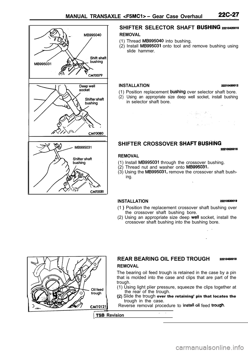
SHIFTER SELECTOR SHAFT
REMOVAL
(1) Thread into bushing.
(2) Install
onto tool and remove bushing using
slide hammer.
INSTALLATION
(1) Position replacement over selector shaft bore.
(2)Using an appropriate size deep well socket, install bushing
in selector shaft bore.
SHIFTER CROSSOVER
REMOVAL
(1) Install through the crossover bushing.
(2) Thread nut and washer onto
(3) Using the remove the crossover shaft bush-
ing.
INSTALLATION
(1 Position the replacement crossover shaft bushing o ver
the crossover shaft bushing bore.
(2) Using an appropriate size deep
socket, install the
crossover shaft bushing into the bushing bore.
.
REAR BEARING OIL FEED TROUGH
REMOVAL
The bearing oil feed trough is retained in the case by a pin
that is molded into the case and clips that are par t of the
trough.
(1) Using light plier pressure, squeeze the clips together at
the rear of the trough.
Slide the trough over the retaining’ pin that locates the
trough in the case.
Reverse removal procedure to
feed
Revision
Page 1009 of 2103

CONTENTS
AUTOMATIC TRANSAXLE
ENGINE (NON-TURBO)> . . . . . 115
AUTOMATIC TRANSAXLE KEY INTERLOCK
AND SHIFT LOCK MECHANISMS* . . . . . . . . 192
GENERAL INFORMATION
. . . . . . . . . . . . . . . . 115
LUBRICANTS. . . . . . . . . . . . . . . . . . . . . . . . . . . .117
ON-VEHICLE SERVICE . . . . . . . . . . . . . . . . . . . 159
Automatic Transaxle Control Component
Oil Temperature Sensor Continuity Check . . . . 160
Pinion Factor Writing Procedure After
TCM Replacement or Tire Size Change
. . . 159
Selector Level Operation Check . . . . . . . . . . . . . . ,166
Shift Lock Mechanism Check. . . . . . . . . . . . . . .
1 8 6
TCM Resetting Procedure . . . . . . . . . . . . .
..159
Torque Converter Stall Testing. . . . . . . . . . . . . .166
Transaxle Fluid Level Check . . . . . . . . . . .. . .159
Transaxle Fluid Replacement. . . . . . . . . . . . . . .
Transaxle Range Sensor Continuity . . .
Check. . . . . . . . . . . . . . . . . . . . . . . . . . . . . . . . . . . .163SERVICE SPECIFICATIONS.. . . .. . .Automatic Transaxle Control Component Layout
. . . . . . . . . . . . . . . . . . . . . . . . . . . . . . . . . . . . . . . . . . .
161SPECIAL TOOLS. . . . . . . . . . . . . . . . . . . . . . . . .117Clutch Air Pressure Tests . . . . . . . . . . . . . . . . . . .168
Fluid Leakage-Torque Converter Housing Area
Check. . . . . . . . . . . . . . . . . . . . . . . . . . . . . . . . . . . .169
Hydraulic Pressure Tests. . . . . . . . . . . . . . . . . . .169
Hydraulic Circuit. . . . . . . . . . . . . . . . . . . . . . . . . . .173
TRANSAXLE ASSEMBLY. . . . . . . . . . . . . . . .
TRANSAXLE CONTROL*. . . . . . . . . . . . . . . . .187
Selector Lever Assembly. . . . . . . . . . . . . . . . . . .189
Key Interlock Mechanism Check . . . . . . . . . . .
. 186CONTINUED ON NEXT PAGE
WARNINGS REGARDING SERVICING OF SUPPLEMENTAL EQUIPPED VEHICLES
WARNING! (1) Improper service or maintenance of any componen t of the
or any component, can lead to personal
injuryordeath inadvertent the inoperative).
(2) Service or maintenance of any component or SRS-related component must be perform ed only at an authorized
MITSUBISHI dealer.
(3)MITSUBISHI dealer personnel must thoroughly review this manual, and especially its GROUP Supplemental Re-
straint System (SRS) and GROUP 00 -Maintenance Serv ice before beginning any service or maintenance of any com-
ponent of the
or any component.
NOTEThe SRS includes the following components: SRS-ECU, SRS warning light, air bag module, clockspring and inte rconnecting wiring.Other SRS-related components (that may have to be removed/installed in connection with SRS service or maintenance) are indi-cated in the table of contents by an asterisk
Page 1020 of 2103

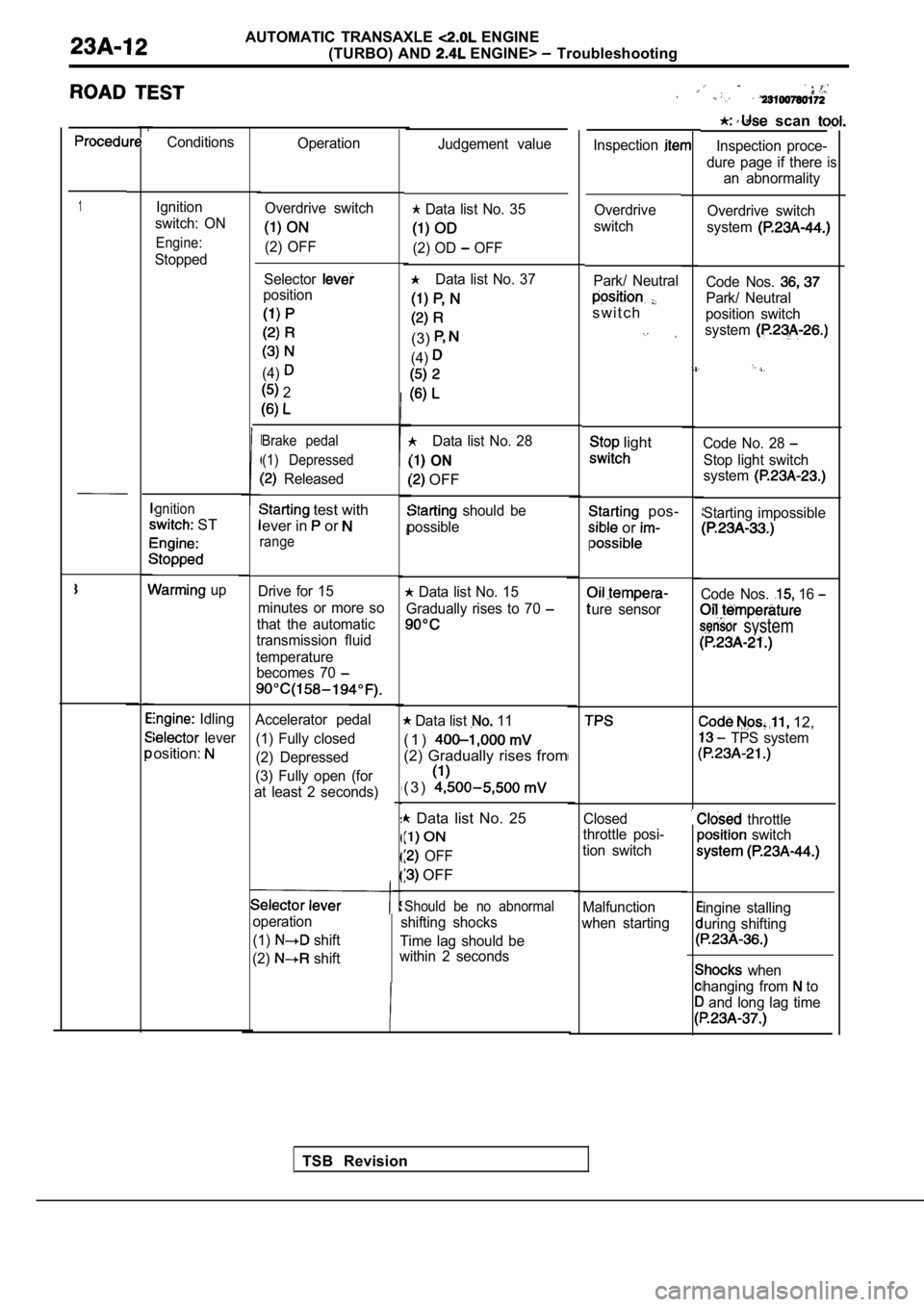
AUTOMATIC TRANSAXLE ENGINE
(TURBO) AND
ENGINE> Troubleshooting
scan
Inspection proce-
dure page if there an abnormality
is
Conditions Operation
Inspection
1Ignition
switch: ON
Engine:
Stopped
gnition
ST
up
Idling
lever
osition:
Judgement value
Overdrive switch
system
Code Nos.
Park/ Neutral
position switch
system
Code No. 28
Stop light switch
system
Starting impossible
Code Nos. 16
system
12,
TPS system
throttle switch
ingine stalling
uring shifting
when
hanging from
to
and long lag time
Overdrive switch
(2) OFF
Data list No. 35
(2) OD OFF
Data list No. 37
(3)
(4)
Data list No. 28
ON
OFF
should be
possible Overdrive
switch
Selector
position
(4)
2
Park/ Neutral
s w i t c h
Brake pedal (1) Depressed
Released
light
pos-
or
I
ure sensor
test with
ever in
or
range
Drive for 15
minutes or more so
that the automatic
transmission fluid
temperature becomes 70 Data list No. 15
Gradually rises to 70
Accelerator pedal
(1) Fully closed
(2) Depressed
(3) Fully open (for
at least 2 seconds) Data list 11
( 1 )
(2) Gradually rises from
( 3 )
Data list No. 25
OFF
OFF
Closed
throttle posi-
tion switch
Should be no abnormal
shifting shocks
Time lag should be
within 2 seconds Malfunction
when starting
operation
(1)
shift
(2)
shift
TSB Revision
Page 1027 of 2103

AUTOMATIC TRANSAXLE ENGINE
(TURBO) AND
ENGINE> Troubleshooting
INSPECTION CHART FOR DIAGNOSTIC TROUBLE CODES
CodeDiagnostic item Reference page
11Throttle position sensor system Excessive
output
12Throttle position sensor systemoutput
13Throttle position sensor system Defective
sensor
14Throttle position sensor system Defective
sensor
adjustment
15
16
21
22
23
Oil temperature sensor system
Oil temperature sensor system
servo switch system
servo switch system
Ignition signal system Open circuit
Short circuit
Open circuit
Short circuit
Open circuit
22
22
22
28
31
32
36
Stop light switch system
Pulse generator A (PG-A) system
Pulse generator
(PG-B) system
Park/Neutral position switch svstem Short circuit
Open circuit
Open circuit Short circuit
23
24
25
26
Torque
converter
37
41
42
43
Park/Neutral position switch system
Shift control solenoid valve A (SCSV-A) system
Shift control solenoid valve A (SCSV-A) system
Shift control solenoid valve
(SCSV-B) system Open circuit
Open circuit
Short circuit
Open circuit
26
27
27
27
Revision