1990 MITSUBISHI SPYDER air bleeding
[x] Cancel search: air bleedingPage 1678 of 2103
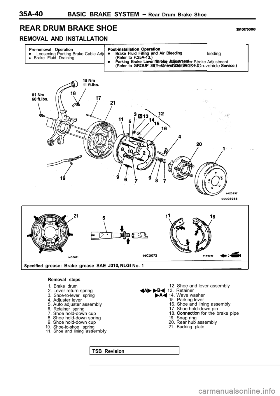
BASIC BRAKE SYSTEM Rear Drum Brake Shoe
REAR DRUM BRAKE SHOE
REMOVAL AND INSTALLATION
Pre-removal OperationLoosening Parking Brake Cable Adjusting Nut. lBrake Fluid Filling and Air Bleedingl
Brake Fluid Drainingl
Parking Brake Lever Stroke Adjustment
(Refer to GROUP 36 On-vehicle
2116
Specified grease: Brake grease SAE No. 1
Removal steps
1.Brake drum2. Lever return spring3.Shoe-to-lever spring4.Adjuster lever
5. Auto adjuster assembly
6.Retainer spring7. Shoe hold-down cup
8. Shoe hold-down spring
9. Shoe hold-down cup
10.Shoe-to-shoe spring11. Shoe and lining assembly 12. Shoe and lever assembly
13. Retainer
14. Wave washer15.Parking lever
16. Shoe and lining assembly
17. Shoe hold-down pin
18.
for the brake pipe19.Snap ring
20. Rear hub assembly
21.Backing plate
TSB Revision
Page 1724 of 2103
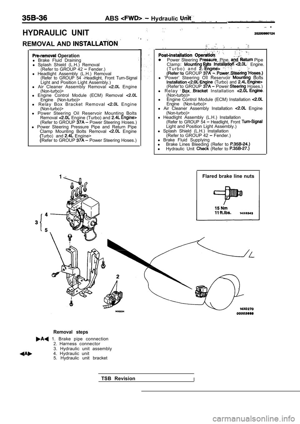
HYDRAULIC UNIT
ABS Hydraulic .
.
REMOVAL AND
.
Operationl Brake Fluid Draining
l Splash Shield (L.H.) Removal
(Refer to GROUP 42
Fender.)
l Headlight Assembly (L.H.) Removal
(Refer to GROUP 54 -Headlight, Front Turn-SignalLight and Position Light Assembly.)
l Air Cleaner Assembly Removal Engine(Non-turbo)>l Engine Control Module (ECM) Removal Engine (Non-turbo)>l R e l a y B o x B r a c k e t R e m o v a l E n g i n e(Non-turbo)>
Power Steering Pipe, Pipe
Clamp: Engine.( T u r b o ) a n d . GROUP l ‘Power‘ Steering Oil Reservoir Bolts (Turbo) and (Refer’to GROUP Power Hoses.)
l R e l a y Installation (Non-turbo)>l Engine Control Module (ECM) Installation Engine (Non-turbo)>l Air Cleaner Assembly Installation Engine(Non-turbo)>l Power Steering Oil Reservoir Mounting Bolts
Removal Engine (Turbo) and (Refer to GROUP Power Steering Hoses.)
l Power Steering Pressure Pipe and Return Pipe
Clamp Mounting Bolts Removal
EngineTurbo)and Engine>
Refer to GROUP Power Steering Hoses.) l
Headlight Assembly (L.H.) Installation
(Refer to GROUP 54 Headlight, Front Light and Position Light Assembly.)
l Splash Shield (L.H.) Installation
(Refer to GROUP 42
Fender.)
l Brake Fluid Supplying
l Brake Lines Bleeding (Refer to
lHydraulic Unit (Refer to
Flared brake line nuts
Removal steps
1. Brake pipe connection2.Harness connector
3. Hydraulic unit assembly
4. Hydraulic unit 5. Hydraulic unit bracket
TSB Revision
I
Page 1775 of 2103
CONTENTS
GENERAL INFORMATION. . . . . . . . . . . . . . . . . . 2POWER STEERING GEAR . . . . . . . . . . 18
LUBRICANTS. . . . . . . . . . . . . . . . . . . . . . . . . . . . . .
3P O W E R S T E E R I N G H O S E ’ S
Engine . . . . .
ON-VEHICLE SERVICE . . . . . . . . . . . . . . . . . . . . . 7 Engine (Turbo) and . . . 47
Bleeding. . . . . . . . . . . . . . . . . . . . . . . . . . . . . . . . . . . .9
Checking Steering Wheel Return to Center
. . . .8
Fluid Level Check. . . . . . . . . . . . . . . . . . . . . . . . . . .8
Fluid Replacement. . . . . . . . . . . . . . . . . . . . . . . . . . .9
Oil Pump Test
. . . . . . . . . . . . . . . . . . . . .
Power Steering Pressure Switch Check
. . . . . . .13
Stationary Steering Effort Check. . . . . . . . . . . . . .8
Steering Angle Check. . . . . . . . . . . . . . . . . . . . . . . .7
Steering Wheel Free Play Check. . . . . . . . . . . . . . .7
Tie Rod End Ball Joint Breakaway Torque Check
. . . . . . . . . . . . . . . . . . . . . . . . . . . . . . . . . . . . . . . . . . . . .
7
POWER STEERING OIL PUMP
Engine (Non-turbo)> . . . . . . . . . . . . . . .
Engine (Turbo) and Engine> . . . 39
SEALANTS. . . . . . . . . . . . . . . . . . . . . . . . . . . . . . . .4
SERVICE SPECIFICATIONS . . . . . . . . . . . . . . . . . 3
SPECIAL TOOLS. . . . . . . . . . . . . . . . . . . . . . . . . . .4
STEERING WHEEL AND
. . . . . . . . . . 14
WARNINGS REGARDING SERVICING OF SUPPLEMENTAL (SRS) EQUIPPED
WARNING!(1)Improper service or maintenance of any component of the SRS, or any SRS-related component, can lead
the SRS inoperative).(2) Service or maintenance of any SRS component or component must be performed MITSUBISHI dealer.(3) MITSUBISHI dealer personnel must this and especially its GROUP straint System (SRS) and GROUP 00 -Maintenance beginning any service or maintenance of any com-
ponent of the SRS or any
NOTEThe includes the following components: SRS light, air bag module, and interconnecting wiring.Other SRS-related components (that may have to be r emoved/installed in with service or maintenance) are indi-
cated in the table of contents by an asterisk
Page 1783 of 2103
STEERING On-vehicle
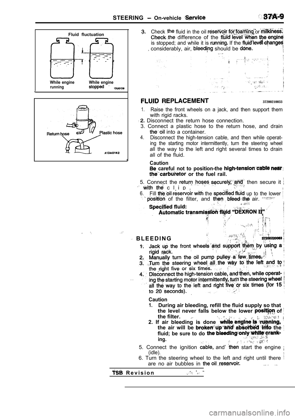
Fluid fluctuation
While enginerunningWhile engine
Check fluid in the oil or
difference of the
is stopped; and while it is If the
considerably, air, should be
37200210033
1.Raise the front wheels on a jack, and then support them
with rigid racks.
Disconnect the return hose connection.
3. Connect a plastic hose to the return hose, and d rain
into a container.
4.Disconnect the high-tension cable, and then while operat-
ing the starting motor intermittently, turn the steering wheel
all the way to the left and right several times to drain
all of the fluid.
Caution
careful not to position-the
or the fuel rail.
5. Connect the then secure it
c l i p .
6.Fill the up to the lower
of the filter, and air.
B L E E D I N G
. .
Caution
1.During air bleeding, refill the fluid supply so tha t
the level never falls below the lower
of
the filter.
2. If air bleeding is done
the air will be the
fluid; be sure to do
ing.
5. Connect the ignition and’ start the engine
(idle).
6. Turn the steering wheel to the left and right un til there
are no air bubbles in
R e v i s i o n.
Page 1784 of 2103
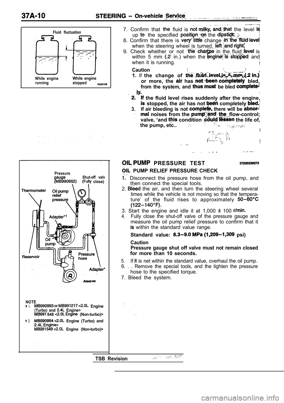
Fluid fluctuation
While engineWhile enginerunning stopped
PressureShut-off valv close)
NOTE
l l: Engine(Turbo) and Engine> 848 (Non-turbo)>
l 2: Engine (Turbo) and
Engine (Non-turbo)>
7. Confirm that fluid is the level
up the specified the
8. Confirm that there is change
when the steering wheel is turned,
9. Check whether or not in the fluid is
within 5 mm
in.) when the and
when it is running.
Caution
1. Ifthe change of
or more, the has bled,
from the system, and be bled ,
the fluid level rises suddenly after the engine,
stopped, the air has not completely
3.If air bleeding is not there will be
noises from the flow-control;
valve, ‘and
condition the life of,
the pump, etc.. ,
. . .
PRESSURE TEST
PUMP RELIEF PRESSURE CHECK
Disconnect the pressure hose from the oil pump, an d
then connect the special tools.
2.
the air, and then turn the steering wheel several
times while the vehicle is not moving so that the t empera-
ture’ of the fluid rises to approximately
3. Start the engine and idle it at 1,000 100
4.Fully close the shut-off valve of the pressure gaug e and
measure the oil pump relief pressure to confirm tha t it
within the standard value range.
Standard value:
psi)
Caution Pressure gauge shut off valve must not remain close d
for more than 10 seconds.
5.If is net within the standard value, overhaul the oil pump.
6. . . Remove the special tools, and the tighten th e pressure
hose to the specified torque.
7. Bleed the system.
TSB Revision
Page 1821 of 2103
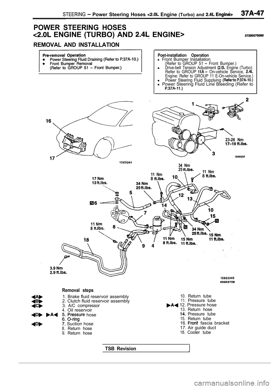
STEERING Power Steering Hoses Engine (Turbo) and
POWER STEERING HOSES
ENGINE (TURBO) AND ENGINE>
REMOVAL AND INSTALLATION
Post-installation Operationl Front Bumper Installation(Refer to GROUP 51 Front Bumper.)lDrive-belt Tension Adjustment Engine (Turbo):Refer to GROUP On-vehicle Service, Engine: Refer to GROUP 11 E-On-vehicle Service.)lPower Steering Fluid Supplying l Power Steering Fluid Line Bleeding (Refer to
23-26 Nm
34 Nm
25
11 Nm 11 Nm88
118
Removal steps
1. Brake fluid reservoir assembly
2. Clutch fluid reservoir assembly
3. A/C compressor4.Oil reservoir
hose
Suction hose
8.Return hose
9.Return hose
10.Return tube11.Pressure tube 12. Pressure hose13.Return hosePressure tube
15.Return tube16. fascia bracket
17. Air guide duct
18.Cooler tube
TSB Revision
Page 2093 of 2103

ALPHABETICAL
A
ABS OPERATIONCheck. . . . . . . . . . . . . . . . . . . . . . . . . . . . . . . . . . .
. . . . . . . . . . . . . . . . . . . . . . . . . . . . . . . . . . .
ABS-ECU. . . . . . . . . . . . . . . . . . . . . . . . . . . . . . . . . . . . . . . . .
. . . . . . . . . . . . . . . . . . . . . . . . . . . . . . . . . . . . . . . . .
ACCELERATOR CABLE. . . . . . . . . . . . . . . . . . . . . . . . . . . . . . . .Adjustment. . . . . . . . . . . . . . . . . . . . . . . . . . . . . . . . . . . . . . . . .
Check. . . . . . . . . . . . . . . . . . . . . . . . . . . . . . . . . . . . . . . . . . . . .ACCELERATOR PEDAL. . . . . . . . . . . . . . . . . . . . . . . . . . . . . . . .
ADAPTER, Transfer Case . . . . . . . . . . . . . . . . . .
AERO PARTS. . . . . . . . . . . . . . . . . . . . . . . . . . . . . . . . . . . . . . . .
AIR BAG CONTROL UNIT (SRS-ECU), SRS. . . . . . . . . . .AIR BAG MODULES. . . . . . . . . . . . . . . . . . . . . . . . . . . . . . . . .
Deployed Disposal Procedures. . . . . . . . . . . . . . . . . . . . .
Disposal Procedures. . . . . . . . . . . . . . . . . . . . . . . . . . . . .
Disposal. . . . . . . . . . . . . . . . . . . . . . . . . . . . .
AIR CLEANER ELEMENT, Maintenance. . . . . . . . . . . . . . . . . .AIR CONDITIONING SWITCH
ENGINE (NON-TURBO)>. . . . . . . . . . . . . . ENGINE (TURBO) AND .AIR COOLER, charge. . . . . . . . . . . . . . . . . . . . . . . . . . . . . . . . . . .
AIR FILTER. . . . . . . . . . . . . . . . . . . . . . . . . . . . . . . . . . . . . . . . . .
ALIGNMENT
Front Wheel, Check and Adjustment. . . . . . . . . . . . . . . . .
Wheel, Rear, Check and Adjustment. . . . . . . . . . . . . . . . . . .AMPLIFIER. . . . . . . . . . . . . . . . . . . . . . . . . . . . . . . . . . . . . . . . . .
GEAR AND TRANSFER DRIVE GEAR SET
. . . . . . . . . . . . . . . . . . . . . . . . . . . . . . . .
. . . . . . . . . . . . . . . . . . . . . . . . . . . . . . . . . . . . . . . .
ANTENNA.
ARM Compression, Lower
. . . . . . . . . . . . . . . . . . . . . . . . . . . . . . .Lateral, Lower. . . . . . . . . . . . . . . . . . . . . . . . . . . . . . . . . . .
Lower. . . . . . . . . . . . . . . . . . . . . . . . . . . . . . . . . . . . . . . . . . . . .
Toe Control. . . . . . . . . . . . . . . . . . . . . . . . . . . . . . . . . . . . . . . .
Trailing. . . . . . . . . . . . . . . . . . . . . . . . . . . . . . . . . . . . . . . . . . . .
Upper
Suspension>. . . . . . . . . . . . . . . . . . . . . . . . . . .ARMS, Rocker . . . . . . . . . . . . . . . . . . . . . . . . . . .11AUTO-CRUISE CONTROL. . . . . . . . . . . . . . . . . . . . . . . . . . . . .
AUTO-CRUISE CONTROL CABLE, Check andAdjustment. . . . . . . . . . . . . . . . . . . . . . . . . . . . . . . . . . . . . . . . . . .
AUTO-CRUISE CONTROL COMPONENT, Check. . . . . . . . .AUTO-CRUISE CONTROL SYSTEM, Operation Check. . . .AUTOMATIC TRANSAXLE FLUID, Maintenance. . . . . . . . . .AUTOMATIC TRANSAXLE CONTROL COMPONENTCheck
ENGINE (NON-TURBO)>.. . . . . . . . . . . .Layout ENGINE (NON-TURBO)>. . . . . . . . . . . .AUTOMATIC TRANSAXLE KEY INTERLOCK AND SHIFT LOCKMECHANISMS
ENGINE (NON-TURBO)>. . . . . . . . . . . . . . . . . . .
ENGINE (TURBO) AND ENGINE>.. . . . . . .AXLE
Rear, Total Backlash Check. . . . . . . . . . . . . . . . . . . . . . . . . .
AXLE OIL
Rear, Maintenance
. . . . . . . . . . . . . . . . . . . . . . . . . . . . . . . . .
BACK-UP LIGHT. . . . . . . . . . . . . . . . . . . . . . . . . . . . . . . . . . . . .BALL JOINT, Tie Rod End, Breakaway Torque Check. . . . .BALL JOINT SEALS, Maintenance. . . . . . . . . . . . . . . . . . . . . .
BARStabilizer Suspension>. . . . . . . . . . . . . . . . . . . . .
Suspension>. . . . . . . . . . . . . . . . . . . . . . . .
BASIC IDLE SPEED, Adjustment ENGINE (TURBO)
AND ENGINE>. . . . . . . . . . . . . . . . . . . . . . . . . . . . . . . .
BATTERY
Charging
. . . . . . . . . . . . . . . . . . . . . . . . . . . . . . . . . . . . . . . . . .
Check. . . . . . . . . . . . . . . . . . . . . . . . . . . . . . . . . . . . . . . . . . ..Testing Procedure. . . . . . . . . . . . . . . . . . . . . . . . . . . . .. . .
BELT
Compressor, Adjustment. . . . . . . . . . . . . . . . . . . . . . . . .
(For Generator), Maintenance. . . . . . . . . . . .. . . . . (For Power steering pump), Maintenance. . . . . . . . . (For Water pump), Maintenance. . . . . . . . .. .. . .Timing. . . . . . . . . . . . . . . . . . . .
. . . . . . . . . . . . . . . . . . . . . . . . . . .
Timing. . . . . . . . . . . . . . . . . . . . . . . . . . . . .
. . . . . . . . . . . . . . . . . . . . . ... . . . . . . . .
. . . .Timing, Maintenance. . . . . . . . . . . . . . . . . . . . . . . . . . . . . . . .
BLEEDING
ABS. . . . . . . . . . . . . . . . . . . . . . . . . . . . . . . . . . . . . . . . . . . .
Basic Brakes. . . . . . . . . . . . . . . . . . . . . . . . . . . . . . . . . . . .
Clutch. . . . . . . . . . . . . . . . . . . . . . . . . . . . . . . . . . .. . . . . . .. . . . . . . . . . . . . . . . . . . . . . . . . . . . . . . . . . . . . . . . . .
BLOWER. . . . . . . . . . . . . . . . . . . . . . . . . . . . . . . . . . . . . . . . . . . .
BOLTHub, Replacement . . . . . . . . . . . . . . . . . . .. . . . .
. . . . . . . . . . . . . . . . . . . . . .
. . . . . . . . . . . . . . . . . . . . . . 2 7 4 1
BOOSTER
Brake. . . . . . . . . . . . . . . . . . . . . . . . . . . . . . . . . . . .
. . . . . . . . . . . . . . . . . . . . . . . . . . . . .
Brake, Operating Test. . . . . . . . . . . . . . . . . . . . . . . . . . . . . O-IBOOTS, Shaft, Maintenance. . . . . . . . . . . . . . . . . . . . . . .
BRACKET. . . . . . . . . . . . . . . . . . . . . . . . . . . . . .
BRAKE
. . . . . . . . . . . . . . . . . . . . . . . . . . . . . . . . . . . . . .
Disc, Rear. . . . . . . . . . . . . . . . . . . . . . . . . . . . . . . . . . . . . . .
Low-reverse. . . . . . . . . .. . . . . . . .. . . . . . . . . . . . . . . . . . . . . . . . . . . .
BRAKE BOOSTER
. . . . . . . . . . . . . . . . . . . . . . . . . . . . . . . . . . . . . . . . . .
Test. . . . . . . . . . . . . . . . . . . . . . . . . . . . . . . . . . . .
BRAKE DISC
Front, Run-out Check. . . . . . . . . . . . . . . . . . . . . . . . . .. Run-out Correction. . . . . . . . . . . . . . . . . . . . . . . . . .
Front, Thickness Check. . . . . . . . . . . . . . . . . . . . . . . . . . .
Rear, Run-out Check.. . . . . . . . . . . . . . . . . . . . . . . . . . . . .
Rear, Run-out Correction. . . . . . . . . . . . . . . . . . . . . . . . . .
Rear, Thickness Check. . . . . . . . . . . . . . . . . . . . . . . . . . . .
BRAKE DRUM
Inside Diameter Check with Rear Drum . . . . . . . . . . . . . . . . . . . . . . . . . . . . . . . . . . . . . . . . . . . . . . . . .
BRAKE FLUID LEVEL SENSOR, Check. . . . . . . . . . . . . . . .
BRAKE HOSES, Maintenance. . . . . . . . . . . . . . . . . . . . . . . . . .
BRAKE LINING
Thickness. . . . . . . . . . . . . . . . . . . . . . . . . . . . . . . . . .
BRAKE PAD
Disc, Front, Check and Replacement
. . . . . . . . . . . . . . . .Disc, Rear, Check and Replacement. . . . . . . . . . . . . . . .
BRAKE PEDAL. . . . . . . . . . . . . . . . . . . . . . . . . . . . . . . . . . . . .
Check and Adjustment. . . . . . . . . . . . . . . . . . . .. . . . . . .BRAKE ROTOR, Disc, Front, Check. . . . . . . . . . . . . . . . .BREAKAWAY TORQUE, Rod End Ball Joint, . . .BUMPERFront. . . . . . . . . . . . . . . . . . . . . . . . . . . . . . . . . . . . . . . . . . . . . . .Rear. . . . . . . . . . . . . . . . . . . . . . . . . . . . . . . . . . . . . . . ......