Page 1540 of 2103
REAR AXLE Rear Hub
REMOVAL SERVICE
CALIPER ASSEMBLY ,
Remove the caliper assembly it.
Socket
ABS ROTOR
TSBRevision
INSTALLATION SERVICE POINT
ROTOR INSTALLATION
INSPECTION
lCheck the oil seal for crack or damage.
lCheck the ABS rotor for chipped teeth.
27100210105
Page 1541 of 2103
REAR AXLE Knuckle
REMOVAL AND INSTALLATION
27100300055
Pre-removal and Post-installation OperationlRear Wheel Speed sensor Removal and Installation
85-99
71‘2
Removal steps
1. Trailing arm connection
2. Lower arm connection
3. Toe control arm ball joint and
knuckle connection
4. Shock absorber connection
5. Upper arm connection
6. Knuckle
Caution
7. Hub cap without
l : Indicates parts which should be temporarily
and then fully tightened with the vehicle
on the ground in the unladen condition.
TSB Revision
Page 1554 of 2103
REAR AXLE Knuckle
REMOVAL AND INSTALLATION
II and Post-installation OperationlRear Wheel Speed Sensor Removal and Installation with lRear Hub Assembly Removal and installation(Refer to
98, 71
98
118-13785-99
TSB Revision
9871
Removal steps
1. Trailing arm connection
2. Lower arm connection
3. Toe control arm ball joint and knuckle connection (Refer to
4. Shock absorber connection
5. Upper arm connection
6. Knuckle
CautionIndicates
and thenarts which should be tightened, tightened the veh on the groundin the unladen condition.
Page 1555 of 2103
REAR AXLE Drive
2 7 1 0 0 3 3 0 0 2 3
REMOVAL AND INSTALLATION
Brake Line Bleeding with drum brakes>
(Refer to GROUP 36
On-vehicle Service.)
9871
I I10
,19
44118-1373385-99
11
with drum brakes>
11
9871. .,
Removal steps
1. Rear wheel speed sensor
2. Caliper assembly (Refer to 3. Brake disc
4. Brake drum
5. Shoe and lining assembly (Refer to
GROUP 36
Parking Brake.)6. Shoe and lever assembly
7. Clip8. Parking brake cable
9. Brake pipe connection
10. Shock absorber connection Trailing arm connection12. Lower arm connection
13. Toe control armball joint andknuckle connection(Refer to 14. pin 15. Drive shaft nut16. Washer
17. Differential mount support
18. Drive shaft
19.
Caution1.For vehicles with ABS, careful not to damagedrive shaft rotor.2.l : Indicates parts should be temporarily and then fully tightened the on the
ground in the unladen condition.
TSB Revision
Page 1563 of 2103

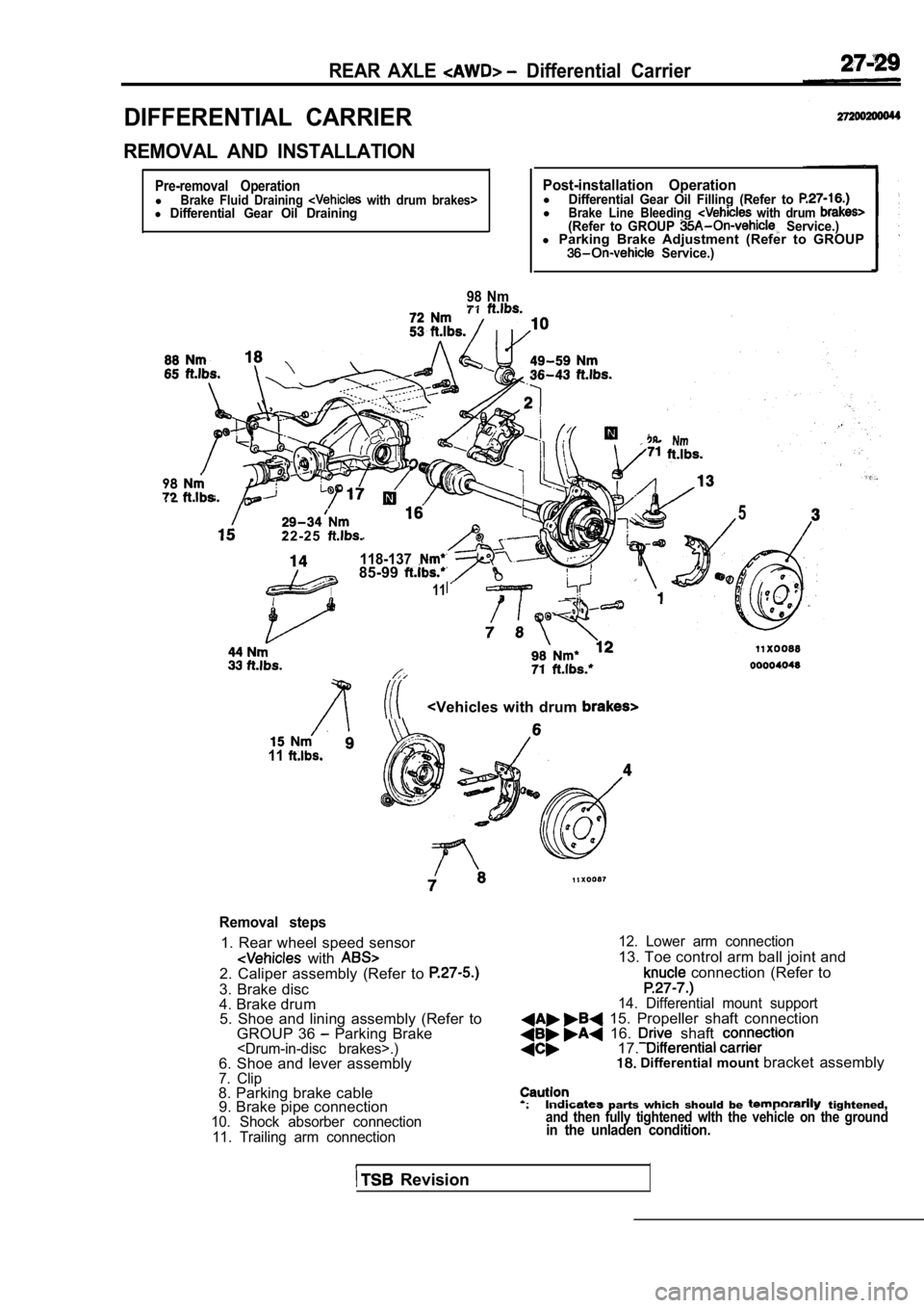
REAR AXLE Differential Carrier
DIFFERENTIAL CARRIER
REMOVAL AND INSTALLATION
Pre-removal OperationlBrake Fluid Draining with drum brakes>l Differential Gear Oil Draining
98 Nm
Post-installation OperationlDifferential Gear Oil Filling (Refer to lBrake Line Bleeding with drum (Refer to GROUP Service.)l Parking Brake Adjustment (Refer to GROUP Service.)
98
2 2 - 2 5
118-13785-99
11
5
11
Removal steps
1. Rear wheel speed sensor
with 2. Caliper assembly (Refer to
3. Brake disc
4. Brake drum
5. Shoe and lining assembly (Refer to
GROUP 36
Parking Brake.)6. Shoe and lever assembly7. Clip8. Parking brake cable9. Brake pipe connection
10. Shock absorber connection
11. Trailing arm connection 12. Lower arm connection
13. Toe control arm ball joint and
connection (Refer to
14. Differential mount support 15. Propeller shaft connection 16. shaft 17. Differential mount
bracket assembly
parts which should be tightened,and then fully tightened wlth the vehicle on the gr oundin the unladen condition.
Revision
Page 1599 of 2103

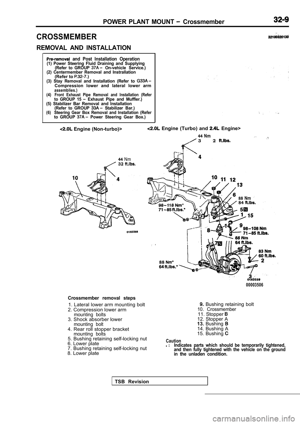
POWER PLANT MOUNT Crossmember
CROSSMEMBER
REMOVAL AND INSTALLATION
and Post Installation Operation(1) Power Steering Fluid Draining and Supplying(Refer to GROUP On-vehicle Service.)
(2) Centermember Removal and Instrallation
(Refer to (3) Stay Removal and Installation (Refer to Compression lower and lateral lower armassemblies.)(4)Front Exhaust Pipe Removal and Installation (Referto GROUP 15 Exhaust Pipe and Muffler.)
(5) Stabilizer Bar Removal and Installation (Refer to GROUP
Stabilizer Bar.)(6)Steering Gear Box Removal and Installation (Referto GROUP Power Steering Gear Box.)
Engine (Non-turbo)>
44Nm32
Engine (Turbo) and Engine>
44Nm3 2
88Nm84
88
00003506
Crossmember removal steps
1. Lateral lower arm mounting bolt
2. Compression lower arm
mounting bolts3. Shock absorber lowermounting bolt4. Rear roll stopper bracketmounting bolts5. Bushing retaining self-locking nut
6. Lower plate
7. Bushing retaining self-locking nut
8. Lower plate
Bushing retaining bolt10. Crossmember11. Stopper 12. Stopper A
13. Bushing
14. Bushing A
15. Bushing
Cautionl Indicates parts which should be temporarily tighten ed,
and then fully tightened with the vehicle on the gr ound
in the unladen condition.
TSB Revision
Page 1601 of 2103
FRONT
CONTENTS
COMPRESSION LOWER ARM ANDSHOCK ABSORBER ASSEMBLY.. . . . . . . . 8
LATERAL LOWER ARM ASSEMBLIES . . . . . 11
SPECIAL TOOLS3
GENERAL INFORMATION. . . . . . . . . . . . . . . . . .2
STABILIZER BAR. . . . . . . . . . . . . . . ..*.......14
ON-VEHICLE SERVICE . . . . . . . . . . . . . . . . . . . . . 4
Front Wheel Alignment CheckTROUBLESHOOTING . . . . . . . . . . . . . . . . . . . . 4
and Adjustment . . . . . . . . . . . . . . . . . . . . . . . . . . . . . .4UPPER ARM ASSEMBLY . . . . . . . . . . . . . . . .
. . . 6
SERVICE SPECIFICATIONS . . . . . . . . . . . . . . . . . 3
Page 1602 of 2103

FRONT SUSPENSION General Information
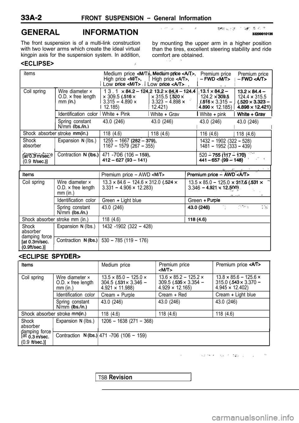
GENERAL INFORMATION
The front suspension is of a multi-link constructionby mounting the upper arm in a higher position
with two lower arms which create the ideal virtual than the tires, excellent steering stability and ride
kingpin axis for the suspension system. In addition ,comfort are obtained.
itemsMedium price
High price
Premium price
I
Premium priceHigh price I Low Low ,I
Coil spring
Wire diameter
O.D. free length
1 3 . 1
309.5 315.5 mm3.315 4.890 3.323 4.898
124.2
3.315
I 12.185) 12.421) 12.185)
Identification color White Pink White GravIWhite pink
124.4 315.5
Spring constant 43.0 (246) 43.0 (246)
I
43.0 (246)N/mmI
43.0 (246)
I
Shock absorberstroke118 (4.6) 118(4.6)116 (4.6) 118 (4.6)
Shock Expansion
(Ibs.)1255 16671432 1902(322 528)
absorber 1167 1579(267355)1481 1952 (333 439)
damping force
Contraction471-706(106520
(0.9
Premium price AWD
Coilspring Wire diameter 13.3 84.6 124.6 312.013.5 85.0 125.0
O.D. free length 3.331 4.906 12.283)3.346
mm (in.)
Identification color Green Light blueGreen
Spring constant43.0 (246)
N/mm
Shock absorber stroke mm (in.)118 (4.6)
ShockExpansion (Ibs.)
1432 -1902 (322 428)
absorber
damping force
Contraction530 785 (119 176)
TSBRevision
Medium price Premium pricePremium price
Coil spring Wire diameter 13.5 85.0 125.0 13.6 85.2 125.2 13.8 85.6 125.6
O.D. free length304.5 3.346 309.5 3.354 315.0 3.370
mm (in.) 4.921 11.988)
4.929 12.165)4.945 12.402)
Identification color Cream
PurpleCream RedCream Light blue
Spring constant 43.0 (246) 43.0 (246) 43.0 (246)
N/mm
Shock absorber stroke 118 (4.6) 118 (4.6) 118 (4.6)
ShockExpansion (Ibs.)
1206 1638 (271 368)
absorber
damping force
[atContraction 471 -706 (106 159)
(0.9