Page 772 of 2103

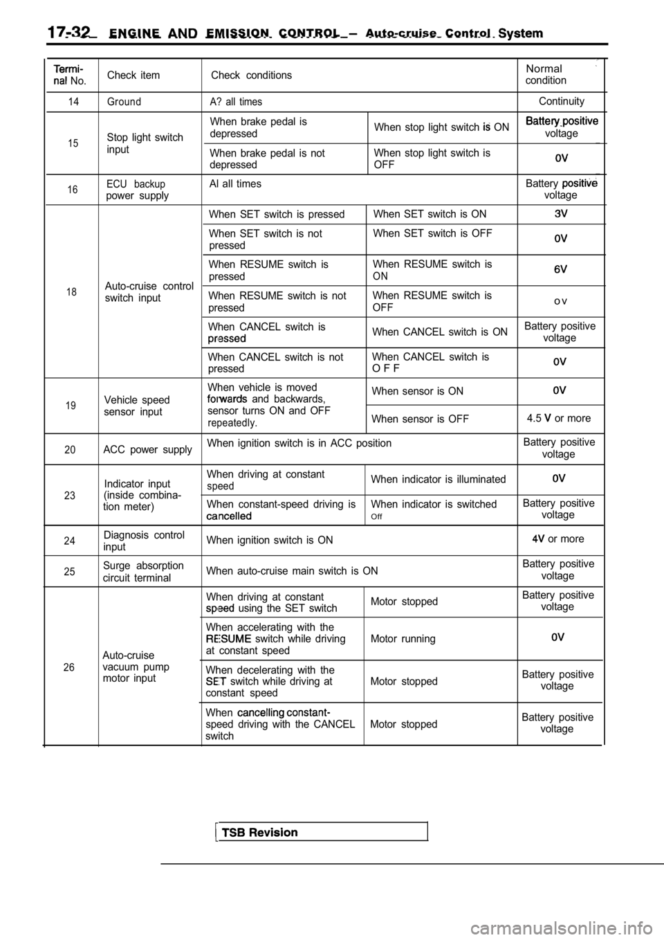
E N G I N E EMISSION CONTROL Auto-cruise Control
No.
14
15
Check item
Ground
Stop light switch
inputCheck conditions
A? all times
When brake pedal is
depressed
When brake pedal is not
depressed
Normal
condition
Continuity
When stop light switch ON voltage
When stop light switch is
OFF
16
18
19ECU backupAl all times Battery
power supply voltage
When SET switch is pressed When SET switch is ON
When SET switch is notWhen SET switch is OFF
pressed
When RESUME switch is When RESUME switch is
pressed
ONAuto-cruise control
switch input When RESUME switch is not
When RESUME switch is
pressed OFF
o v
When CANCEL switch is
When CANCEL switch is ONBattery positivevoltage
When CANCEL switch is not When CANCEL switch is
pressed
O F F
When vehicle is moved When sensor is ON
Vehicle speed and backwards,
sensor input sensor turns ON and OFF
repeatedly.When sensor is OFF
4.5 or more
20ACC power supplyWhen ignition switch is in ACC position
Battery positive
voltage
23
24
Indicator input
(inside combina-
tion meter)
Diagnosis control
input When driving at constantspeedWhen indicator is illuminated
When constant-speed driving is When indicator is swi
tchedBattery positive
Offvoltage
When ignition switch is ON
or more
25
26Surge absorption
circuit terminal
Auto-cruise
vacuum pump motor input When auto-cruise main switch is ON
When driving at constant
Motor stopped
using the SET switch
When accelerating with the
switch while driving Motor running
at constant speed
When decelerating with the
switch while driving at Motor stopped
constant speed
When
speed driving with the CANCEL Motor stopped
switch Battery positive
voltage
Battery positive voltage
Battery positivevoltage
Battery positive voltage
Page 808 of 2103
17-68ENGINEAND EMISSION CONTROL (Turbo) and
EVAPORATIVE EMISSION CONTROL, SYSTEM
GENERAL INFORMATION Engine (Turbo)>
The evaporative emission control system preventsWhen driving with a low to medium load on the
fuel vapors generated in the fuel tank from escapin gengine, the fuel vapor absorbed by the EVAP
into the atmosphere.ter is drawn into the port of the throttle body.
Fuel vapors from the fuel tank flow through the When driving with a high load on the engine, the
fuel tank pressure control valve and vapor pipe/hos
epurge control valve opens and the fuel vapor
to be stored temporarily in the canister.sorbed by the EVAP canister is drawn into the air
intake hose.
SYSTEM DIAGRAM
Check valve EVAP canister
To air
hoseintake
EVAP purge s o l e n o i d
Revision
Engine control
module
I1
Barometric pressure sensor
Intake air temperature sensor
Engine coolant temperature sensor
Volume air flow sensor
COMPONENT LOCATION
Evaporative emission purge solenoid
Page 1171 of 2103
AUTOMATIC TRANSAXLE
ENGINE (NON-TURBO)>: On-vehicle _ _
AUTOMATIC
COMPONENT CHECK
SPEED SENSOR
(1) Disconnect the input speed sensor connector.
(2) Measure the resistance
the input speed
side connector terminals 1 and 2.
Standard value:,
(3) If the resistance is outside the standard value , replace
the input speed sensor.
OUTPUT SPEED SENSOR CHECK
(1) Disconnect the output speed sensor connector.
(2) Measure the resistance between the input speed
side connector terminals 1 2.
Standard value:
(3) If the resistance is outside the standard value , replace
the output speed sensor.
TRANSAXLE RANGE SENSOR CONTINUITY CHECK
Refer to
OVERDRIVE SWITCH CONTINUITY CHECK
Refer to
POSITION SENSOR (TPS) CHECK
Refer to GROUP On-vehicle Inspection of Compo-
nents.
ENGINE COOLANT TEMPERATURE SENSOR CHECK
.
Refer to GROUP On-vehicle Inspection of
nents.
CRANKSHAFT CHECK
Refer to GROUP Troubleshooting.
ABSOLUTE PRESSURE SENSOR
Refer to On-vehicle Inspection of
nents.
Revision
Page 1453 of 2103
AUTOMATIC TRANSAXLE OVERHAUL
No. 3 thrust
washer (5 tabs)
(not
I
clutches reaction plate
tapered snap ring
clutch
reaction
(ll)Remove No, 3 and 4 thrust plates
shaft assembly.
s h a f t
,
N o . 2 n e e d l e
I.tapered snap ring.
Do not scratch reaction plate.
.
TSB Revision
Page 1464 of 2103
AUTOMATIC TRANSAXLE OVERHAUL
removing reverse and overdrive clutches, install No.
2 needle bearing with 3 small tabs facing up.
Underdrive
shaft
No. 3 thrust
washer (note 5 tabs)Underdrive shaftassembly
Overdriveshaft Dabs of
petrolatum
(for retention)
(note 3 tabsj
underdrive shaft assembly.
No. 3 thrust washer.
No. 3 thrust plate onto overdrive shaft assembly
with dabs of petrolatum.
overdrive shaft assembly.
Now that both shaft assemblies and thrust washers a re
properly installed, reinstall overdrive clutch and reverse
clutch as shown in step 19 26. Rechecking these clutch
clearances is not necessary, as they were set and
approved previously.
Overdrive
shaft
assemblyNo. 3 thrust
No. 3thrust
washer
Page 1511 of 2103

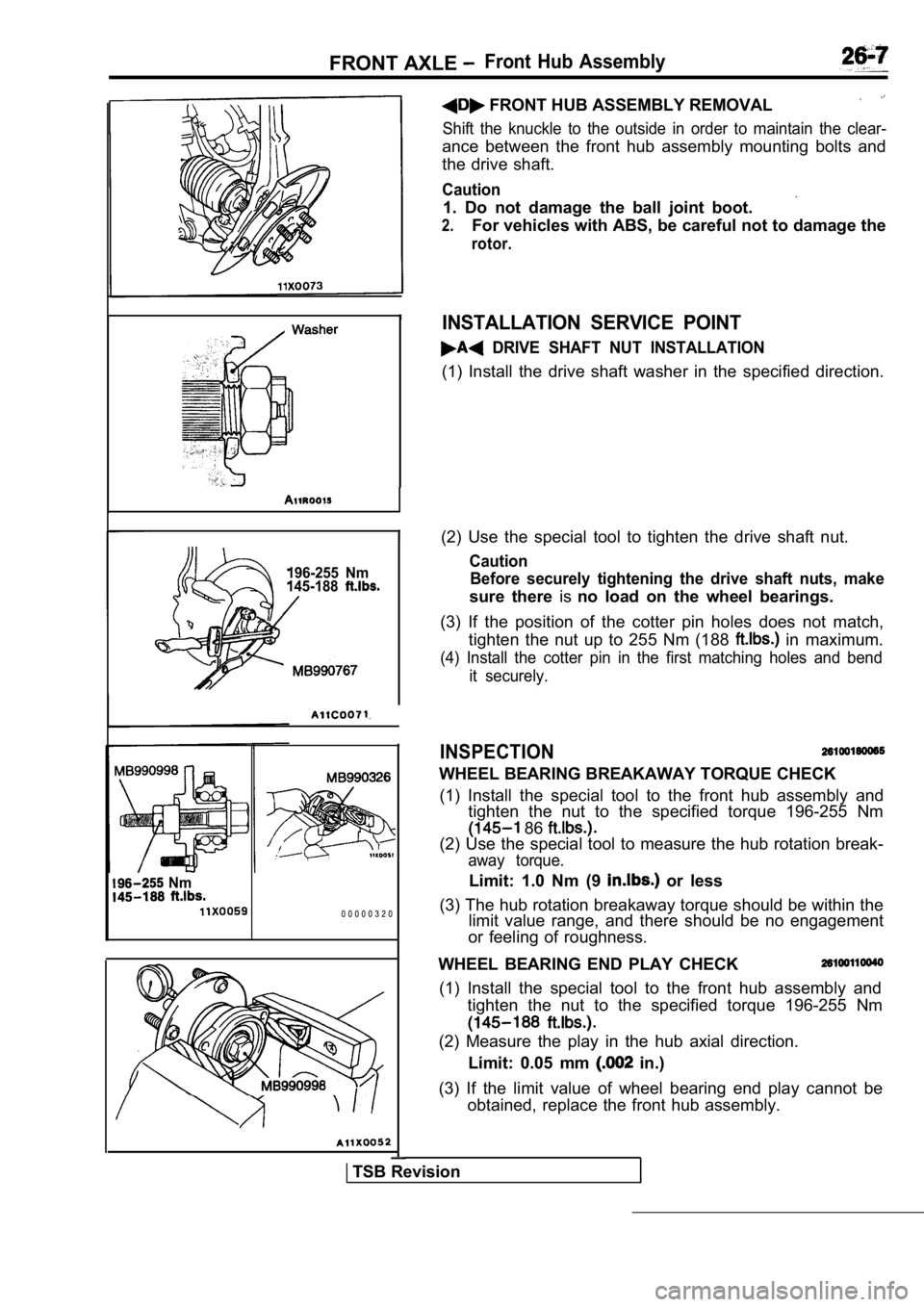
FRONT AXLE Front Hub Assembly
196-255 Nm
145-188
I(2) Use the special tool to tighten the drive shaft nut.
Caution
Before securely tightening the drive shaft nuts, ma ke
sure there isno load on the wheel bearings.
(3) If the position of the cotter pin holes does no t match,
tighten the nut up to 255 Nm (188
in maximum.
(4) Install the cotter pin in the first matching ho les and bend
it securely.
INSPECTION
WHEEL BEARING BREAKAWAY TORQUE CHECK
(1) Install the special tool to the front hub assem bly and
tighten the nut to the specified torque 196-255 Nm
86
(2) Use the special tool to measure the hub rotatio n break-
away torque.
Limit: 1.0 Nm (9 or less
(3) The hub rotation breakaway torque should be wit hin the
limit value range, and there should be no engagemen t
or feeling of roughness. Nm
0 0 0 0 0 3 2 0
FRONT HUB ASSEMBLY REMOVAL
Shift the knuckle to the outside in order to mainta in the clear-
ance between the front hub assembly mounting bolts and
the drive shaft.
Caution
1. Do not damage the ball joint boot.
2.For vehicles with ABS, be careful not to damage the
rotor.
INSTALLATION SERVICE POINT
DRIVE SHAFT NUT INSTALLATION
(1) Install the drive shaft washer in the specified direction.
WHEEL BEARING END PLAY CHECK
(1) Install the special tool to the front hub assem bly and
tighten the nut to the specified torque 196-255 Nm
(2) Measure the play in the hub axial direction.
Limit: 0.05 mm
in.)
(3) If the limit value of wheel bearing end play ca nnot be
obtained, replace the front hub assembly.
TSB Revision
Page 1536 of 2103
General Information/Service Specifications/
REAR AXLE Special Tools
The rear axle consists of a knuckle, rear hub, unit
bearing and axle shaft. The unit bearing is
fitted to the rear axle shaft and bolted to the knuckle.
Also, the unit bearing utilizes the same type of
double row angular contact ball bearing as does
the front axle.
On, ABS, a ABS rotor
for detecting the speed is located on the
and sensor is located on
the knuckle.
Rear rotor
UnitOil seal
Items
Wheel bearing end play mm (in.)
Wheel bearing rotary-sliding resistance
(Ibs.) Limit
, ,
0.05
1 8 ( 3 . 9 )
ToolTool number and name
113
Steering linkage puller
248
Inner shaft remover
Supersession Application,
Toe’ arm ball and
k n u c k l e r e m o v a l ’
.
I
. .
TSB Revision
Page 1539 of 2103
REAR AXLE Rear Hub Assembly
REMOVAL AND INSTALLATION
54-65
a
54-65
8
8
0 0 0 0 4 0 4 5
Removal steps
1. Rear wheel speed sensor
(Refer to GROUP WheelSpeed Sensor.)2.Caliper assembly3. Brake drum
4. Brake disc 5. Clip mounting bolt
6. Shoe and lining assembly (Refer
GROUP 36 Parking Brake.)
7. Rear hub assembly 8. ABS with
CautionThe rear hub assembly should not be disassembled.
TSB Revision