1990 MITSUBISHI SPYDER ABS
[x] Cancel search: ABSPage 530 of 2103
ENGINE (TURBO)
AND
ENGINE> Troubleshooting
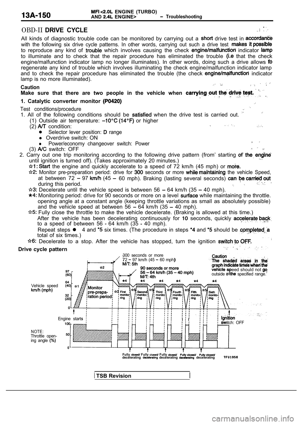
OBD-IIDRIVE CYCLE.
All kinds of diagnostic trouble code can be monitor ed by carrying out a drive test in
with the following six drive cycle patterns. In other words, carrying out such a drive test
to reproduce any kind of which involves causing the check indicator
to illuminate and to check that the repair procedur e has eliminated the trouble that the check
engine/malfunction indicator lamp no longer illumin ates). In other words, doing such a drive allows
regenerate any kind of trouble which involves illuminating the check engine/malfunction indicator lamp
and to check the repair procedure has eliminated th e trouble (the check
indicator
lamp is no more illuminated).
Caution
Make sure that there are two people in the vehicle when
1. Catalytic converter monitor
Test conditions/procedure
1. All of the following conditions should be when the drive test is carried out.
(1) Outside air temperature: or higher
(2)
condition:
Selector lever position: range
l Overdrive switch: ON
lPower/economy changeover switch: Power,
(3) switch: OFF
2. Carry out one trip monitoring according to the f ollowing drive pattern (from’ starting
until ignition is turned off). (Takes approximately 20 minutes.)
the engine and quickly accelerate to a speed of 72 km/h (45 mph) or
Monitor pre-preparation period: drive for seconds or more the vehicle Speed,
at between 72 97 (45
during this period.60 mph). Braking (lasting several seconds) . .,
Decelerate until the vehicle speed is between 56 64 km/h (35 40 mph).
Monitoring period: drive for 90 seconds or more on
a level while maintaining the throttle.
opening angle at a constant angle (keeping throttle variations as small as absolutely possible)
and the vehicle speed at between 56
64 km/h (35 40 mph).
Fully close the throttle to make the vehicle decel erate. (Braking is allowed at this time.)
After the vehicle has been decelerating continuousl y for
seconds, quickly
to a speed of between 56 64 km/h (35 40 mph).
Repeat steps l 4 and
six times. (The procedure in steps and should be
total of six times.)
Decelerate to a stop. After the vehicle has stoppe d, turn the ignition
Drive cycle pattern
300 seconds or more
72 97 km/h (45 60 mph)
eed should not outside specified range.’
Vehicle speed
NOTE:Throttle open-ing angle
0
itch: OFF
Engine startsI I
Fully Fully Fully decelerating decelerating decelerating
TSB Revision
Page 531 of 2103
ENGINE (TURBO)
AND
ENGINE>
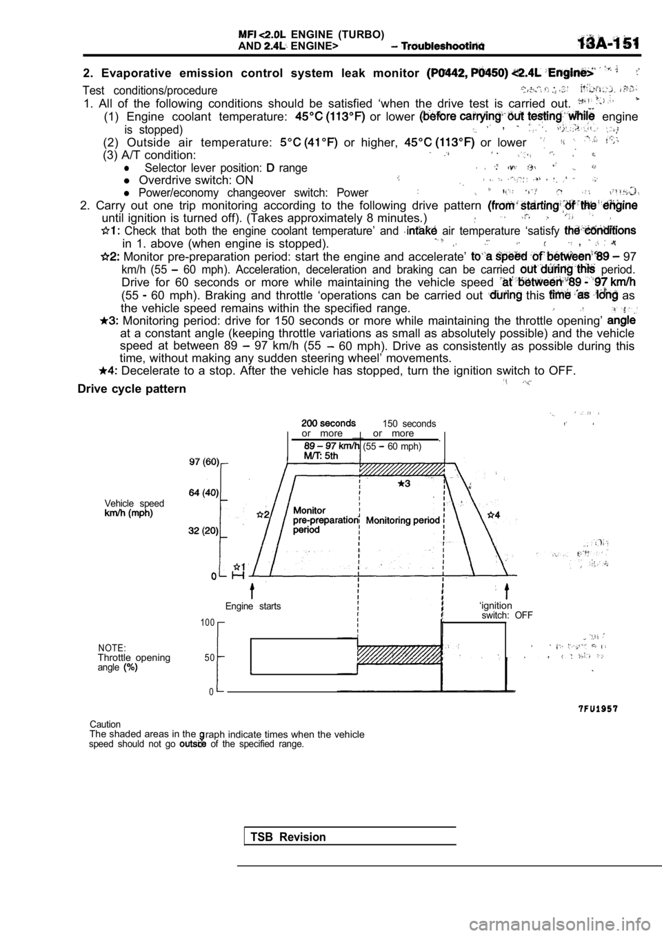
2. Evaporative emission control system leak monitor
Test conditions/procedure , . .
1. All of the following conditions should be satisfied ‘when the drive test is carried out.
(1) Engine coolant temperature: or lower engine
is stopped) ,
(2) Outside air temperature: or higher, or lower
(3) A/T condition: .
lSelector lever position: range .
l Overdrive switch: ON
l Power/economy changeover switch: Power
2. Carry out one trip monitoring according to the f ollowing drive pattern
until ignition is turned off). (Takes approximately 8 minutes.)
Check that both the engine coolant temperature’ an d air temperature ‘satisfy
in 1. above (when engine is stopped). ,
Monitor pre-preparation period: start the engine and accelerate’ 97
km/h (55 60 mph). Acceleration, deceleration and braking ca n be carried period.
Drive for 60 seconds or more while maintaining the vehicle speed
(55 60 mph). Braking and throttle ‘operations can be carried out this as
the vehicle speed remains within the specified rang e.
Monitoring period: drive for 150 seconds or more w hile maintaining the throttle opening’
at a constant angle (keeping throttle variations as small as absolutely possible) and the vehicle
speed at between 89
97 km/h (55 60 mph). Drive as consistently as possible during this
time, without making any sudden steering wheel’ mov ements.
Decelerate to a stop. After the vehicle has stopped, turn the ignition switch to OFF.
Drive cycle pattern
150 seconds
Vehicle speed
NOTE:Throttle openingangle
or more __ or more
.
(55 60 mph)
Engine starts
1 0 0
50
0
I
‘ignitionswitch: OFF
,
CautionThe shaded areas in theraph indicate times when the vehiclespeed should not go of the specified range.
TSB Revision
Page 532 of 2103
ENGINE (TURBO)
AND
ENGINE> Troubleshooting
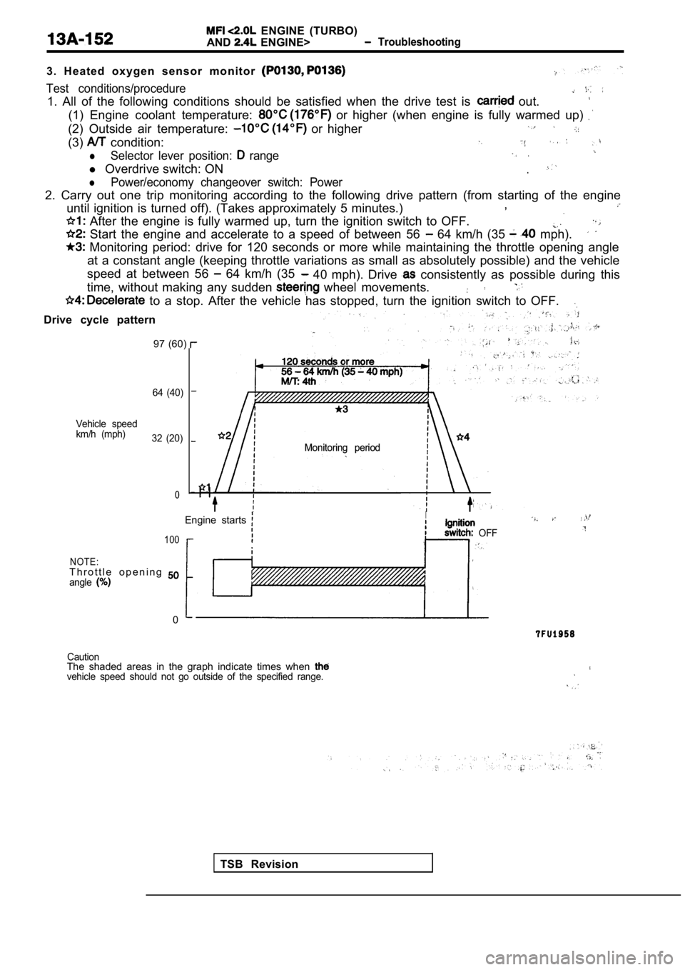
3 . H e a t e d o x y g e n s e n s o r m o n i t o r
Test conditions/procedure
1. All of the following conditions should be satisf ied when the drive test is out.
(1) Engine coolant temperature: or higher (when engine is fully warmed up)
(2) Outside air temperature: or higher
(3) condition:
lSelector lever position: range
l Overdrive switch: ON.
lPower/economy changeover switch: Power
2. Carry out one trip monitoring according to the f ollowing drive pattern (from starting of the engine
until ignition is turned off). (Takes approximately 5 minutes.),
After the engine is fully warmed up, turn the igni
tion switch to OFF.
Start the engine and accelerate to a speed of betw een 56 64 km/h (35 mph).
Monitoring period: drive for 120 seconds or more w hile maintaining the throttle opening angle
at a constant angle (keeping throttle variations as small as absolutely possible) and the vehicle
speed at between 56
64 km/h (35 40 mph). Drive consistently as possible during this
time, without making any sudden
wheel movements.
to a stop. After the vehicle has stopped, turn the ignition switch to OFF.
Drive cycle pattern
97 (60)
64 (40)
Vehicle speed
km/h (mph) 32 (20)
0
Monitoring period
Monitoring period
TSB Revision
Engine starts
I. .
OFF100
NOTE:T h r o t t l e o p e n i n g angle
0
CautionThe shaded areas in the graph indicate times when vehicle speed should not go outside of the specifie
d range.
Page 574 of 2103
![MITSUBISHI SPYDER 1990 Service Repair Manual E N G I N E
A N D ,
Code No. Differential
Malfunction
[Comment]BackgroundManifold differential se.
l pressure in the intake manifold. o r l o o s e Engine control. lThe engine co MITSUBISHI SPYDER 1990 Service Repair Manual E N G I N E
A N D ,
Code No. Differential
Malfunction
[Comment]BackgroundManifold differential se.
l pressure in the intake manifold. o r l o o s e Engine control. lThe engine co](/manual-img/19/57345/w960_57345-573.png)
E N G I N E
A N D ,
Code No. Differential
Malfunction
[Comment]BackgroundManifold differential se.
l pressure in the intake manifold. o r l o o s e Engine control. lThe engine control module checks whether the voltage output by manifold differential sure sensor is within a specified range.
Check Area, Judgement Criteria.
1. Check Areal min or more have passed after the engine was start ed.[However, this is only when the engine coolant temperature is or lower
when the engine is started.]
Engine coolant temperature is not lower than Intake air temperature is not lower than Barometric pressure is 76 (11 psi.) or higher. Volumetric efficiency is 30% 55%.
Judgement Criteria . ,
Sensor output voltage has continued to be not lowe
r than [corresponding toan absolute pressure of 118 (17 psi) or higher] for 4 sec.orSensoroutput voltage has continued to be not higher than 0.1 [corresponding to ---
an absolute pressure of 2.4 (0.3 psi) or lower] for 4 sec.
2. Check Area
8 min or more have passed engine Started.
[However, this is only when the engine coolant or lower when the engine is Engine coolant temperature is not lower than Intake air temperature is not lower than Barometric pressure is 76 (11 psi.) or higher. Volumetric efficiency is 30% or lower.
Judgement Criteria ,
l Sensor output voltage is 4.2 or higher for 4 seconds [absolute pressure is 108 (16 psi.) or more]
Check Area 8 min or more have passed after the engine was sta rted.
,
.
. , ,
[However, this is only when the engine coolant temperature is or lowerwhen engine is started.]
l Engine coolant temperature is not lower than .l Intake air temperature is not lower than l Barometric pressure is 76 (11 psi.) or higher. Volumetric efficiency is 70% or higher.
Judgement Criterial Sensor output voltage is or lower for 4 seconds [absolute pressure is 46 (6.7 psi.) or less]I
TSB Revision.
Page 639 of 2103
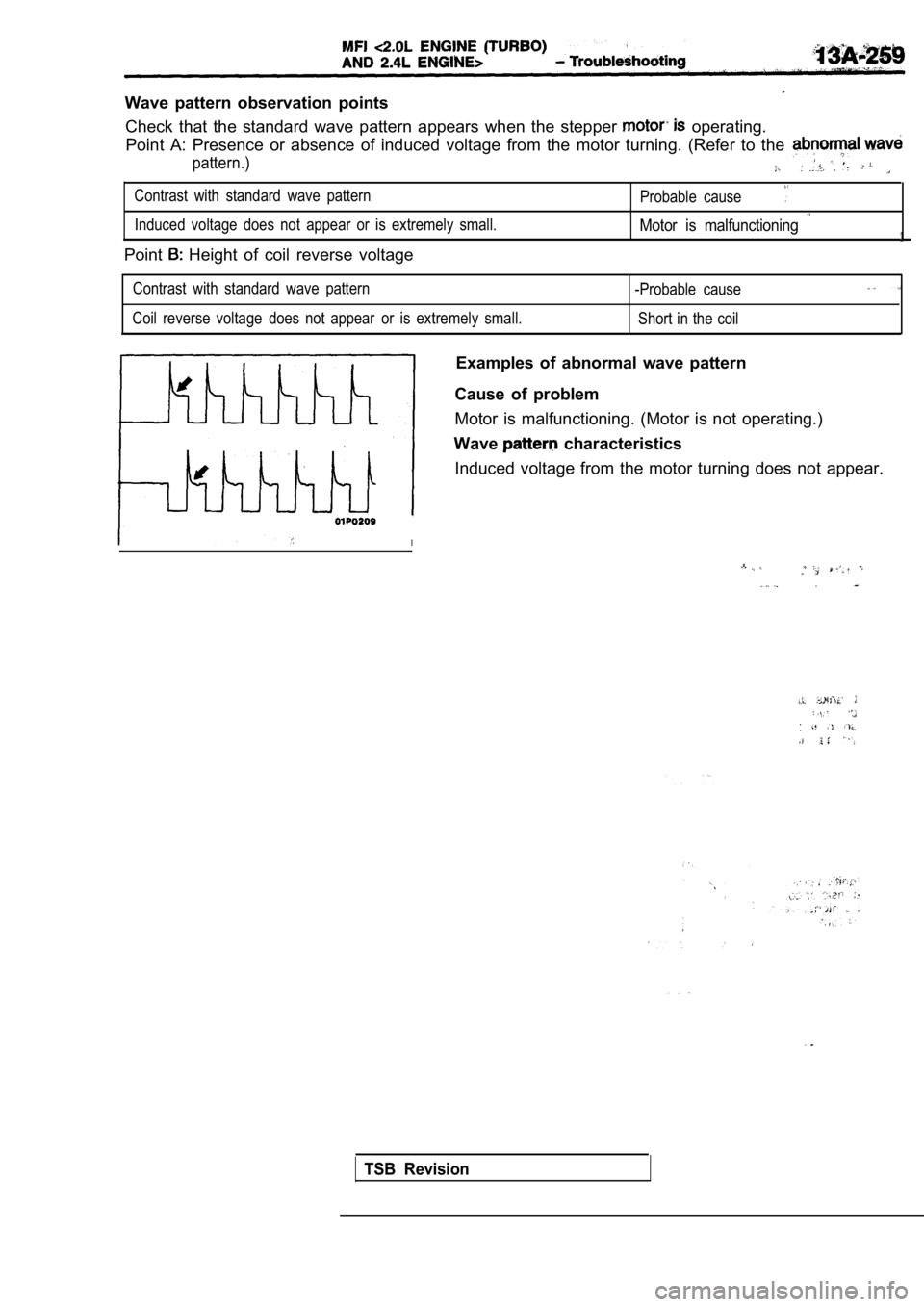
Wave pattern observation pointsCheck that the standard wave pattern appears when t he stepper
operating.
Point A: Presence or absence of induced voltage fro m the motor turning. (Refer to the
pattern.)
Contrast with standard wave pattern
Probable cause
Induced voltage does not appear or is extremely small.Motor is malfunctioning
Point Height of coil reverse voltage
Contrast with standard wave pattern
-Probable cause
Coil reverse voltage does not appear or is extremely small.
Short in the coil
Examples of abnormal wave pattern
Cause of problem
Motor is malfunctioning. (Motor is not operating.)
Wave
characteristics
Induced voltage from the motor turning does not app ear.
I
.
TSB Revision
Page 692 of 2103
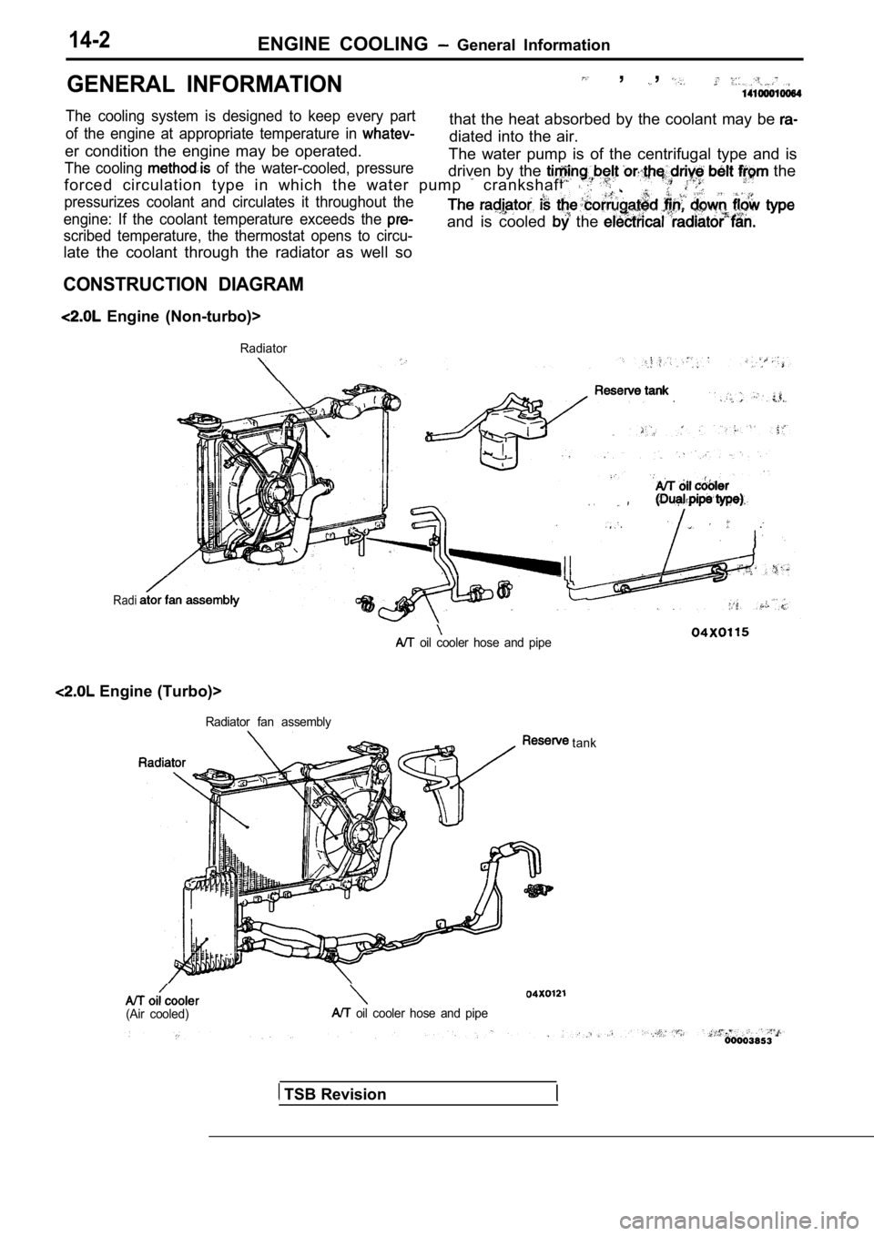
14-2ENGINE COOLING General Information
GENERAL INFORMATION , ,
The cooling system is designed to keep every partthat the heat absorbed by the coolant may be of the engine at appropriate temperature in diated into the air.
er condition the engine may be operated.
The cooling of the water-cooled, pressureThe water pump is of the centrifugal type and is
driven by the
the
forced circulation type in which the water pump crankshaft. .
pressurizes coolant and circulates it throughout th e
engine: If the coolant temperature exceeds the
scribed temperature, the thermostat opens to circu-
late the coolant through the radiator as well so
and is cooled the
CONSTRUCTION DIAGRAM
Engine (Non-turbo)>
Radiator
Radi
.
oil cooler hose and pipe
Engine (Turbo)>
Radiator fan assembly
(Air cooled) oil cooler hose and pipetank
TSB Revision
Page 704 of 2103

ENGINE Thermostat
EngineJiggle valve
Engine Jiggle valve
Rubber
ring
Projection
Walter outlet fitting or
water inlet fitting
R E M O V A L S E R V I C E P O I N T
UPPER HOSE
(Non-turbo)> OR ROSE
Engine and. ,
D I S C O N N E C T I O N ,
Place a mating mark on the and the clamp.
Then, disconnect the hose.
INSTALLATION SERVICE POINTS
THERMOSTAT INSTALLATION
Install the thermostat so that the jiggle valve is
facing straight
up and is aligned with the mark on the thermostat c ase as
shown in the illustration.
Caution
Make absolutely sure that no oil is adhering to the rubber
ring of the thermostat. In addition, be careful not fold
over or scratch the rubber ring
UPPER HOSE Engine
(Non-Turbo)> OR RADIATOR LOWER
Engine (Turbo) and Engine>
CONNECTION
(1) Insert each hose as far as the of the water
outlet fitting or water inlet fitting.
(2) Align the mating marks on the radiator hose and hose
clamp, and then connect the radiator hose.
.
Revision
Page 740 of 2103
INTAKE AND Pipe and Main
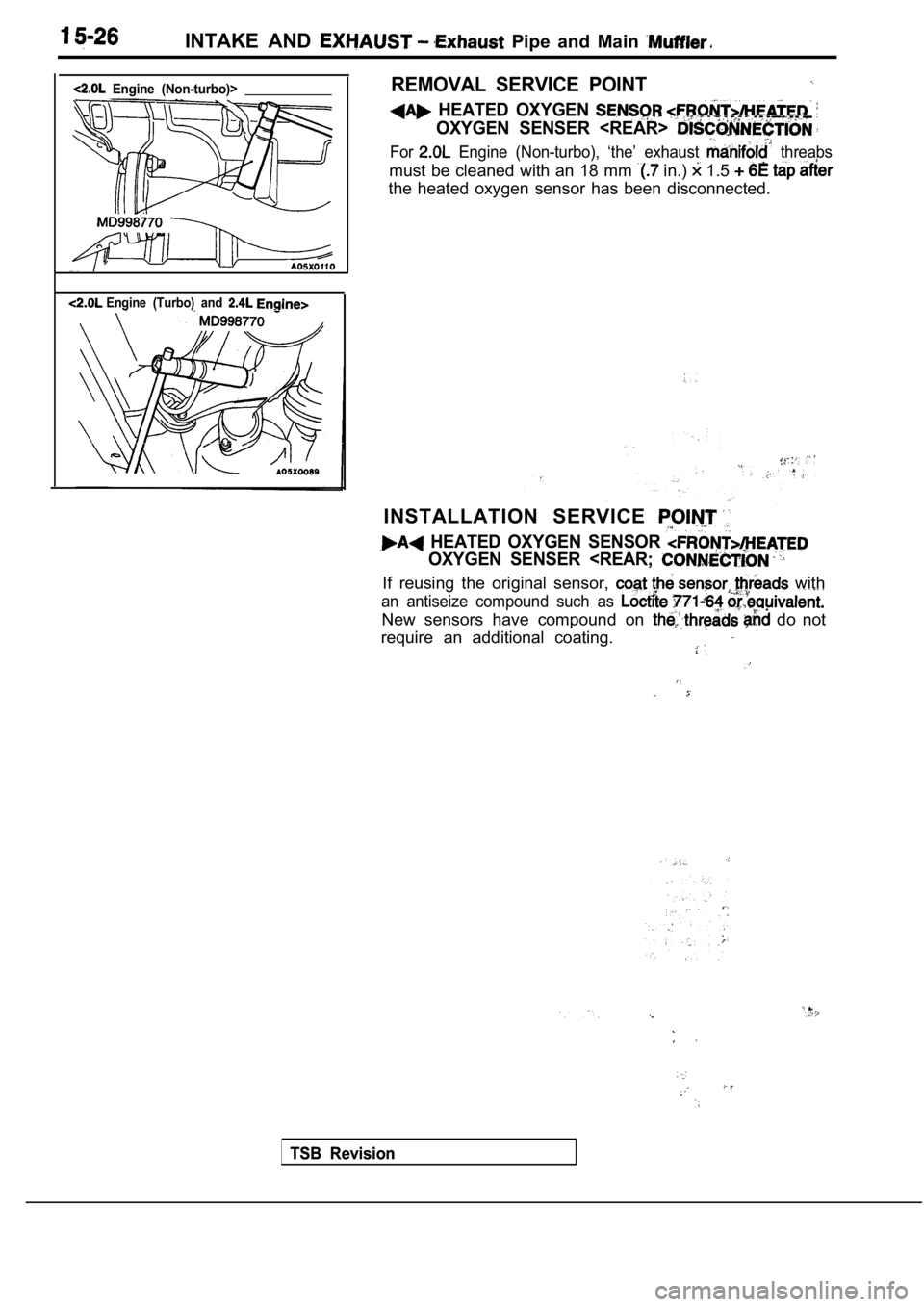
Engine (Non-turbo)>
Engine (Turbo) and
REMOVAL SERVICE POINT
HEATED OXYGEN
OXYGEN SENSER
For Engine (Non-turbo), ‘the’ exhaust threabs
must be cleaned with an 18 mm in.) 1.5
the heated oxygen sensor has been disconnected.
INSTALLATION SERVICE
HEATED OXYGEN SENSOR
OXYGEN SENSER
an antiseize compound such as
New sensors have compound on do not
require an additional coating.
TSB Revision
TSB Revision