1990 MITSUBISHI SPYDER turn signal
[x] Cancel search: turn signalPage 527 of 2103

E N G I N E ( T U R B O )
AND
ENGINE>
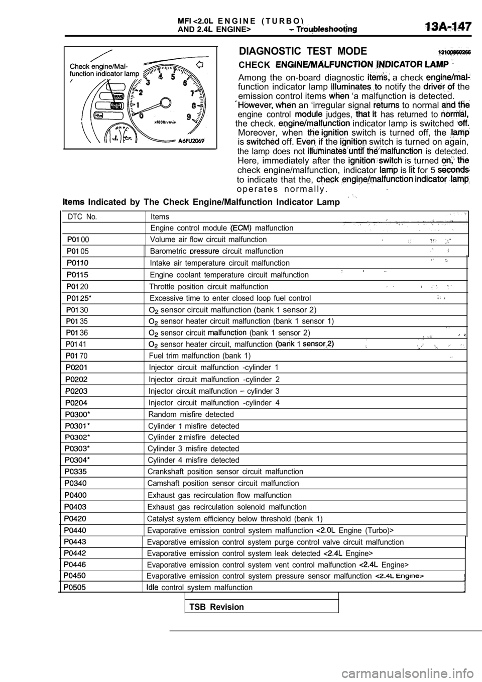
DIAGNOSTIC TEST MODE
CHECK
Among the on-board diagnostic a check
function indicator lamp notify the the
emission control items
‘a malfunction is detected.
an ‘irregular signal to normal
engine control judges, has returned to
the check. indicator lamp is switched
Moreover, when switch is turned off, the
is off. if the switch is turned on again,
the lamp does not is detected.
Here, immediately after the is turned
check engine/malfunction, indicator is for 5
to indicate that the,
o p e r a t e s n o r m a l l y .
Indicated by The Check Engine/Malfunction Indicato r Lamp
00
05
20
30
35
36
41
70
Items
Engine control module
malfunction
Volume air flow circuit malfunction
Barometric
circuit malfunction
Intake air temperature circuit malfunction
Engine coolant temperature circuit malfunction
Throttle position circuit malfunction
Excessive time to enter closed loop fuel control
sensor circuit malfunction (bank 1 sensor 2)
sensor heater circuit malfunction (bank 1 sensor 1 )
sensor circuit (bank 1 sensor 2).
sensor heater circuit, malfunction 1
Fuel trim malfunction (bank 1)
Injector circuit malfunction -cylinder 1
Injector circuit malfunction -cylinder 2
Injector circuit malfunction
cylinder 3
Injector circuit malfunction -cylinder 4
Random misfire detected
Cylinder
misfire detected
Cylinder
2misfire detected
Cylinder 3 misfire detected Cylinder 4 misfire detected
Crankshaft position sensor circuit malfunction
Camshaft position sensor circuit malfunction
Exhaust gas recirculation flow malfunction
Exhaust gas recirculation solenoid malfunction
Catalyst system efficiency below threshold (bank 1) Evaporative emission control system malfunction
Engine (Turbo)>
Evaporative emission control system purge control v alve circuit malfunction
Evaporative emission control system leak detected
Engine>
Evaporative emission control system vent control ma lfunction
Engine>
Evaporative emission control system pressure sensor malfunction
control system malfunction
DTC No.
TSB Revision
Page 529 of 2103

E N G I N E
AND ENGINE>
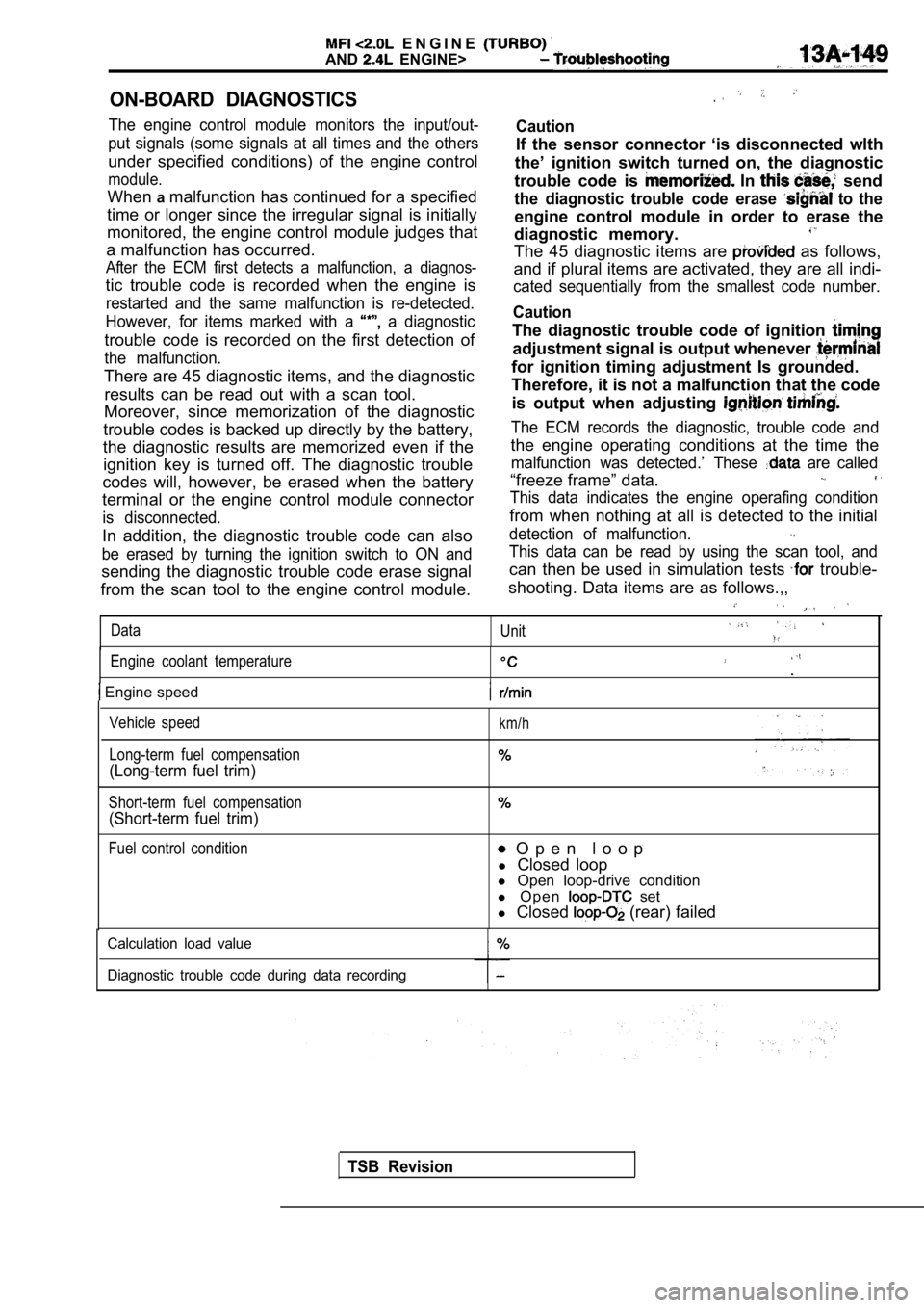
ON-BOARD DIAGNOSTICS
The engine control module monitors the input/out-
put signals (some signals at all times and the othe rs
under specified conditions) of the engine control
module.
Whenamalfunction has continued for a specified
time or longer since the irregular signal is initia lly
monitored, the engine control module judges that
a malfunction has occurred.
After the ECM first detects a malfunction, a diagno s-
tic trouble code is recorded when the engine is
restarted and the same malfunction is re-detected.
However, for items marked with a
a diagnostic
trouble code is recorded on the first detection of
the malfunction.
There are 45 diagnostic items, and the diagnostic results can be read out with a scan tool.
Moreover, since memorization of the diagnostic
trouble codes is backed up directly by the battery,
the diagnostic results are memorized even if the ignition key is turned off. The diagnostic trouble
codes will, however, be erased when the battery
terminal or the engine control module connector
is disconnected.
In addition, the diagnostic trouble code can also
be erased by turning the ignition switch to ON and
sending the diagnostic trouble code erase signal
from the scan tool to the engine control module.
Caution
If the sensor connector ‘is disconnected wlth
the’ ignition switch turned on, the diagnostic
trouble code is
In send
the diagnostic trouble code erase to the
engine control module in order to erase the
diagnostic memory.
The 45 diagnostic items are as follows,
and if plural items are activated, they are all ind i-
cated sequentially from the smallest code number.
Caution
The diagnostic trouble code of ignition
adjustment signal is output whenever
for ignition timing adjustment Is grounded.
Therefore, it is not a malfunction that the code
is output when adjusting
The ECM records the diagnostic, trouble code and
the engine operating conditions at the time the
malfunction was detected.’ These are called
“freeze frame” data.
This data indicates the engine operafing condition
from when nothing at all is detected to the initial
detection of malfunction.
This data can be read by using the scan tool, and
can then be used in simulation tests trouble-
shooting. Data items are as follows.,,
Data Unit
Engine coolant temperature.
Engine speed
Vehicle speed
Long-term fuel compensation
(Long-term fuel trim)
Short-term fuel compensation
(Short-term fuel trim)
km/h
Fuel control condition O p e n l o o p
l Closed loop
l Open loop-drive condition
l O p e n
set
l Closed
(rear) failed
Calculation load value
Diagnostic trouble code during data recording
TSB Revision
Page 538 of 2103

ENGINE
A N D E N G I N E > .
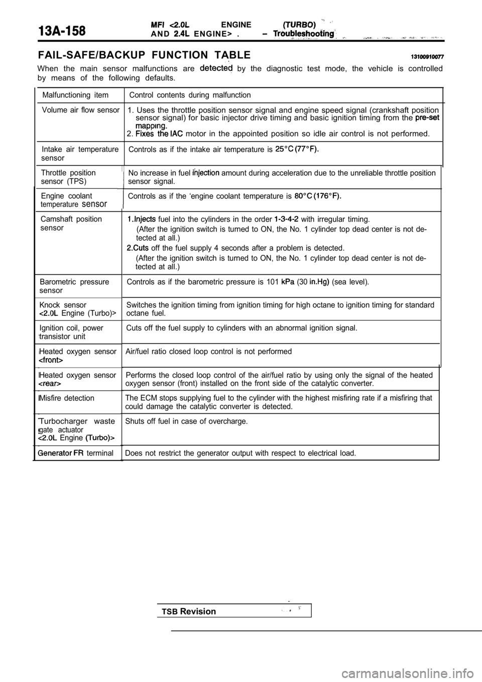
FAIL-SAFE/BACKUP FUNCTION TABLE
When the main sensor malfunctions are by the diagnostic test mode, the vehicle is controlled
by means of the following defaults.
Malfunctioning item Control contents during malfunct ion
Volume air flow sensor
1. Uses the throttle position sensor signal and eng ine speed signal (crankshaft position
sensor signal) for basic injector drive timing and basic ignition timing from the
2. motor in the appointed position so idle air contro l is not performed.
Intake air temperature
Controls as if the intake air temperature is
sensor
Throttle position
sensor (TPS)
Engine coolant
temperaturesensor
Camshaft position
sensor
Barometric pressure
sensor
Knock sensor
Engine (Turbo)>
Ignition coil, power
transistor unit
Heated oxygen sensor
Heated oxygen sensor
Misfire detection
Turbocharger waste
gate actuator Engine
terminal Performs the closed loop control of the air/fuel ra
tio by using only the signal of the heated
oxygen sensor (front) installed on the front side o f the catalytic converter.
The ECM stops supplying fuel to the cylinder with t he highest misfiring rate if a misfiring that
could damage the catalytic converter is detected.
Shuts off fuel in case of overcharge.
Does not restrict the generator output with respect to electrical load.
No increase in fuel amount during acceleration due to the unreliable throttle position
sensor signal.
Controls as if the ‘engine coolant temperature is
fuel into the cylinders in the order with irregular timing.
(After the ignition switch is turned to ON, the No. 1 cylinder top dead center is not de-
tected at all.)
off the fuel supply 4 seconds after a problem is d etected.
(After the ignition switch is turned to ON, the No. 1 cylinder top dead center is not de-
tected at all.)
Controls as if the barometric pressure is 101
(30 (sea level).
Switches the ignition timing from ignition timing f or high octane to ignition timing for standard
octane fuel.
Cuts off the fuel supply to cylinders with an abnor mal ignition signal.
Air/fuel ratio closed loop control is not performed
TSB Revision
Page 559 of 2103
![MITSUBISHI SPYDER 1990 Service Repair Manual ENGINE (TURBO)
AND ENGINE> Troubleshooting
Code No. Exhaust Gas Recirculation Flow MalfunctionProbable
[Comment]l EGR valve does not openBackgroundl EGR control vacuum is too lowl MITSUBISHI SPYDER 1990 Service Repair Manual ENGINE (TURBO)
AND ENGINE> Troubleshooting
Code No. Exhaust Gas Recirculation Flow MalfunctionProbable
[Comment]l EGR valve does not openBackgroundl EGR control vacuum is too lowl](/manual-img/19/57345/w960_57345-558.png)
ENGINE (TURBO)
AND ENGINE> Troubleshooting
Code No. Exhaust Gas Recirculation Flow MalfunctionProbable
[Comment]l EGR valve does not openBackgroundl EGR control vacuum is too lowlWhen the EGR solenoid switches from OFF to ON while the engine is running, EGRl EGR solenoid failedgas flows.lOpen or shorted EGR solenoid circuit, or l The engine control module checks how the EGR gas fl ow signal changes.connector
Check Areal Manifold differential pressure sensor failed
l Engine coolant temperature is higher than l Engine control failedl Engine speed is between 1000 and 2000 l Engine speed is between 940 and 2000 .
l Intake air temperature is
or higher.
l Barometric pressure is 76 (11 psi.) or higher.
l Closed throttle position switch: ON
l Volumetric efficiency is 15%
or 27% or lower. engine l Volumetric efficiency is 15% or 20% or lower. engine>
l Monitoring Time: 2
Judgement Criterial There is no change in the condition of the air inta ke system when the EGR solenoid
is turned on.
l Monitored only once per trip.
Check the EGR system (Refer to GROUP 17 Emission Control(Refer to GROUP 17 Emission System) Engine EGR solenoid
(Refer to GROUP 17 Emission Control System)
OK
Replace,
Check the following items.
l Vacuum hoses
l EGR
vacuum7
l EGR valve
Check the manifold differential pressure sensor malfunction95 Manifold differential pressure sensor (Refer to (Refer to INSPECTION PROCEDURE FOR TROUBLE CODE
Check for EGR valve and EGR line blockages, and cle an if
TSB Revision
Page 571 of 2103
![MITSUBISHI SPYDER 1990 Service Repair Manual ENGINE (TURBO)
AND ENGINE> Troubleshooting
Code No. Power Steering Pressure Sensor CircuitProbable cause
[Comment] Power pressure switch Backgroundl Open or shorted power steering MITSUBISHI SPYDER 1990 Service Repair Manual ENGINE (TURBO)
AND ENGINE> Troubleshooting
Code No. Power Steering Pressure Sensor CircuitProbable cause
[Comment] Power pressure switch Backgroundl Open or shorted power steering](/manual-img/19/57345/w960_57345-570.png)
ENGINE (TURBO)
AND ENGINE> Troubleshooting
Code No. Power Steering Pressure Sensor CircuitProbable cause
[Comment] Power pressure switch Backgroundl Open or shorted power steering pressurelWhen the steering wheel is kept in the position during driving, the power
s w i t c h or steering pressure switch will be momentarily turned off. E n g i n e c o n t r o l f a i l e d ’lThe enginecontrol module checks whetherthe powerste ering pressure switch momentarilyturns off during driving.
Check Area Engine coolant temperature is or higher.
l Driving and stopping ‘2 are repeated times or more.“1: Engine speed is 2,500 or higher, volumetric efficiency is 55% or higher, and this
condition continues for 2 seconds or more.
l 2: Engine speed is 600 or lower.
Judgement Criterial Power steering pressure switch stays on without cha nging.
NGCheck the power steering press On-vehicle Service) Replace
lDisconnect the connector and measure at the harness side.
NG
between ECM and power pressure switch
NG
the ECM. Replace the ECM.
Code No. Transmission Range Sensor Circuit
Malfunction (RPNDL Input)
[Comment]
Background
lWhen a malfunction of the park/neutral position swi tch is detected, the transaxle control
module outputs amalfunction signal to the engine control module.
Check Area, Judgement Criteria l
control module.
Check the TCM. (Refer to GROUP Troubleshooting.)
Repair
Repair
cause
l Park/neutral position switch failedlOpen or shorted park/neutral position switchcircuit, or loose connector.
l Engine control module failed.
Code No. Turbocharger Waste Gate Actuator
Malfunction
(Turbo)> Probable cause
l
Turbocharger waste gateactuator failed.
l Charging pressure control system failed.
l Engine control module failed.[Comment]
Background
lThe engine control module checks that the engine is not overcharged by always monitoringintake air volume.lThe engine control module protects the engine by shutting off fuel when an overcharged
condition is detected.
Check Area
Engine coolant temperature is higher than
Judgement Criterial Volumetric efficiency has continued to be not lower than 200% for 1.5 sec.
Check the turbocharger supercharging. (Refer to GROUP 15
On-vehicle Service.)
TSB Revision
Page 600 of 2103
![MITSUBISHI SPYDER 1990 Service Repair Manual ENGINE (TURBO)
AND ENGINE>
INSPECTION PROCEDURE 27
Power supply system and ignition systemP r o b a b l e
[Comment]l Malfunction of the ignition switchWhen an ignition switch ON sign MITSUBISHI SPYDER 1990 Service Repair Manual ENGINE (TURBO)
AND ENGINE>
INSPECTION PROCEDURE 27
Power supply system and ignition systemP r o b a b l e
[Comment]l Malfunction of the ignition switchWhen an ignition switch ON sign](/manual-img/19/57345/w960_57345-599.png)
ENGINE (TURBO)
AND ENGINE>
INSPECTION PROCEDURE 27
Power supply system and ignition systemP r o b a b l e
[Comment]l Malfunction of the ignition switchWhen an ignition switch ON signal is input to the E CM, the ECM turns the relay ON. Thisl Malfunction of the relaycauses battery positive voltage to be supplied to t he injectors and volume air flow sensor.Improper connector contact, open or
short-circuited harness wire
l .-Disconnected
wirel Malfunction of the ECM
Check the
relay. (Refer to Replace
OK NG
Measure at the relay connector Check the harness wire battery and lDisconnect the connector, and measure at the harnes sRepair, if necessary.side.l between 3, 4 and aroundOK: Battery positive voltage
OK
Check the ECM power and around circuit. ( R e f e r PR O C E D U R E 4 4 . )
INSPECTION PROCEDURE 28
Fuel pump system Engine (Turbo)>Probable cause
[Comment]l Malfunction of the fuel pump relay The ECM turns the fuel pump relay ON when the engin e is cranking or running, and this M a l f u n c t i o n o f ,
plies power to drive the fuel pump. Improper connector open short-circuited harness wire
l Malfunction of the
Check the fuel pump circuit.
(Refer to I N S P E C T I O N P R O C E D U R E .
Replace
OK .
Check the fuel pump drive control circuit.
Connect the connector. (Refer to INSPECTION PROCEDURE 46.)
l Voltage between 1 and ground
l SCAN TOOL Actuator test: Fuel pump drive
OK:
oositive voltaae
OK
Check the harness wire between fuel pump relay conn ectorand fuel pump drive terminal. Repair, if necessary.
TSB Revision
Page 604 of 2103
![MITSUBISHI SPYDER 1990 Service Repair Manual E N G I N E
AND ‘ENGINE> Troubleshooting
INSPECTION PROCEDURE 32
switch and compressor clutch relay system, . .
(Comment]l Malfunction of control When an A/C ON signal is i MITSUBISHI SPYDER 1990 Service Repair Manual E N G I N E
AND ‘ENGINE> Troubleshooting
INSPECTION PROCEDURE 32
switch and compressor clutch relay system, . .
(Comment]l Malfunction of control When an A/C ON signal is i](/manual-img/19/57345/w960_57345-603.png)
E N G I N E
AND ‘ENGINE> Troubleshooting
INSPECTION PROCEDURE 32
switch and compressor clutch relay system, . .
(Comment]l Malfunction of control When an A/C ON signal is input to the the ECM carries out control of the idle air control Malfunction of motor, and also operates the compressor magnetic clutch.lImproper connector open circuit or harness .
NG
(Refer toGROUP55 On-vehicleService.) Replace
OK
Measure at the ECM connectors lDisconnect the connector, and measure at the harness
lVoltage between 22 and ground, and 45 and ground
(Ignition switch: ON)
(A/C switch: ON)
OK: Battery positive voltage
l Shortcircuit between 22 and ground
(Ignition switch: ON)
switch: ON)
OK: compressor clutch turns ON.
OK
N G
OK
Check trouble symptom.
the
NG
TSB RevisionI
Page 606 of 2103
![MITSUBISHI SPYDER 1990 Service Repair Manual ENGINE (TURBO)AND Troubleshooting
INSPECTION PROCEDURE 34
Ignition circuit system cause’
[Comment]l Malfunction of ignition The interrupts the ignition coil current by turning the MITSUBISHI SPYDER 1990 Service Repair Manual ENGINE (TURBO)AND Troubleshooting
INSPECTION PROCEDURE 34
Ignition circuit system cause’
[Comment]l Malfunction of ignition The interrupts the ignition coil current by turning the](/manual-img/19/57345/w960_57345-605.png)
ENGINE (TURBO)AND Troubleshooting
INSPECTION PROCEDURE 34
Ignition circuit system cause’
[Comment]l Malfunction of ignition The interrupts the ignition coil current by turning the transistor in- of side the ECM ON and OFF.l Improper connector contact, open circuit or,
shortcircuited harness wire
l Malfunction
the ECM
Engine (Turbo)>
Measure at the ignition coil connector
lDisconnect the connector and measure at the harness
side.
l Voltage between 3 and ground (Ignition switch: ON)
OK: Battery positive voltage
Engine>
Measure at the ignition coil connectors 0, lDisconnect the connectors and measure at the harnes s
side.
l Voltage between 1 and ground (Ignition switch: ON)
OK: Battery positive voltage
OK
lDisconnect the connector, and measure at the harnes s
side.
l Continuity between 3 and ground
OK: Continuitv
Check trouble symptom.
Check the ignition switch. (Refer to Ignition Switch.)
N GCheck the harness wire between ignition connectorand ground. Repair, if necessary.
OK
Check the following connectors: EngineNG Repair(Turbo)>, Engine>, A-l 11
OK
Check trouble symptom.
NG Replace
(Refer toGROUP16 Ignition System.)
Check the ignition power tranNG Replace
(Refer to GROUP 16 Ignition
OK
lDisconnect the connector, and measure at the harnes s
side.
1. Voltage between each of 1, and ground
(Ignition switch: ON)
OK: Battery positive voltage
2.
between each of 2. 7 and around Cranking)
OK:
Check the following con- NG Repair
I
Check trouble symptom.
NGI
Check the harness wire between the ignition coil an d ignition power
transistor unit connector. Repair, if necessary.
.
Check trouble symptom.
Check trouble symptom.
NG
Check the ignition signal circuit. (Refer to INSPECTION PROCEDURE
Replace the ECM.
TSB Revision