1990 MITSUBISHI SPYDER turn signal
[x] Cancel search: turn signalPage 619 of 2103
ENGINE (TURBO)
AND ENGINE>
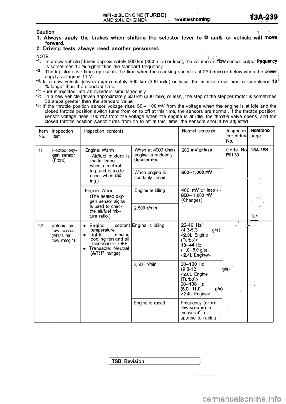
Caution
1. Always apply the brakes when shifting the select or lever to ran&, or vehicle will
forward.
2. Driving tests always need another personnel.
NOTE
In a new vehicle [driven approximately 500 km (300 mile) or less], the volume air sensor output
is sometimes 10 higher than the standard frequency.
The injector drive time represents the time when the cranking speed is at 250 or below when the
supply voltage is 11 V.
In a new vehicle [driven approximately 500 km (300 mile) or less], the injector drive time is sometimes
longer than the standard time.
Fuel is injected into all cylinders simultaneously.
In a new vehicle [driven approximately km (300 mile) or less], the step of the stepper mo tor is sometimes
30 steps greater than the standard value.
If the throttle position sensor voltage rises 100 from the voltage when the engine is at idle and th e
closed throttle position switch turns from on to of f at this time, the sensors are normal. If the throttle position
sensor voltage rises 100
from the voltage when the engine is at idle, the t hrottle valve opens, and the
closed throttle position switch turns from on to of f at this, time, the sensors should be adjusted.
Item Inspection
No.item
Inspection contents Normal contentsInspection
procedure page
11HeatedEngine: WarmWhen at 4000 200 or Code No.
gen sensor engine is suddenly(Air/fuel mixture is 30
(Front)
made leaner
when decelerat- ing, and is made
richer when
When engine is
suddenly raceding.)
Engine: Warm Engine is idling
400 or
(The heated 1,000 ,gen sensor signal(Changes)
is used to check
2,500
the air/fuel mix-
ture ratio.)
Volume airl Engine coolant Engine is idling 22-46 Hz’
flow sensortemperature(4.3-5.3 g/s)
(Mass airl
Lights,electric
flow rate) cooling fan and all Engine
accessories: OFF(Turbo)>
l Transaxle: Neutral Hz
range)(1 g/s)
2,500
Engine is raced
Hz
(9.8-12.1
Engine,
Hz ,
Engine>
Frequency (or air
flow volume) in
creases
re- ,
sponse to racing.
TSB Revision
Page 626 of 2103
E N G I N E
AND ENGINE>
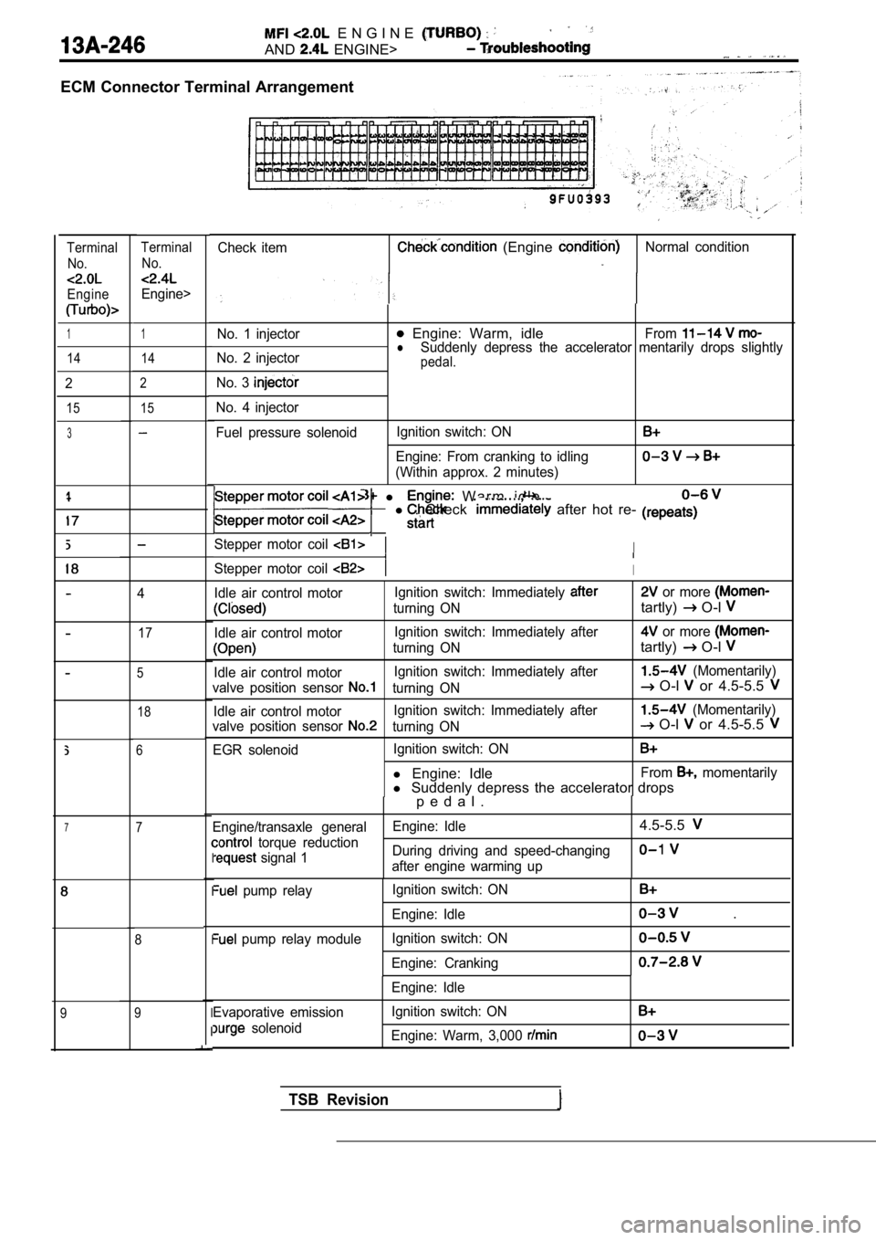
ECM Connector Terminal Arrangement
Check item (Engine Normal conditionTerminalNo.
Engine
TerminalNo.
Engine>
1No. 1 injector Engine: Warm, idleFromlNo. 2 injector Suddenly depress the accelerator mentarily drops sl
ightlypedal.
No. 3
No. 4 injector
Fuel pressure solenoidIgnition switch: ON
Engine: From cranking to idling
(Within approx. 2 minutes)
1
14 14
2
15
2
15
3
l W a r m i d l e
l . Check after hot re-
Stepper motor coil I
Stepper motor coil I
Idle air control motor Ignition switch: Immediately or more
turning ONtartly) O-l
Idle air control motorIgnition switch: Immediately after or more
turning ONtartly) O-l
Idle air control motorIgnition switch: Immediately after (Momentarily)
valve position sensor
turning ON O-l or 4.5-5.5
Idle air control motor Ignition switch: Immediately after (Momentarily)
valve position sensor
turning ON O-l or 4.5-5.5
EGR solenoid Ignition switch: ON
l
Engine: IdleFrom momentarily
l Suddenly depress the accelerator drops
4
17
5
18
6
p e d a l .
Engine/transaxle general Engine: Idle4.5-5.5
torque reduction
signal 1During driving and speed-changingafter engine warming upI
I
I
I
I
pump relay
pump relay module Ignition switch: ON
Engine: Idle
Ignition switch: ON
Engine: Cranking
.
Evaporative emission
solenoid Engine: Idle
Ignition switch: ON
Engine: Warm, 3,000
77
8
9
9
TSB Revision
Page 627 of 2103
ENGINE (TURBO)
AND ENGINE>
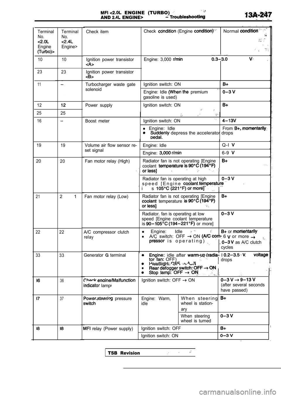
Check itemIgnition power transistorCheck (Engine Normal
Engine: 3,000 .
Ignition power transistor
Terminal No.
Engine
Terminal
No.
Engine>
10 10
23 23
11
12
Turbocharger waste gate Ignition switch: ON
solenoid
Engine: Idle premium
gasoline is used)
Power supply Ignition switch: ON
2525
Boost meter
Ignition switch: ON
l Engine: IdleFrom depress the accelerator drops
16
19
19Volume air flow sensor re- Engine: IdleQ - l
set signal
Engine:6-9
Fan motor relay (High)Radiator fan is not operating [Engine
coolant
2020
21
22
33
.
Radiator fan is operating at high
s p e e d [ E n g i n e
i s
Fan motor relay (Low)Radiator fan is not operating [Engine temperature
Radiator. fan is operating at low
speed [Engine coolant temperature
is
or more]
A/C compressor clutch
l Engine: Idle or
relaylA/C switch: OFF ON 6 or more i s o p e r a t i n g ) , as A/C clutch
cycles
2 1
22
33
ine: idle after I OFF) . . A Ndrops
II. .
Generator terminal
l
36Ignition switch: OFF ON
lamp(after several seconds
have passed)
pressureEngine: Warm,W h e n s t e e r i n g
idlewheel is station-
ary
When steering
wheel is turned
37
relay (Power supply) Ignition switch: OFF
Ignition switch: ON
TSB Revision
Page 628 of 2103
ENGINE (TURBO)
AND ENGINE> Troubleshooting
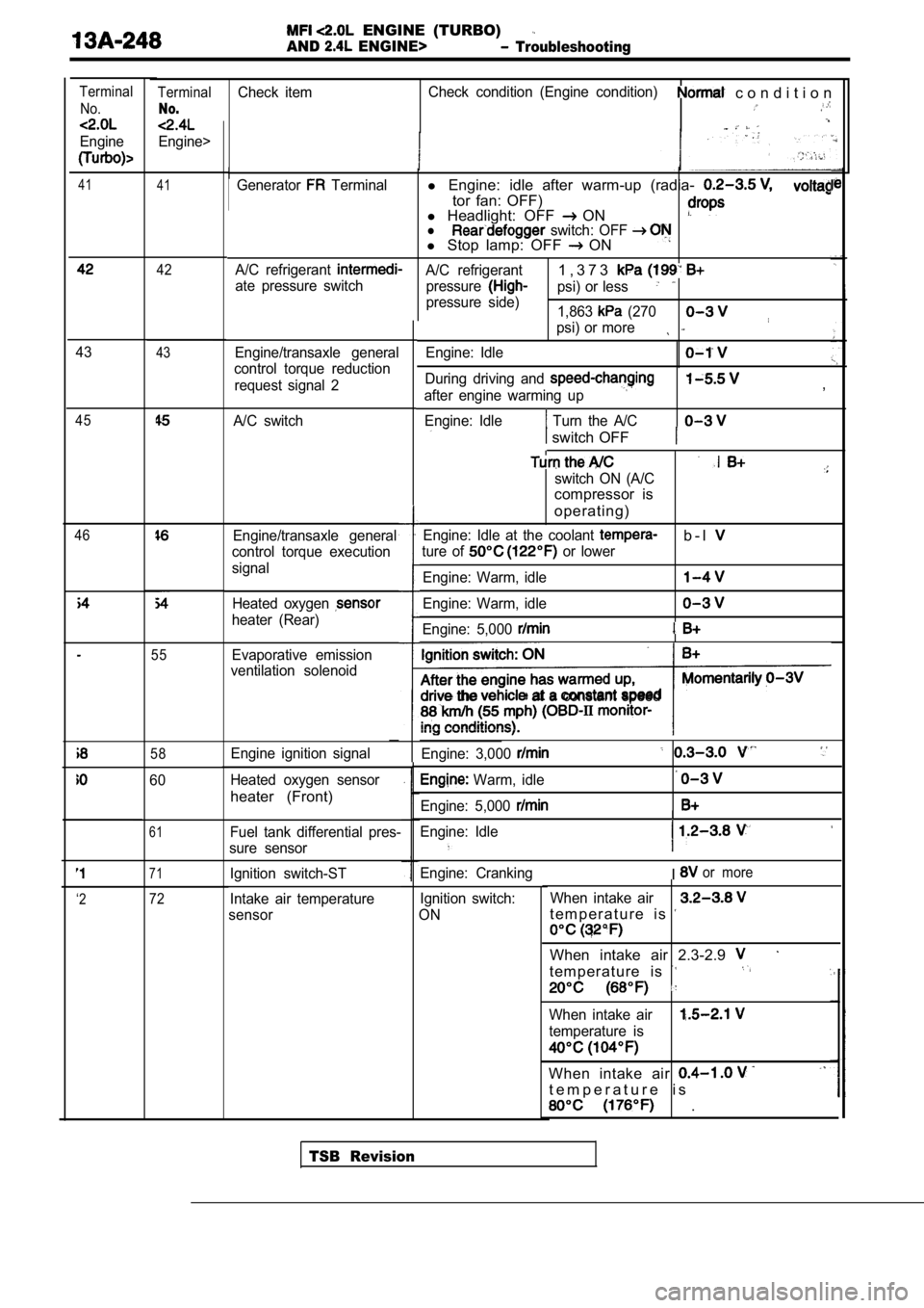
TerminalCheck itemCheck condition (Engine condition) c o n d i t i o n
No.
Engine>
Terminal
No.
Engine
41 41Generator Terminall Engine: idle after warm-up (radia-
tor fan: OFF)
l Headlight: OFF ONl switch: OFF l Stop lamp: OFF ON
A/C refrigerant A/C refrigerant1 , 3 7 3
ate pressure switch
pressurepsi) or less
pressure side)
1,863 (270
psi) or more
Engine/transaxle general
control torque reduction
request signal 2 Engine: Idle
During driving and
after engine warming up
Engine: Idle
Turn the A/C
,
switch OFF
switch ON (A/C
compressor is
operating)
Engine: Idle at the coolant b - l
ture of or lower
Engine: Warm, idle
Engine: Warm, idle
Engine: 5,000
the at a constant speed
Engine: 3,000
Warm, idle
Engine: 5,000
Engine: Idle
I
Engine: CrankingIor more
Ignition switch:
ON When intake air
t e m p e r a t u r e i s
When intake air 2.3-2.9
t e m p e r a t u r e i s
When intake air
temperature is
When intake air
t e m p e r a t u r e i s
.
42
4343
A/C switch45
46Engine/transaxle general
control torque execution
signal
Heated oxygen
heater (Rear)
55Evaporative emission
ventilation solenoid
58Engine ignition signal
Heated oxygen sensor
heater (Front)
60
61Fuel tank differential pres-
sure sensor
71Ignition switch-ST
Intake air temperature
sensor
‘272
TSB Revision
Page 638 of 2103
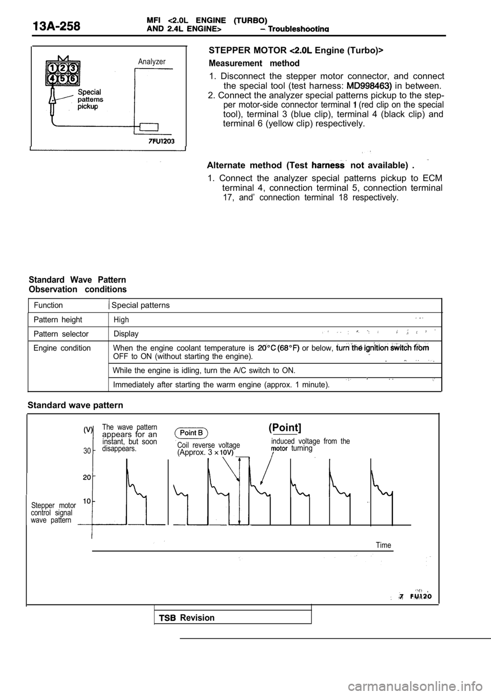
Analyzer
STEPPER MOTOR Engine (Turbo)>
Measurement method
1. Disconnect the stepper motor connector, and connect
the special tool (test harness:
in between.
2. Connect the analyzer special patterns pickup to the step-
per motor-side connector terminal (red clip on the special
tool), terminal 3 (blue clip), terminal 4 (black clip) and
terminal 6 (yellow clip) respectively.
Alternate method (Test
not available) .
1. Connect the analyzer special patterns pickup to ECM
terminal 4, connection terminal 5, connection termi nal
17, and’ connection terminal 18 respectively.
Standard Wave Pattern
Observation conditions
Function Special patterns
Pattern height
Pattern selector
Engine conditionHigh
Display
When the engine coolant temperature is or below,
OFF to ON (without starting the engine)..
While the engine is idling, turn the A/C switch to ON.. .Immediately after starting the warm engine (approx. 1 minute).
Standard wave pattern
The wave patternappears for aninstant, but soon
30disappears.
Stepper motor
10
control signal
wave pattern
Coil reverse voltage(Approx. 3
(Point]
induced voltage from the turning
Time
Revision
Page 1039 of 2103
![MITSUBISHI SPYDER 1990 Service Repair Manual AUTOMATIC TRANSAXLE ENGINE’
(TURBO) AND
ENGINE> T r o u b l e s h o o t i n g
Code No. 59 Anomalous vibration occurrence
[Comment]l Noise generatedIf pulse generator A output ind MITSUBISHI SPYDER 1990 Service Repair Manual AUTOMATIC TRANSAXLE ENGINE’
(TURBO) AND
ENGINE> T r o u b l e s h o o t i n g
Code No. 59 Anomalous vibration occurrence
[Comment]l Noise generatedIf pulse generator A output ind](/manual-img/19/57345/w960_57345-1038.png)
AUTOMATIC TRANSAXLE ENGINE’
(TURBO) AND
ENGINE> T r o u b l e s h o o t i n g
Code No. 59 Anomalous vibration occurrence
[Comment]l Noise generatedIf pulse generator A output indicates the revolutio n alteration by more than 50
l Automatic transmission fluid deteriorated in a specified cycle, diagnosis code 59 is output.
l occurred
Yes there noise in the pulse generator Eliminate the source Of A output waveform?
No
Replace automatic’transmission fluid.
Check trouble symptom.
NG
Inspection procedure 15; vibration.
(Refer to
Code Torque reduction request and execution sig-
nal lines
causeCode Torque reduction request signal lines
Code
Torque reduction execution signal lines
[Comment]l Malfunction of ECMIf a “torque reduction executing” signal is detecte d for 0.2 second or more while al Malfunction of TCM
“no torque reduction request” signal is being outpu t, there is a short-circuit in the
l Malfunction of connector
torque reduction request signal line or an open cir cuit in the torque reduction executionsignal line, and code No. 61 is output.
If a “torque reduction executing” signal is not det ected four times even though 0.2
second has passed since a “torque reduction request ” signal was output, there is
an open circuit in the torque reduction request sig nal line and code No. 62 is output.
If a “torque reduction signal is not detected under the following conditi ons,there is a short-circuit in the torque reduction execution signal line and code NO.
63 is output.
The transaxle output shaft speed has been 1,000
or higher after the ignition
switch in turned on.
Engine speed has been 1,000 or higher for 20 minutes or more after the ignitio nswitch is turned on.
TSB Revision .
Measure at ECM
lDisconnect the connector and
l
Voltage between (7) and ground
l switch.
NG
Check the l
OK
Check trouble
Repair
TCM and
u n
Replace the TCM.
Page 1050 of 2103
![MITSUBISHI SPYDER 1990 Service Repair Manual AUTOMATIC TRANSAXLE
ENGINE (TURBO) AND ENGINE> Troubleshooting
INSPECTION PROCEDURES 12
l Some points (Early, late shifting points) P r o b a b l e c a u s e
[Comment]Some shift poi MITSUBISHI SPYDER 1990 Service Repair Manual AUTOMATIC TRANSAXLE
ENGINE (TURBO) AND ENGINE> Troubleshooting
INSPECTION PROCEDURES 12
l Some points (Early, late shifting points) P r o b a b l e c a u s e
[Comment]Some shift poi](/manual-img/19/57345/w960_57345-1049.png)
AUTOMATIC TRANSAXLE
ENGINE (TURBO) AND ENGINE> Troubleshooting
INSPECTION PROCEDURES 12
l Some points (Early, late shifting points) P r o b a b l e c a u s e
[Comment]Some shift points occurs early, late while driving.
In such cases, the cause is probably al
Malfunction of valve body
defective valve body, or it is a phenomenon related control and is not an abnormality.
Refer to Automatic Transaxle Overhaul
Does fuzzy shifting occur normally? No problem because it is a phenomenon that appears due to
Nofactors associated with control.
YesDeviations at some shift points occurs only when the ATF is cold or less].
NoYes Deviations at some shift hot or more].
Valve body disassembly, cleaning and reassembly
Pay particular attention to loosening of bolts, and to damage,
If it is considered that the damage or chipping can not be
repaired, replace the valve body assembly.
INSPECTION PROCEDURE 13
lNo fail-safe codes (Does not shift)Probable cause
[Comment]l Malfunction of overdrive switch
Shifting does not occur while driving, and no fail- safe codes are output. In such cases, the l
cause is probably a defective overdrive switch or P ark/Neutral position switch.Malfunction of Park/ Neutral position switch
l Malfunction of power supply circuit
l Malfunction of TCM
No
Yes
Check to be sure that backup power is being supplie d to
the TCM.Does overdrive operate?
Yes
SCAN TOOL Data list
l 35 Overdrive switchCheck to be sure that power is being supplied to th e TCM
SCAN TOOL Data list
l 37 Park/ Neutral position switch
I OK: TCM input signal and selector lever position
should match.
Check the overdrive switch system according to insp ection
NGOK
, procedure (Refer to
Replace the TCM. ,
OK: When overdrive switch turns from OFF to ON,
scan tool display turns from OFF to ON.
Code No. 36, 37
Park/Neutral position switch system
(Refer to
Power circuit check
lPay particular attention to open circuits in the ha rness,defective connector connections and open circuits i nfuses.lIf there is an open circuit in a fuse, the cause of
the should be located and it should be
TSB Revision
Page 1059 of 2103
AUTOMATIC TRANSAXLE
ENGINE (TURBO) AND ENGINE> Troubleshooting
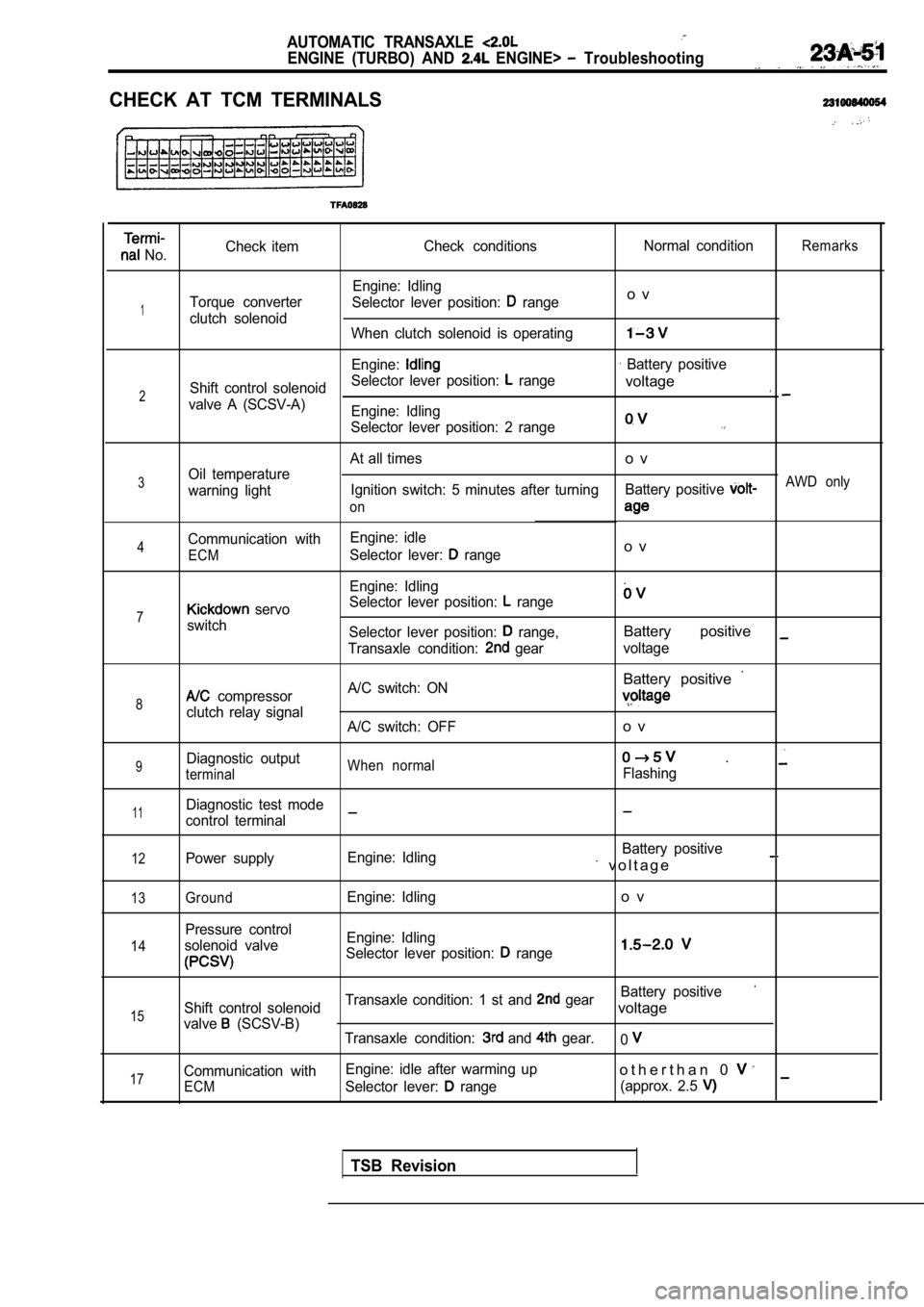
CHECK AT TCM TERMINALS
No.Check item
Check conditions Normal conditionRemarks
Engine: Idling
Torque converter Selector lever position:
rangeo v
1clutch solenoid
When clutch solenoid is operating
Engine: Battery positive
Shift control solenoid Selector lever position:
range
2voltage
valve A (SCSV-A)
Engine: Idling
Selector lever position: 2 range
At all timeso v
3Oil temperature
warning light Ignition switch: 5 minutes after turning
Battery positive AWD only
on
Communication with Engine: idle4Selector lever: rangeo vECM
Engine: Idling
Selector lever position:
range7 servo
switch Selector lever position:
range,Battery positive
Transaxle condition: gearvoltage
Battery positive
8 compressor A/C switch: ON
clutch relay signal
A/C switch: OFFo v
9Diagnostic outputWhen normal .
terminalFlashing
11Diagnostic test mode
control terminal
12Power supply Engine: Idling Battery positive v o l t a g e
13
14
15
17
GroundEngine: Idlingo v
Pressure control
solenoid valve Engine: Idling
Selector lever position:
range
Battery positive
Shift control solenoid Transaxle condition: 1 st and gearvoltage
valve (SCSV-B)
Transaxle condition: and gear.0
Communication with Engine: idle after warming upo t h e r t h a n 0
ECMSelector lever: range
(approx. 2.5
TSB Revision