1990 MITSUBISHI SPYDER ECU
[x] Cancel search: ECUPage 8 of 2103
G E N E R A L How to Use Troubleshooting/Inspection Service Points
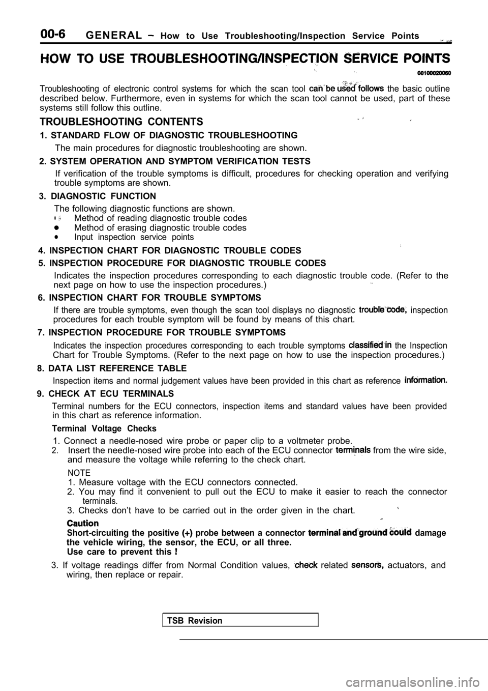
Troubleshooting of electronic control systems for which the scan tool the basic outline
described below. Furthermore, even in systems for w hich the scan tool cannot be used, part of these
systems still follow this outline.
TROUBLESHOOTING CONTENTS
1. STANDARD FLOW OF DIAGNOSTIC TROUBLESHOOTING
The main procedures for diagnostic troubleshooting are shown.
2. SYSTEM OPERATION AND SYMPTOM VERIFICATION TESTS If verification of the trouble symptoms is difficul t, procedures for checking operation and verifying
trouble symptoms are shown.
3. DIAGNOSTIC FUNCTION The following diagnostic functions are shown.
l ,Method of reading diagnostic trouble codes
Method of erasing diagnostic trouble codes
lInput inspection service points
4. INSPECTION CHART FOR DIAGNOSTIC TROUBLE CODES
5. INSPECTION PROCEDURE FOR DIAGNOSTIC TROUBLE CODE S
Indicates the inspection procedures corresponding t o each diagnostic trouble code. (Refer to the
next page on how to use the inspection procedures.)
6. INSPECTION CHART FOR TROUBLE SYMPTOMS
If there are trouble symptoms, even though the scan tool displays no diagnostic inspection
procedures for each trouble symptom will be found b y means of this chart.
7. INSPECTION PROCEDURE FOR TROUBLE SYMPTOMS
Indicates the inspection procedures corresponding t o each trouble symptoms the Inspection
Chart for Trouble Symptoms. (Refer to the next page on how to use the inspection procedures.)
8. DATA LIST REFERENCE TABLE
Inspection items and normal judgement values have b een provided in this chart as reference
9. CHECK AT ECU TERMINALS
Terminal numbers for the ECU connectors, inspection items and standard values have been provided
in this chart as reference information.
Terminal Voltage Checks
1. Connect a needle-nosed wire probe or paper clip to a voltmeter probe.
2.Insert the needle-nosed wire probe into each of the ECU connector from the wire side,
and measure the voltage while referring to the chec k chart.
NOTE
1. Measure voltage with the ECU connectors connecte d.
2. You may find it convenient to pull out the ECU t o make it easier to reach the connector
terminals.
3. Checks don’t have to be carried out in the order given in the chart.
Short-circuiting the positive probe between a connector damage
the vehicle wiring, the sensor, the ECU, or all thr ee.
Use care to prevent this
3. If voltage readings differ from Normal Condition values, related actuators, and
wiring, then replace or repair.
TSB Revision
Page 9 of 2103
GENERAL How to Use Troubleshooting/Inspection Service Points
4.After repair or replacement, recheck the voltmeter to confirm the repair
the problem.
Terminal Resistance and Continuity Checks
1. Turn the ignition switch to off.
2. Disconnect the ECU connector.
3.Measure the resistance and check for continuity bet ween the terminals of the ECU
connector while referring to the check chart.
NOTE
Checks don’t have to be carried out in the order gi ven in the chart.
Cautlon
If resistance and continuity checks are performed the wrong terminals, damage
vehicle wiring, sensors, ECU, and/or ohmmeter may o ccur.
Use care to prevent this!
4.If the ohmmeter shows any deviation from the Normal Condition value, check the corresponding
5.
sensor, actuator and related electrical wiring, then repair or replace.
After repair or replacement, recheck with the ohmme ter to confirm that the repair
the problem.
10. INSPECTION PROCEDURES USING AN OSCILLOSCOPE
When there are inspection procedures using an oscil loscope, these are listed here.
,
TSB Revision
Page 10 of 2103
GENERAL How to Use Service
HOW TO USE THE INSPECTION PROCEDURES.. ,
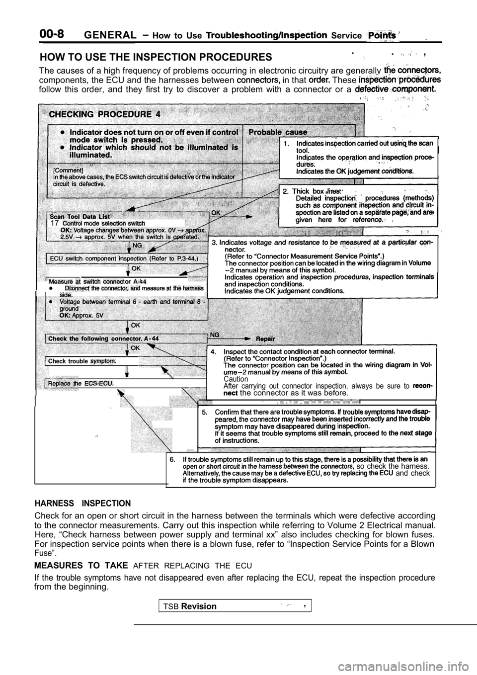
The causes of a high frequency of problems occurrin g in electronic circuitry are generally
components, the ECU and the harnesses between in that These
follow this order, and they first try to discover a problem with a connector or a
17
Check trouble
I
CautionAfter carrying out connector inspection, always be sure to the connector as it was before.
so check the harness. and check
HARNESS INSPECTION
Check for an open or short circuit in the harness b etween the terminals which were defective according
to the connector measurements. Carry out this inspe ction while referring to Volume 2 Electrical manual.
Here, “Check harness between power supply and termi nal xx” also includes checking for blown fuses.
For inspection service points when there is a blown fuse, refer to “Inspection Service Points for a Blown
Fuse”.
MEASURES TO TAKE AFTER REPLACING THE ECU
If the trouble symptoms have not disappeared even a fter replacing the ECU, repeat the inspection procedure
from the beginning.
TSBRevision
,
Page 11 of 2103

GENERAL How to Use Troubleshooting/Inspection Service ‘Points
CONNECTOR
Turn the ignition switch to when connecting and discon-
necting the connectors, and turn the ignition switch to ON
when measuring if there are no instructions to the contrary.
IF INSPECTING WITH THE CONNECTOR
CONNECTED
(WITH CIRCUIT IN A CONDITION OF
Waterproof Connectors
Be sure to use the special tool (harness connector) . Never
insert a test probe from the. harness side, because to do
so will reduce the waterproof performance and result in corro-
sion.
Ordinary (non-waterproof) Connectors
Check by inserting the test probe from’. the harness side.
Note that if the connector (control unit, etc.) is too small to
permit insertion of the test probe, it should not b e forced;
use a special tool (the extra-thin probe in the har ness set
for checking) for this purpose.
IF INSPECTING WITH THE CONNECTOR DISCONNECTED,
Use the special tool (inspection harness for
pin
contact pressure in the harness set, for ‘inspectio n).
The inspection harness for connector pin contact pr essure’
should be used. The test probe
be forcibly in-
serted, as it may cause a defective contact.
Caution. .
At time, be careful not to short the connector
with the test probes. To do so may damage the
inside the ECU.
Revision
Page 22 of 2103
GENERAL before Service
PRECAUTIONS BEFORE SERVICE.
SUPPLEMENTAL RESTRAINT SYSTEM
1. to follow when servicing SRS
(1) Be sure to read GROUP Supplemental Restraint System
For safe operations, please follow the directions a nd heed all
(2) Always use the designated special tools and tes t equipment.
(3) Wait at least 60 seconds after disconnecting the battery cable before” further work;
The SRS system is designed to retain enough voltage to deploy the air bag even after the battery
has been disconnected. Serious injury may result from unintended air bag deployment if work
is done on the SRS system immediately after the bat tery cable is disconnected.
(4) Never attempt to disassemble or repair the SRS components (SRS-ECU air bag module and
clock spring). If faulty, replace it.
(5) Warning labels must be heeded when servicing or handling SRS components. Warning labels
are located in the following locations.
Sun visor
l Glove box
. S R S - E C U
l Steering wheel
l Air bag module
l Clock spring
l Steering gear and linkage clamp
(6) Store components removed from the SRS
a clean and dry place.
The air bag module should be stored on a flat surfa ce and placed so that the pad surface is’
facing upward.
Do not place anything on top of it.
(7) Be sure to deploy the air bag before disposing of the air bag’module or disposing of a vehicle
equipped with an air bag. (Refer to GROUP
Air Bag Module Disposal Procedures.)
(8) Whenever you finish servicing the
check the SRS warning light operation to make sure
that the system functions properly.
2.Observe the following when carrying out operations on places where SRS components are installed,’
.,
including operations not directly related to the SR S air bag.
(1) When removing or installing parts do not allow any impact or shock to the SRS components.
(2) SRS components should not be subjected to heat over so remove the SRS compo-
nents before drying or baking the vehicle after painting.
After re-installing them, check the SRS warning lig ht operation to make sure that the system
functions properly.
SERVICING THE ELECTRICAL SYSTEM
1. Note the following before proceeding with work o n the
electrical system.
Note that the following must never be done:
Unauthorized modifications of any electrical device or
wiring, because such modifications might lead to a vehicle
malfunction, over-capacity or short-circuit that co uld result
in a fire in the vehicle.
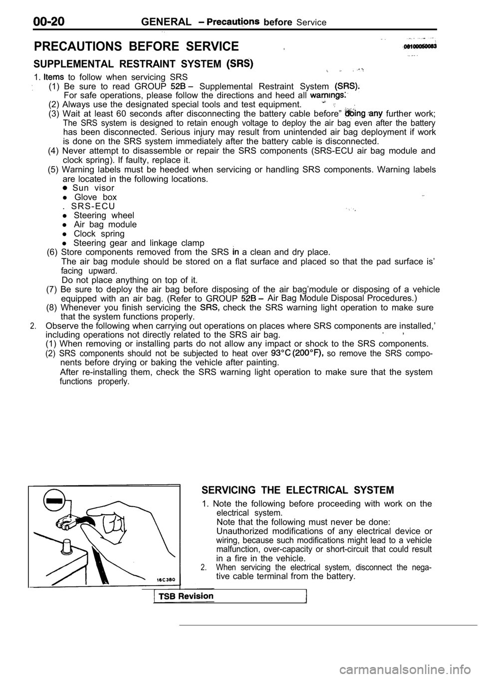
2.When servicing the electrical system, disconnect th e nega-
tive cable terminal from the battery.
Page 24 of 2103
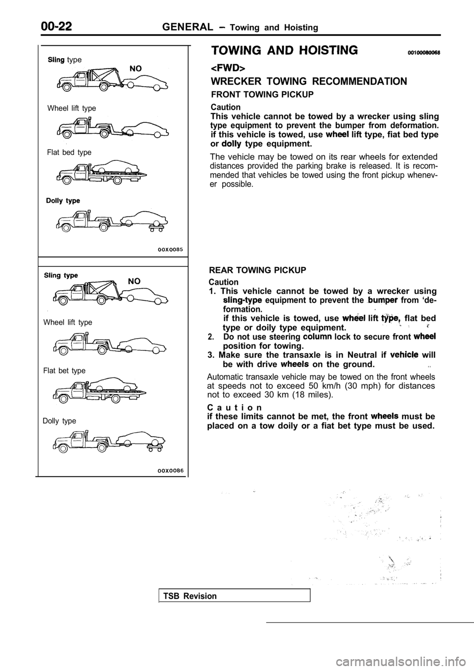
GENERAL Towing and Hoisting
type
Wheel lift type
Flat bed type
Wheel lift type
Flat bet type
Dolly type
WRECKER TOWING RECOMMENDATION
FRONT TOWING PICKUP
Caution
This vehicle cannot be towed by a wrecker using sli ng
type equipment to prevent the bumper from deformati on.
if this vehicle is towed, use lift type, fiat bed type
or
type equipment.
The vehicle may be towed on its rear wheels for ext ended
distances provided the parking brake is released. It is recom-
mended that vehicles be towed using the front picku p whenev-
er possible.
REAR TOWING PICKUP
Caution
1. This vehicle cannot be towed by a wrecker using
equipment to prevent the from ‘de-
formation.
if this vehicle is towed, use lift flat bed
type or doily type equipment.
2.Do not use steering lock to secure front
position for towing.
3. Make sure the transaxle is in Neutral if
will
be with drive
on the ground.. .
Automatic transaxle vehicle may be towed on the fro nt wheels
at speeds not to exceed 50 km/h (30 mph) for distan ces
not to exceed 30 km (18 miles).
C a u t i o n
if these limits cannot be met, the front
must be
placed on a tow doily or a fiat bet type must be us ed.
TSB Revision
Page 25 of 2103
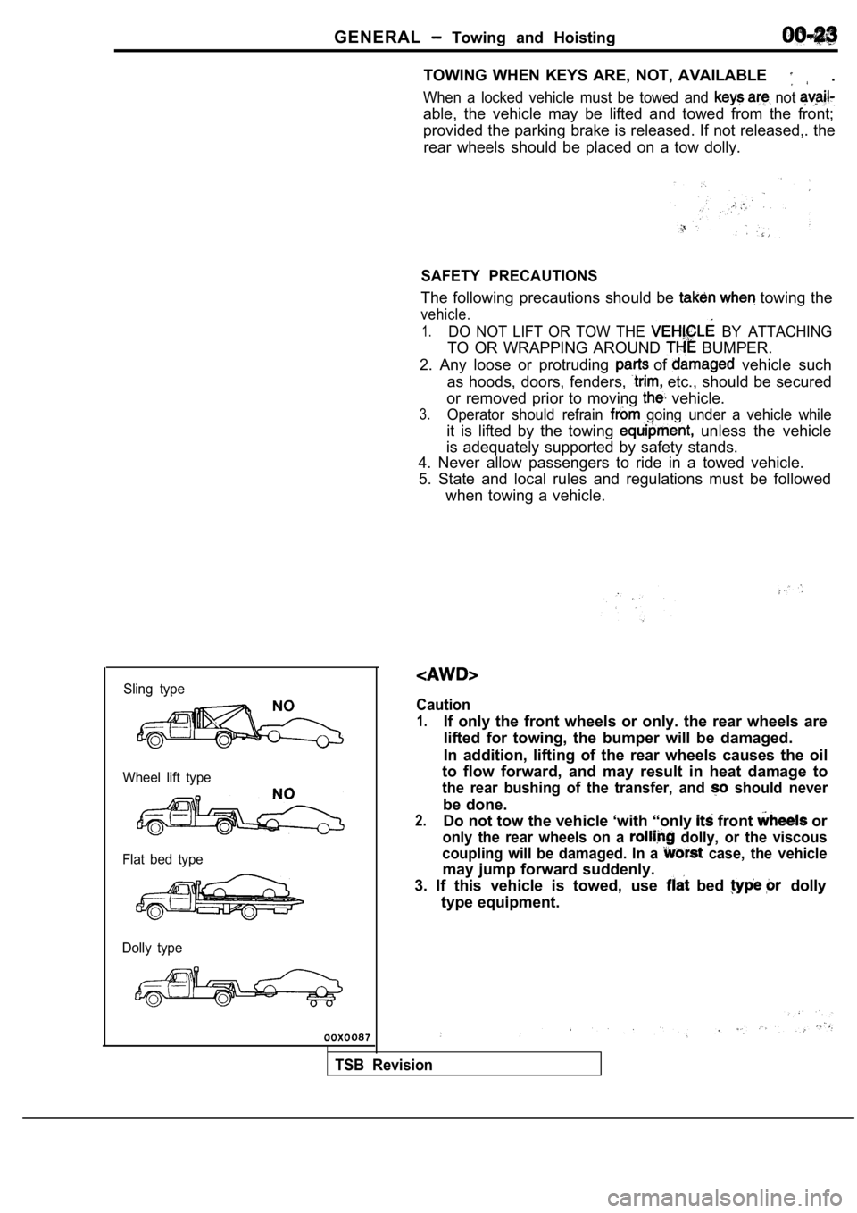
GENERAL Towing and Hoisting
Sling type
Wheel lift type
Flat bed type
Dolly type
TOWING WHEN KEYS ARE, NOT, AVAILABLE .
When a locked vehicle must be towed and not
able, the vehicle may be lifted and towed from the front;
provided the parking brake is released. If not rele ased,. the
rear wheels should be placed on a tow dolly.
SAFETY PRECAUTIONS
The following precautions should be towing the
vehicle.
1.DO NOT LIFT OR TOW THE BY ATTACHING
TO OR WRAPPING AROUND BUMPER.
2. Any loose or protruding
of vehicle such
as hoods, doors, fenders,
etc., should be secured
or removed prior to moving
vehicle.
3.Operator should refrain going under a vehicle while
it is lifted by the towing unless the vehicle
is adequately supported by safety stands.
4. Never allow passengers to ride in a towed vehicl e.
5. State and local rules and regulations must be fo llowed
when towing a vehicle.
Caution
1.If only the front wheels or only. the rear wheels a re
lifted for towing, the bumper will be damaged.
In addition, lifting of the rear wheels causes the oil
to flow forward, and may result in heat damage to
the rear bushing of the transfer, and should never
be done.
2.Do not tow the vehicle ‘with “only front or
only the rear wheels on a dolly, or the viscous
coupling will be damaged. In a
case, the vehicle
may jump forward suddenly.
3. If this vehicle is towed, use
bed dolly
type equipment.
TSB Revision
Page 51 of 2103
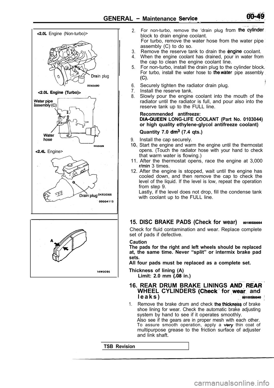
GENERAL Maintenance
a
Engine (Non-turbo)>
in plug
Engine>
2.For non-turbo, remove the ‘drain plug from
block to drain engine coolant.
For turbo, remove the water hose from the water pip e
assembly (C) to do so.
3.
4.
5.Remove the reserve tank to drain the coolant.
When the engine coolant has drained, pour in water from
the cap to clean the engine coolant line.
For non-turbo, install the drain plug to the cylind er block.
For turbo, install the water hose to pipe assembly
6.
7.
8.
Securely tighten the radiator drain plug.
Install the reserve tank.
9.
Slowly pour the engine coolant into the mouth of th e
radiator until the radiator is full, and pour also into the
reserve tank up to the FULL line.
Recommended antifreeze:
LONG-LIFE COOLANT (Part No. 0103044)
or high quality ethylene-glycol antifreeze coolant)
Quantity 7.0
(7.4 qts.)
Install the cap securely.
Start the engine and warm the engine until the the rmostat
opens. (Touch the radiator hose with your hand to c heck
that warm water is flowing.)
11. After the thermostat opens, race the engine at 3,000
3 times.
12. After the engine is stopped, wait until the eng ine has
cooled down, and then remove the cap to check the
level of the liquid. If the level is low, repeat th e operation
from step 9.
Lastly, if the level does not drop, fill the conden se tank
with coolant up to the FULL line.
15. DISC BRAKE PADS (Check for wear)
Check for fluid contamination and wear. Replace com plete
set of pads if defective.
Caution
The pads for the right and left wheels should be re placed
at, the same time. Never “split” or intermix brake pad
sets.
All four pads must be replaced as a complete set.
Thickness of lining (A) Limit: 2.0 mm
in.)
16. REAR DRUM BRAKE LININGS
WHEEL CYLINDERS for and
l e a k s )
1.Remove the brake drum and check of brake
shoe lining for wear. Check the automatic brake adj usting
system by hand to see if it operates smoothly.
Also see if the gears are in proper mesh with each other.
To assure smooth operation, apply a thin coat of
multipurpose grease to the friction surface of adju ster
and link shaft.
TSB Revision