Page 54 of 2103
GENERAL Maintenance Service
0 0 0 0 0 1 6 7
Inflator case
CHECK
Check SRS-ECU case and brackets for dents, cracks,
deformities or rust.
Caution
The SRS may not activate if a front impact sensor
not installed properly, which could result serious injury
or death to the driver and ,
AIR BAG MODULE, STEERING
CLOCK
SPRING CHECK
1. Remove the air bag module,
and clock
spring. (Refer to GROUP
and
Clock Spring.)
Caution
The removed air bag be In a
clean, dry place with the pad cover face up.
2. Check pad cover for dents, cracks of deformities .
3.Check connector for damage, terminals deformities, and
harness for binds.
4.Check air bag inflator case for dents, cracks or deformities.
5.Check harness (built into steering wheel) and conne ctors
for damage, and terminals for deformities.
Page 90 of 2103
11ENGINE Crankshaft pear Oil
,
BOLT PLATE BOLT
R E M O V A L
Use the special tool to secure. the
or drive plate,
and remove the bolt.
INSTALLATION SERVICE
CRANKSHAFT REAR OIL SEAL INSTALLATION
(1) Apply a small amount of engine oil to the entir e inside
diameter of the oil seal lip.
(2) Tap in the oil seal as shown in the illustratio n.
PLATE BOLT BOLT
(1) Clean off all sealant, oil and other substances which are
adhering to the threaded bolts, crankshaft thread h oles
and the flywheel
or drive plate
(2) Apply oil to the bearing surface of the flywhee l
or drive plate bolt.
(3) Apply oil to the crankshaft thread holes.
(4) Apply sealant to the threaded mounting bolts.
Specified sealant:
Stud locking 4170 or equivalent
TSB Revision
(5) Use the special tool to secure the flywheel or
drive plate and then tighten the the speci-
fied torque.
Specified torque:
Nm
Page 122 of 2103

ENGINE OVERHAUL Timing’
COUNTERBALANCE SHAFT
INSTALLATION
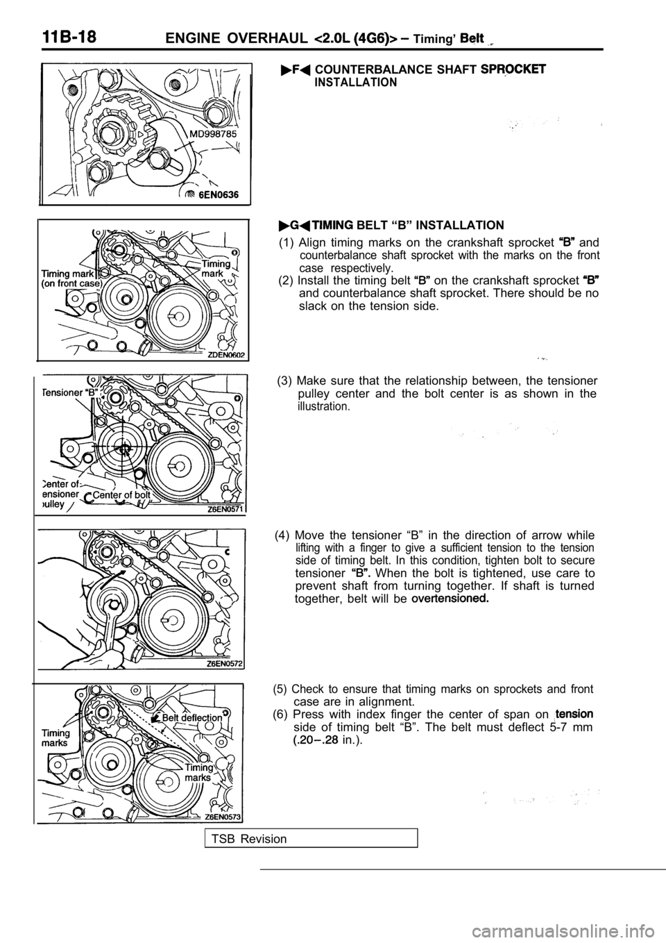
BELT “B” INSTALLATION
(1) Align timing marks on the crankshaft sprocket
and
counterbalance shaft sprocket with the marks on the front
case respectively.
(2) Install the timing belt on the crankshaft sprocket
and counterbalance shaft sprocket. There should be no
slack on the tension side.
(3) Make sure that the relationship between, the te nsioner
pulley center and the bolt center is as shown in th e
illustration.
(4) Move the tensioner “B” in the direction of arrow while
lifting with a finger to give a sufficient tension to the tension
side of timing belt. In this condition, tighten bolt to secure
tensioner When the bolt is tightened, use care to
prevent shaft from turning together. If shaft is tu rned
together, belt will be
(5) Check to ensure that timing marks on sprockets and front
case are in alignment.
(6) Press with index finger the center of span on
side of timing belt “B”. The belt must deflect 5-7 mm
in.).
TSB Revision
Page 151 of 2103
Front Case,, ENGINE OVERHAUL Shaft and ‘Pan
Phillips screwdriver
B O L T ,
(1) Phillips screwdriver hole in the left side
of the cylinder block to lock the counterbalance sh aft.
(2) Secure the oil pump driven gear onto the left c ounterbal-
ance shaft by tightening the flange bolt to specified torque.
PLUG INSTALLATION
(1) Install a new O-ring to the front case.
(2)Using the special tool, install the plug and tighten to speci-
fied torque.
TSB Revision
Page 214 of 2103

ENGINE OVERHAUL
FORM-IN-PLACE GASKETS
There are numerous places where form-in-place gaskets are used on the engine. Care must be
when applying form-in-place gaskets to assure obtaining the desired results. size, continuity, ‘and
location are of great importance. Too thin a bead can result in leakage
too much can result’ in
spill-over which can break off and obstruct fluid f eed lines.
A continuous bead of the proper width
essential to obtain a leak-free joint.
GASKET DISASSEMBLY
Parts assembled with form-in-place gaskets may be d isassembled without unusual effort’
it may be necessary to lightly tap the part with a mallet or other suitable tool to break the seal between
the mating surfaces.A flat gasket scraper may also be lightly tapped in to the joint but care be
taken not to damage the mating surfaces.
SURFACE PREPARATION
Scrape clean or wire brush all gasketsurfaces removing all loose material. Inspect
assure gasket rails are flat.
Flatten rails with a hammer on a flat plate if
must be free of oil and dirt. Make sure old gasket material is removed from blind
FORM-IN-PLACE GASKET APPLICATION
Assembling parts using a form-in-place gasket requires care but it’s easier than using precut gaskets.
Gasket material should be applied sparingly 1 mm
inch.) diameter or less to one
surface, Be certain the material surrounds each mou nting hole.
Excess material can easily be
‘off. Components should be torqued in place within 15 minutes. The use of a locating dowel is recommen ded
during assembly, to prevent smearing the material off location.
Loctite 18718 gasket material or equivalent should be applied in a continuous bead
3
mm
inch.) in diameter. All mounting holes must be circled.
For corner sealing, 3.17 or 6.35
mm
or inch.) drop is placed in the center of the gasket contact area. Uncured may
be removed with a shop towels. Components should be torqued in place while the sea lant
wet
to the touch (within 10 minutes). The usage of a locating dowel is recommended during assembly to
prevent smearing of material off location.
MOPAR TORQUE CURE GASKET MAKER
Mopar torque cure gasket maker is a unique anaerobi c type gasket material to be used ONLY
the and engine block. The material cures in the absenc e of air when. two
metallic surfaces. It will not cure if left in the uncovered tube. This anaerobic material
specially made
to seal the area between the
and cylinder block without disturbing the bearing’ or
alignment of these components.. .
TSB Revision
Page 296 of 2103
INSTALLATION SERVICE POINTS
CRANKSHAFT REAR OIL SEAL INSTALLATION
(1) Apply a small amount of engine oil to the entir e inside
diameter of the oil seal lip.
(2) Tap in the oil seal as shown in the illustratio n.
DRIVE PLATE BOLT BOLT
INSTALLATION
(1) Clean off all sealant, oil and other substances which are
adhering to the threaded bolts, crankshaft thread h oles
and the flywheel
or drive plate
(2) Apply oil to the bearing surface of the flywhee l
or drive plate bolt.
(3) Apply oil to the crankshaft thread holes.
(4) Apply sealant to the threaded mounting bolts.
Specified sealant:
Stud locking 4170 or equivalent
(5) Use the special tool to secure the
or
drive plate and then tighten the bolts to the speci-
fied torque. .
Specified torque: 127-137 Nm
TSB Revision
Page 327 of 2103

ENGINE OVERHAUL Timing Belt
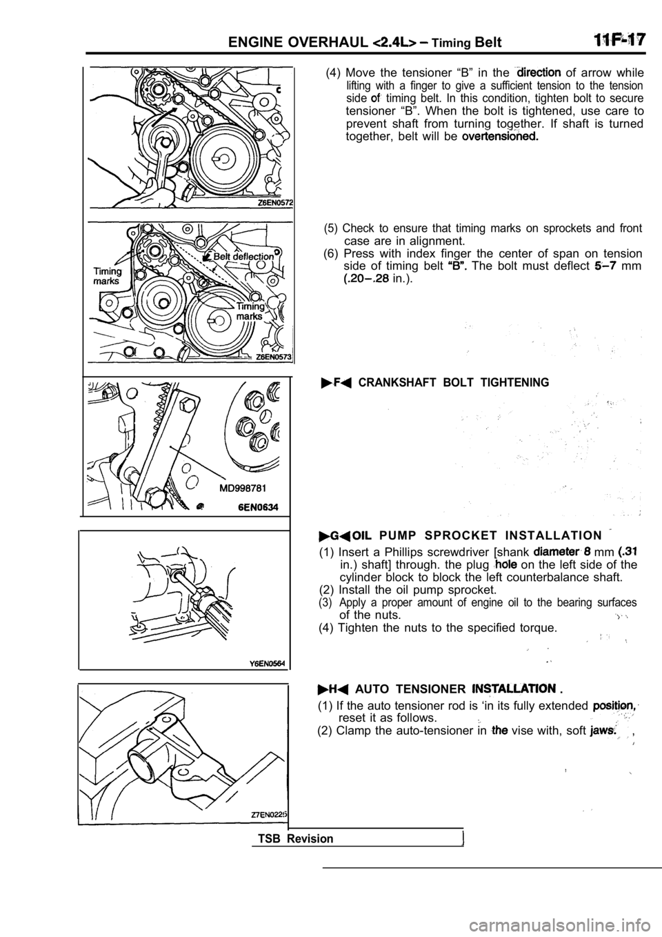
(4) Move the tensioner “B” in the of arrow while
lifting with a finger to give a sufficient tension to the tension
side timing belt. In this condition, tighten bolt to secure
tensioner “B”. When the bolt is tightened, use care to
prevent shaft from turning together. If shaft is tu rned
together, belt will be
(5) Check to ensure that timing marks on sprockets and front
case are in alignment.
(6) Press with index finger the center of span on t ension
side of timing belt
The bolt must deflect mm
in.).
CRANKSHAFT BOLT TIGHTENING
P U M P S P R O C K E T I N S T A L L A T I O N
(1) Insert a Phillips screwdriver [shank mm
in.) shaft] through. the plug on the left side of the
cylinder block to block the left counterbalance sha ft.
(2) Install the oil pump sprocket.
(3) Apply a proper amount of engine oil to the beari ng surfaces
of the nuts.
(4) Tighten the nuts to the specified torque.
AUTO TENSIONER .
(1) If the auto tensioner rod is ‘in its fully exte nded
reset it as follows.
(2) Clamp the auto-tensioner in vise with, soft ,
TSB Revision
Page 340 of 2103

ENGINE OVERHAUL Rocker Arms and Camshaft
R E M O V A L S E R V I C E
ARMS AND ARM
REMOVAL.
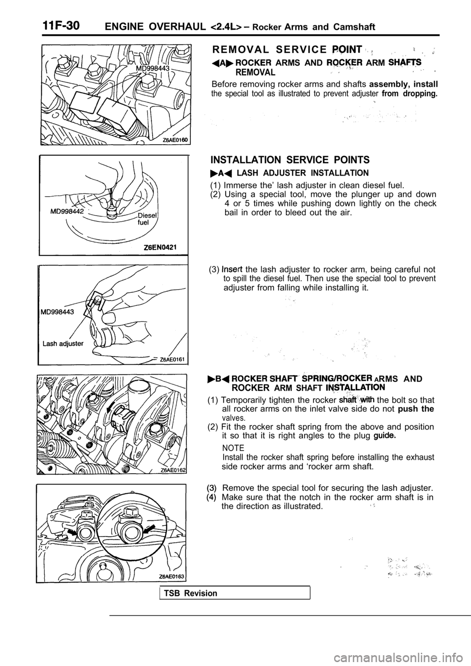
Before removing rocker arms and shafts assembly, install
the special tool as illustrated to prevent adjuster from dropping.
INSTALLATION SERVICE POINTS
LASH ADJUSTER INSTALLATION
(1) Immerse the’ lash adjuster in clean diesel fuel .
(2) Using a special tool, move the plunger up and d own
4 or 5 times while pushing down lightly on the chec k
bail in order to bleed out the air.
(3)
the lash adjuster to rocker arm, being careful not
to spill the diesel fuel. Then use the special tool to prevent
adjuster from falling while installing it.
ARMS AND
ROCKERARM SHAFT
(1) Temporarily tighten the rocker the bolt so that
all rocker arms on the inlet valve side do not push the
valves.
(2) Fit the rocker shaft spring from the above and position
it so that it is right angles to the plug
NOTE
Install the rocker shaft spring before installing t he exhaust
side rocker arms and ‘rocker arm shaft.
Remove the special tool for securing the lash adjus ter.
Make sure that the notch in the rocker arm shaft is in
the direction as illustrated.
TSB Revision