Page 803 of 2103
Engine
Engine>
intake air
To combustion
chamber
G: Green
Yellow
White
Throttle body
Fuel pressure
regulator
Redpaintmark
EVAP purge
(ON: open)
EVAP canister
EGR(ON: closed)
EGR
VACUUM HOSE CHECK
Using the VACUUM HOSE ROUTING as a guide, check tha t
the vacuum hoses are correctly connected, and that there
are no bends or damage to the hoses.
VACUUM HOSE INSTALLATION
1.When connecting the vacuum hoses, they be securely
inserted onto the nipples.
2.To connect the hoses correctly, use the VACUUM HOSE ROUT-
ING as a guide.
TSB Revision
Page 867 of 2103

MANUAL TRANSAXLE
ENGINE (TURBO) AND ENGINE>
TRANSAXLE CONTROL
REMOVAL AND INSTALLATION
Caution: SRSBe careful not to subject the SRS-ECU to anyshocks during removal and installation of thetransaxle control cable and shift lever assembly.
Engine>
3.9 Nm
2.9
Engine (Turbo)>
9
9
9 bs.
.
NOTE Resin clip positionTransaxle control cable assemblyremoval steps
1. Air cleaner and air intake hose
assembly2. lever knob3. Center panel
4. Cupholder assembly
5. Floor console assembly
6. Shift lever cover
7. Console side cover
8. Nut 9. Clip (passenger compartment side)
10. Clip (transaxle side
11. Shift cable and select cable con- nection (passenger compartment
12. and select cable con-
nection (transaxle side)
13. Shift cable and select cable as-
sembly Shift lever
assembly removal steps
2 . S h i f t 3. Center. 4. assembly
5. Floor console assembly
6. Shift lever panel
7. Console side cover
9. Clip(passenger compartment side)
11. Shift cable and select cable con-nection (passenger compartmentside)14. Shift lever 15. Distance piece 16. Bushing
TSB Revision
Page 876 of 2103

MANUAL TRANSAXLE
ENGINE AND ENGINE> Transaxle Assembly
I -
Cord
I’ --
Nut
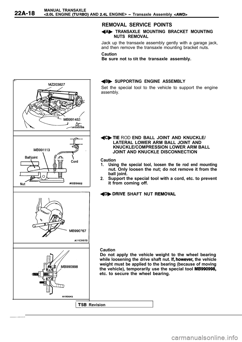
REMOVAL SERVICE POINTS
TRANSAXLE MOUNTING BRACKET MOUNTINGNUTS REMOVAL
Jack up the transaxle assembly gently with a garage jack,
and then remove the transaxle mounting bracket nuts .
Caution
Be sure not to tilt the transaxle assembly.
SUPPORTING ENGINE ASSEMBLY
Set the special tool to the vehicle to support the engine
assembly.
ROD END BALL JOINT AND KNUCKLE/
LATERAL LOWER ARM BALL JOINT AND
KNUCKLE/COMPRESSION LOWER ARM BALL
JOINT AND KNUCKLE DISCONNECTION
Caution
1.Using the special tool, loosen the tie rod end moun ting
nut. Only loosen the nut; do not remove it from the
ball joint.
2.Support the special tool with a cord, etc. to preve nt
it from coming off.
SHAFT NUT
Caution
Do not apply the vehicle weight to the wheel bearin g
while loosening the drive shaft nut. the vehicle
weight must be applied to the bearing (because of m oving
the vehicle), temporarily use the special tool
etc. to secure the wheel bearing.
I Revision
Page 878 of 2103

MANUAL TRANSAXLE
ENGINE (TURBO) AND ENGINE> Transaxle Assembly
TransaxlemountTransaxle side
s t o p p e r ,ArrowTransaxlemount
Frontstopperbracket
member
Revision
Washer
196-255 Nm
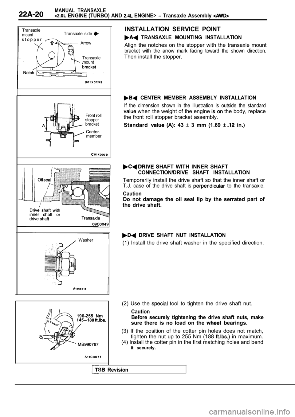
INSTALLATION SERVICE POINT
TRANSAXLE MOUNTING INSTALLATION
Align the notches on the stopper with the transaxle mount
bracket with the arrow mark facing toward the shown direction.
Then install the stopper.
CENTER MEMBER ASSEMBLY INSTALLATION
If the dimension shown in the illustration is outside the standard
when the weight of the engine the body, replace
the front roll stopper bracket assembly.
Standard
(A): 43 3 mm (1.69 in.)
SHAFT WITH INNER SHAFT
CONNECTION/DRIVE SHAFT INSTALLATION
Temporarily install the drive shaft so that the inn er shaft or
T.J. case of the drive shaft is to the transaxle.
Caution
Do not damage the oil seal lip by the serrated part of
the drive shaft.
DRIVE SHAFT NUT INSTALLATION
(1) Install the drive shaft washer in the specified direction.
(2) Use the
tool to tighten the drive shaft nut.
Caution Before securely tightening the drive shaft nuts, ma ke
sure there is no load on the bearings.
(3) If the position of the cotter pin holes does no t match,
tighten the nut up to 255 Nm (188
in maximum.
(4) Install the cotter pin in the first matching ho les and bend
it securely.
Page 924 of 2103

MANUAL TRANSAXLE OVERHAUL
Transaxle.,
22200056
0123
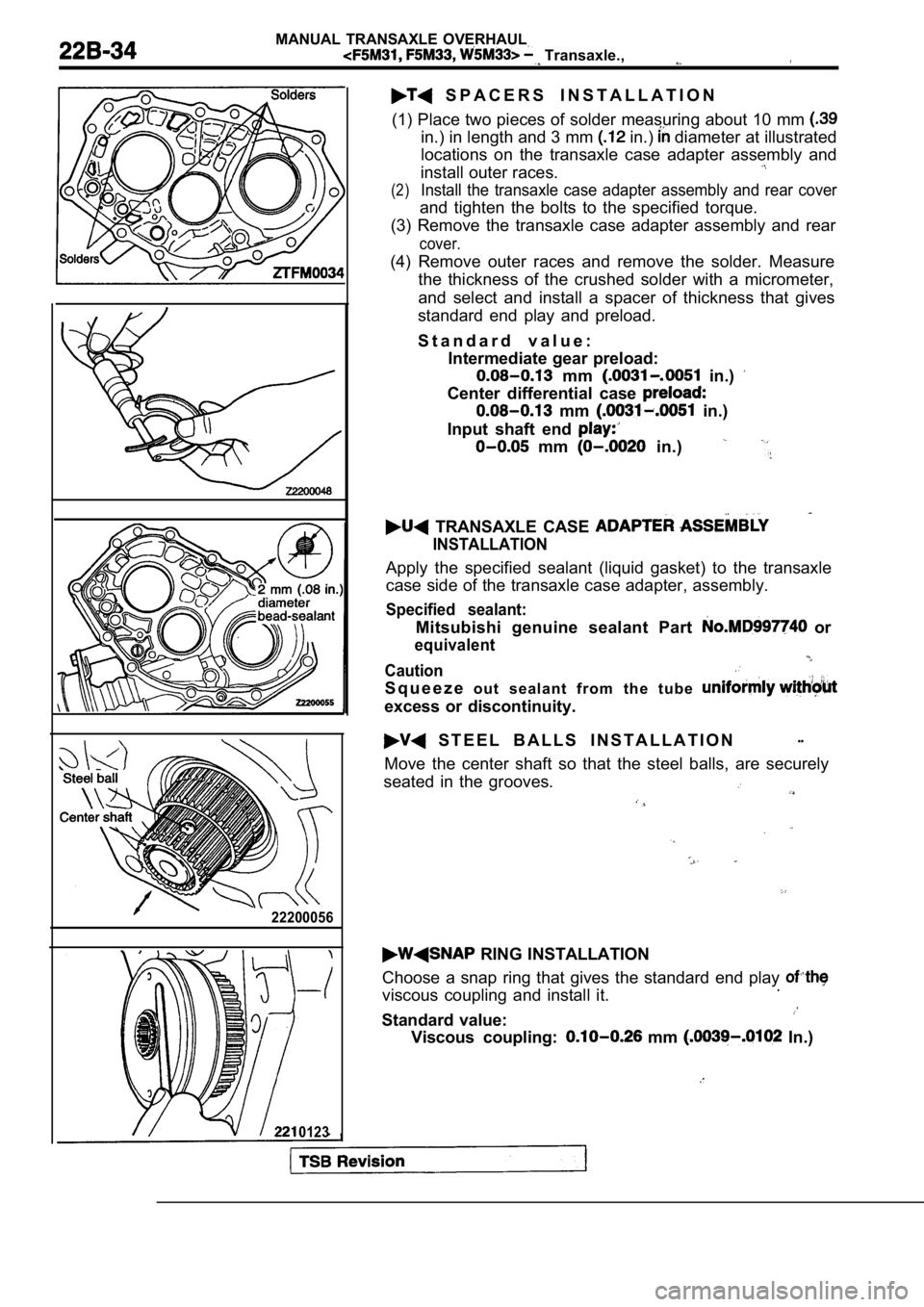
S P A C E R S I N S T A L L A T I O N
(1) Place two pieces of solder measuring about 10 m m
in.) in length and 3 mm in.) diameter at illustrated
locations on the transaxle case adapter assembly an d
install outer races.
(2)Install the transaxle case adapter assembly and rea r cover
and tighten the bolts to the specified torque.
(3) Remove the transaxle case adapter assembly and rear
cover.
(4) Remove outer races and remove the solder. Measu re
the thickness of the crushed solder with a micromet er,
and select and install a spacer of thickness that g ives
standard end play and preload.
S t a n d a r d v a l u e : Intermediate gear preload:
mm in.)
Center differential case
mm in.)
Input shaft end
mm in.)
TRANSAXLE CASE
INSTALLATION
Apply the specified sealant (liquid gasket) to the transaxle
case side of the transaxle case adapter, assembly.
Specified sealant:
Mitsubishi genuine sealant Part or
equivalent
Caution
S q u e e z e o u t s e a l a n t f r o m t h e t u b e
excess or discontinuity.
S T E E L B A L L S I N S T A L L A T I O N--
Move the center shaft so that the steel balls, are securely
seated in the grooves.
RING INSTALLATION
Choose a snap ring that gives the standard end play
viscous coupling and install it..
Standard value:
Viscous coupling: mm In.)
Page 1009 of 2103

CONTENTS
AUTOMATIC TRANSAXLE
ENGINE (NON-TURBO)> . . . . . 115
AUTOMATIC TRANSAXLE KEY INTERLOCK
AND SHIFT LOCK MECHANISMS* . . . . . . . . 192
GENERAL INFORMATION
. . . . . . . . . . . . . . . . 115
LUBRICANTS. . . . . . . . . . . . . . . . . . . . . . . . . . . .117
ON-VEHICLE SERVICE . . . . . . . . . . . . . . . . . . . 159
Automatic Transaxle Control Component
Oil Temperature Sensor Continuity Check . . . . 160
Pinion Factor Writing Procedure After
TCM Replacement or Tire Size Change
. . . 159
Selector Level Operation Check . . . . . . . . . . . . . . ,166
Shift Lock Mechanism Check. . . . . . . . . . . . . . .
1 8 6
TCM Resetting Procedure . . . . . . . . . . . . .
..159
Torque Converter Stall Testing. . . . . . . . . . . . . .166
Transaxle Fluid Level Check . . . . . . . . . . .. . .159
Transaxle Fluid Replacement. . . . . . . . . . . . . . .
Transaxle Range Sensor Continuity . . .
Check. . . . . . . . . . . . . . . . . . . . . . . . . . . . . . . . . . . .163SERVICE SPECIFICATIONS.. . . .. . .Automatic Transaxle Control Component Layout
. . . . . . . . . . . . . . . . . . . . . . . . . . . . . . . . . . . . . . . . . . .
161SPECIAL TOOLS. . . . . . . . . . . . . . . . . . . . . . . . .117Clutch Air Pressure Tests . . . . . . . . . . . . . . . . . . .168
Fluid Leakage-Torque Converter Housing Area
Check. . . . . . . . . . . . . . . . . . . . . . . . . . . . . . . . . . . .169
Hydraulic Pressure Tests. . . . . . . . . . . . . . . . . . .169
Hydraulic Circuit. . . . . . . . . . . . . . . . . . . . . . . . . . .173
TRANSAXLE ASSEMBLY. . . . . . . . . . . . . . . .
TRANSAXLE CONTROL*. . . . . . . . . . . . . . . . .187
Selector Lever Assembly. . . . . . . . . . . . . . . . . . .189
Key Interlock Mechanism Check . . . . . . . . . . .
. 186CONTINUED ON NEXT PAGE
WARNINGS REGARDING SERVICING OF SUPPLEMENTAL EQUIPPED VEHICLES
WARNING! (1) Improper service or maintenance of any componen t of the
or any component, can lead to personal
injuryordeath inadvertent the inoperative).
(2) Service or maintenance of any component or SRS-related component must be perform ed only at an authorized
MITSUBISHI dealer.
(3)MITSUBISHI dealer personnel must thoroughly review this manual, and especially its GROUP Supplemental Re-
straint System (SRS) and GROUP 00 -Maintenance Serv ice before beginning any service or maintenance of any com-
ponent of the
or any component.
NOTEThe SRS includes the following components: SRS-ECU, SRS warning light, air bag module, clockspring and inte rconnecting wiring.Other SRS-related components (that may have to be removed/installed in connection with SRS service or maintenance) are indi-cated in the table of contents by an asterisk
Page 1028 of 2103
CodeDiagnostic item.
63 Torque reduction execution signal linesShort circuit
Page 1039 of 2103
![MITSUBISHI SPYDER 1990 Service Repair Manual AUTOMATIC TRANSAXLE ENGINE’
(TURBO) AND
ENGINE> T r o u b l e s h o o t i n g
Code No. 59 Anomalous vibration occurrence
[Comment]l Noise generatedIf pulse generator A output ind MITSUBISHI SPYDER 1990 Service Repair Manual AUTOMATIC TRANSAXLE ENGINE’
(TURBO) AND
ENGINE> T r o u b l e s h o o t i n g
Code No. 59 Anomalous vibration occurrence
[Comment]l Noise generatedIf pulse generator A output ind](/manual-img/19/57345/w960_57345-1038.png)
AUTOMATIC TRANSAXLE ENGINE’
(TURBO) AND
ENGINE> T r o u b l e s h o o t i n g
Code No. 59 Anomalous vibration occurrence
[Comment]l Noise generatedIf pulse generator A output indicates the revolutio n alteration by more than 50
l Automatic transmission fluid deteriorated in a specified cycle, diagnosis code 59 is output.
l occurred
Yes there noise in the pulse generator Eliminate the source Of A output waveform?
No
Replace automatic’transmission fluid.
Check trouble symptom.
NG
Inspection procedure 15; vibration.
(Refer to
Code Torque reduction request and execution sig-
nal lines
causeCode Torque reduction request signal lines
Code
Torque reduction execution signal lines
[Comment]l Malfunction of ECMIf a “torque reduction executing” signal is detecte d for 0.2 second or more while al Malfunction of TCM
“no torque reduction request” signal is being outpu t, there is a short-circuit in the
l Malfunction of connector
torque reduction request signal line or an open cir cuit in the torque reduction executionsignal line, and code No. 61 is output.
If a “torque reduction executing” signal is not det ected four times even though 0.2
second has passed since a “torque reduction request ” signal was output, there is
an open circuit in the torque reduction request sig nal line and code No. 62 is output.
If a “torque reduction signal is not detected under the following conditi ons,there is a short-circuit in the torque reduction execution signal line and code NO.
63 is output.
The transaxle output shaft speed has been 1,000
or higher after the ignition
switch in turned on.
Engine speed has been 1,000 or higher for 20 minutes or more after the ignitio nswitch is turned on.
TSB Revision .
Measure at ECM
lDisconnect the connector and
l
Voltage between (7) and ground
l switch.
NG
Check the l
OK
Check trouble
Repair
TCM and
u n
Replace the TCM.