Page 1251 of 2103
AUTOMATIC
(e) Fit the special tool (outer) to ffie
Turn the outer cylinder clockwise and the inner
counterclockwise to unlock the lock nut and the special’
tool (inner).
Caution
When unlocking is carried force
t o b o t h
l o o s e n ,
(9Tighten the lock nut by hand the piston.
Then, use torque wrench to the lock nut to’
the specified torque.
Tightening torque: 29 Nm
Caution
The lock nut may turn adjusting rod if
tightened quickly with
or torque
wrench.
(g)Remove the special tool for securing the piston. In stall
the plug to the Low/Reverse pressure outlet and tig ht-
en to the specified torque.
a new D-ring in the servo
the switch into the case and secure it the snap ring.
the park/neutral position and manual control
lever and tighten the manual. control’ nut to the
specified torque.
,
TSB Revision
Page 1282 of 2103
AUTO T R A N S A X L E
OVER
2 1 7 5 0 3 3 3
REASSEMBLY SERVICE POINTS
STOPPER PLATE N-D PLATE TEFLON BALL
STEEL BALL LOCATION
VALVE BODY SUB ASSEMBLY
INSTALLATION
Mount the special tools, and secure the upper separating
plate and intermediate plate with the eight mountin g bolts.
Then, demount the special tools.
I
STEEL BALL RELIEF SPRING
VALVE BODY SUB ASSEMBLY
INSTALLATION
(1) Mount the special tools on the intermediate plate.
Install the separating plate.
TSB Revision
Page 1283 of 2103
solenoid
AUTOMATIC TRANSAXLE
OVERHAUL Valve Body.
(3)Secure the lower valvebody with the bolts. Then,
the special tools.
SOLENOID VALVE ASSEMBLY INSTALLATION
Install each solenoid valve in the position shown in the figure.
Solenoid valveWiringcolor
Shift control solenoid valve “A”
Orange
(SCSV-A)
Shift control solenoid valve Yellow
(SCSV-B)
Torque converter clutch
(TCC solenoid)
Pressure control solenoid Red/Black
valve (PCSV)
TSB Revision
Page 1327 of 2103
.
the servo by
Fit the claw of the the
piston to prevent. the
from use
adapter to secure it
at
Caution
1. Do not push with
2.When the
case, do not
en by hand. .,
(b) Loosen the lock nut until it is about to reach the
V-groove in the adjusting rod. Tighten the special
tool (inner) until it touches the lock nut.
(c) Fit the special tool
to the nut. Turn
outer cylinder the inner
clockwise to lock the lock nut tool
(inner).
(d) Fit torque wrench to tighten
it to a torque 10 Repeat
this sequence
special
tool (inner) to 5 (3.6 back
off the special tool (outer) 2 to
Fit the special tool (outer) to the lock nut.
Turn the outer cylinder clockwise and the inner cyl inder
counterclockwise to unlock the lock nut and the spe cial
tool (inner).
Caution
When unlocking is carried out, apply equal force
to both special tools to loosen.
Page 1328 of 2103
AUTOMATIC TRANSAXLE
OVERHAUL
Transaxle
the lock nut by hand until it touches the
Then, use torque wrench the lock nut
specified torque.
Lock nut: 29 Nm (21
Caution Caution
The lock nut may turn- with the The lock nut may turn- with the
tightened quickly, or tightened quickly, or
wrench.
wrench.
(g)Remove the special tool for securing the piston.
the plug to the pressure outlet and tight-
en to the specified torque.
ring. the
servo switch and fasten with a snap
,
the oil pump drive hub with automatic transmission
,
fluid and install the torque. converter. in firmly
that dimension A in the diagram is at the standard value.
Standard value: 16.3
TSB Revision
Page 1358 of 2103
AUTOMATIC TRANSAXLE
OVERHAUL -Transaxle
the servo by following procedure;’
(a) Fit the claw of the special
notch’
piston to prevent the turning, and use
adapter to secure
as at
Caution
1 . D o n o t p u s h i n
2.When the adapter the
case, do not apply
en by hand.
TSB Revision (b) Loosen the lock nut ‘until it
reach the
V-groove in the
the special
tool (inner)
nut.
,
(c) Fit the special tool (outer) to lock nut.‘ Turn the
outer cylinder and the inner
clockwise to lock the lock nut and, the tool
(inner).
. .
. .
,,
(d)Fit a torque wrench to
it to a torque of 10 Nm (7.2 and loosen. ‘Repeat
this sequence twice before tightening the
to 5 Nm torque. ‘Then
t h e s p e c i a l t o o l ( o u t e r ) 2 t o
,
Page 1359 of 2103

AUTOMATIC TRANSAXLE
OVERHAUL -Transaxle
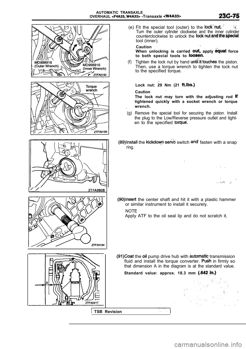
(e) Fit the special tool (outer) to the
Turn the outer cylinder clockwise and the inner cyl inder
counterclockwise to unlock the
tool (inner).
Caution
When unlocking is carried
apply force
to both special tools to
(f)Tighten the lock nut by hand the piston.
Then, use a torque wrench to tighten the lock nut
to the specified torque.
Lock nut: 29 Nm (21
Caution
The lock nut may turn with the adjusting rod
tightened quickly with a socket wrench or torque
wrench.
(g) Remove the special tool for securing the piston. In stall
the plug to the Low/Reverse pressure outlet and tight-
en to the specified
the switch fasten with a snap
ring.
the center shaft and hit it with a plastic hammer
or similar instrument to install it securely.
NOTE
Apply ATF to the oil seal lip and do not scratch it .
the pump drive hub with transmission
fluid and install the torque converter.
in firmly so
that dimension A in the diagram is at the standard value.
Standard value: approx. 18.3 mm
TSB Revision
Page 1386 of 2103
AUTOMATIC TRANSAXLE
Valve Body
solenoid
(3) Secure the lower valve body with mounting bolts and
then remove the special tool.
SOLENOID VALVE
(1) Install the solenoid valves as shown.
Solenoid valve
Shift control solenoid valve A (SCSV-A) Wire color
Orange
Shift control solenoid valve Yellow,
Torque converter clutch solenoid
solenoid)Red/Black
Pressure control solenoid valve (PCSV)
TSB Revision