Page 1562 of 2103
REAR AXLE Drive __
B O O T BA N D
( L A R G E )
INSTALLATION
Set the T.J. boot bands at the specified distance i n order
to adjust the amount of air inside the T.J.
and then
tighten the, T.J. boot bands securely.
Standard value (A): 79
3
84 3 mm in.)
Caution
Always check the identification numbers on the
band levers. Never confuse the bands.
Items Identification numberI
T.J. boot band (large)I
T.J. boot band (small)
INSPECTION
lCheck the drive Shaft for corrosion.
l drive shaft part for wear or damage.
lCheck for entry of water and/or foreign
l Check the spider assembly
corrosion.
lCheck the groove inside T.J. case for
lCheck the boots for deterioration, or
TSB Revision
Page 1615 of 2103
FRONT SUSPENSION , ,
Al
Clip ring ends onopposite side also possible)
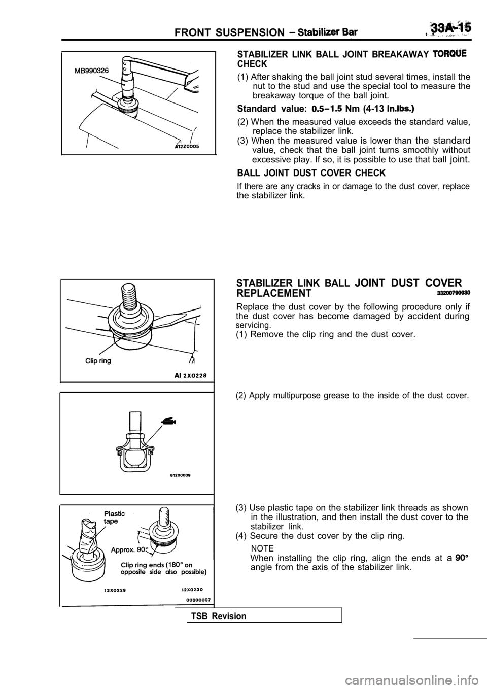
STABILIZER LINK BALL JOINT BREAKAWAY
CHECK
(1) After shaking the ball joint stud several times, install the
nut to the stud and use the special tool to measure the
breakaway torque of the ball joint.
Standard value: Nm (4-13
(2) When the measured value exceeds the standard va lue,
replace the stabilizer link.
(3) When the measured value is lower than the standard
value, check that the ball joint turns smoothly wit hout
excessive play. If so, it is possible to use that b all joint.
BALL JOINT DUST COVER CHECK
If there are any cracks in or damage to the dust co ver, replace
the stabilizer link.
STABILIZER LINK BALL JOINT DUST COVER
REPLACEMENT
Replace the dust cover by the following procedure o nly if
the dust cover has become damaged by accident durin g
servicing.
(1) Remove the clip ring and the dust cover.
(2) Apply multipurpose grease to the inside of the dust cover.
(3) Use plastic tape on the stabilizer link threads as shown
in the illustration, and then install the dust cove r to the
stabilizer link.
(4) Secure the dust cover by the clip ring.
NOTE
When installing the clip ring, align the ends at a
angle from the axis of the stabilizer link.
TSB Revision
Page 1635 of 2103
REAR SUSPENSION Stabilizer Bar
STABILIZER LINK BALL JOINT DUST
REPLACEMENT
Replace the dust cover by the following procedure only if
the dust cover has become damaged by accident durin g
servicing.
(1) Remove the clip ring and the dust cover.
Clip ring
Al
Clip ring ends on
opposite side also possible)
(2)Apply multi-purpose grease to the inside of the dus t cover.
(3) Use plastic tape on the stabilizer link threads as shown
in the illustration, and then install the dust cove r to the
stabilizer link.
(4) Secure the dust cover with the clip ring.
NOTE
When installing the clip ring, align the ends at a
angle from the axis of the stabilizer link.
TSB Revision
Page 1646 of 2103
BASIC BRAKE SYSTEM .,
d o w n ,
Lock nut
TSB Revision
O N - V E H I C L E
BRAKE PEDAL
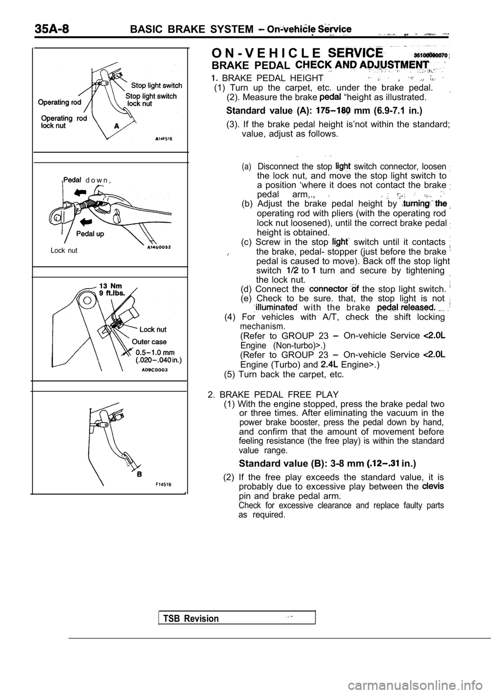
BRAKE PEDAL HEIGHT ,
(1) Turn up the carpet, etc. under the brake pedal.(2). Measure the brake
“height as illustrated.
Standard value (A): mm (6.9-7.1 in.)
(3). If the brake pedal height is’not within the st andard;
value, adjust as follows.
(a)Disconnect the stop switch connector, loosen
the lock nut, and move the stop light switch to
a position ‘where it does not contact the brake
pedal arm,.,
(b) Adjust the brake pedal height by
operating rod with pliers (with the operating rod
lock nut loosened), until the correct brake pedal
height is obtained.
(c) Screw in the stop
switch until it contacts
the brake, pedal- stopper (just before the brake
pedal is caused to move). Back off the stop light
switch
to turn and secure by tightening
the lock nut.
(d) Connect the
the stop light switch.
(e) Check to be sure. that, the stop light is not
with the brake
(4) For vehicles with A/T, check the shift locking
mechanism.
(Refer to GROUP 23 On-vehicle Service
Engine (Non-turbo)>.)
(Refer to GROUP 23 On-vehicle Service
Engine (Turbo) and Engine>.)
(5) Turn back the carpet, etc.
2. BRAKE PEDAL FREE PLAY (1) With the engine stopped, press the brake pedal two
or three times. After eliminating the vacuum in the
power brake booster, press the pedal down by hand,
and confirm that the amount of movement before
feeling resistance (the free play) is within the st andard
value range.
Standard value (B): 3-8 mm in.)
(2) If the free play exceeds the standard value, it is
probably due to excessive play between the
pin and brake pedal arm.
Check for excessive clearance and replace faulty pa rts
as required.
Page 1653 of 2103
BASIC BRAKE SYSTEM
Front hub assembly
196-255 Nm
145-188
3.
4.
5.
6.
8.
Remove the following parts from caliper support. 1. Pad and wear indicator assembly
2. Pad assembly
3. Clip
4 . O u t e r s h i m ( s t a i n l e s s )
5. Outer shim (coated with rubber)
6. Inner shim (stainless)
7. Inner shim (coated with rubber)
Take out the drive shaft. (Refer to GROUP 26
Drive
Shaft
to GROUP 26 Drive Shaft
Set the special tool to the front hub assembly as s hown
in the illustration.’
Measure hub torque (A) with pads removed to measure
brake drag torque. Torque value will be used later to
calculate brake drag force with the pads installed.
NOTE
Tighten the nuts in order to secure the disc to the hub.
Securely attach the pad clip to the caliper support .
Clean piston and insert into cylinder (caliper) with special
Page 1656 of 2103
BASIC BRAKE SYSTEM On-vehicle Service
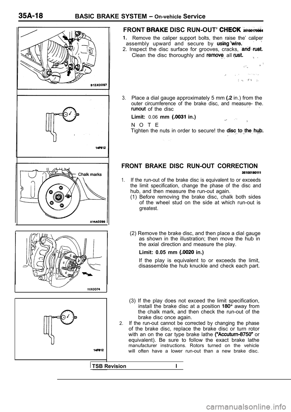
FRONT DISC RUN-OUT’
Remove the caliper support bolts, then raise the’ c aliper
assembly upward and secure by
2. Inspect the disc surface for grooves, cracks,
Clean the disc thoroughly and all
,
3.Place a dial gauge approximately 5 mm in.) from the
outer circumference of the brake disc, and measure- the.
of the disc
Limit:0.06mm in.)
N O T E
Tighten the nuts in order to secure! the
FRONT BRAKE DISC RUN-OUT CORRECTION
1.If the run-out of the brake disc is equivalent to o r exceeds
the limit specification, change the phase of the di sc and
hub, and then measure the run-out again.
(1) Before removing the brake disc, chalk both side s
of the wheel stud on the side at which run-out is
greatest.
(2) Remove the brake disc, and then place a dial ga uge
as shown in the illustration; then move the hub in
the axial direction and measure the play.
Limit: 0.05 mm
in.)
If the play is equivalent to or exceeds the limit,
disassemble the hub knuckle and check each part.
2.
(3) If the play does not exceed the limit specifica tion,
install the brake disc at a position
away from
the chalk mark, and then check the run-out of the
brake disc once again.
If the run-out cannot be corrected by changing the phase
of the brake disc, replace the brake disc or turn rotor
with an on the car type brake lathe
or
equivalent). Be sure to follow the exact brake lath e
manufacturer instructions. Rotors turned on the veh icle
will often have a lower run-out than a new brake di sc.
TSB RevisionI
Page 1660 of 2103
BASIC BRAKE SYSTEM On-vehicle Service
TSB Revision
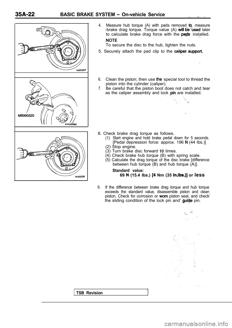
4.Measure hub torque (A) with pads removed measure
-brake drag torque. Torque value (A) later
to calculate brake drag force with the
installed.
To secure the disc to the hub, tighten the nuts.
5. Securely attach the pad clip to the
6.Clean the piston; then use special tool to thread the
piston into the cylinder (caliper).
7.Be careful that the piston boot does not catch and tear
as the caliper assembly and lock
are installed.
8. Check brake drag torque as follows.
(1) Start engine and hold brake pedal down for 5 second
s.
[Pedal depression force: approx. 196 (44 Ibs.)]
(2) Stop engine.
(3) Turn brake disc forward
times.
(4) Check brake hub torque (B) with spring scale.
(5) Calculate the drag torque of the disc brake [di fference
between hub torque (B) and hub torque (A)].
Standard value:
69 (15.4 Ibs.) Nm (35 or less
9.If the difference between brake drag torque and hub torque
exceeds the standard value, disassemble piston and clean
piston. Check for corrosion or piston seal, and check’
the sliding condition of the lock pin and’ pin.
Page 1661 of 2103
BASIC BRAKE SYSTEM On-vehicle Service
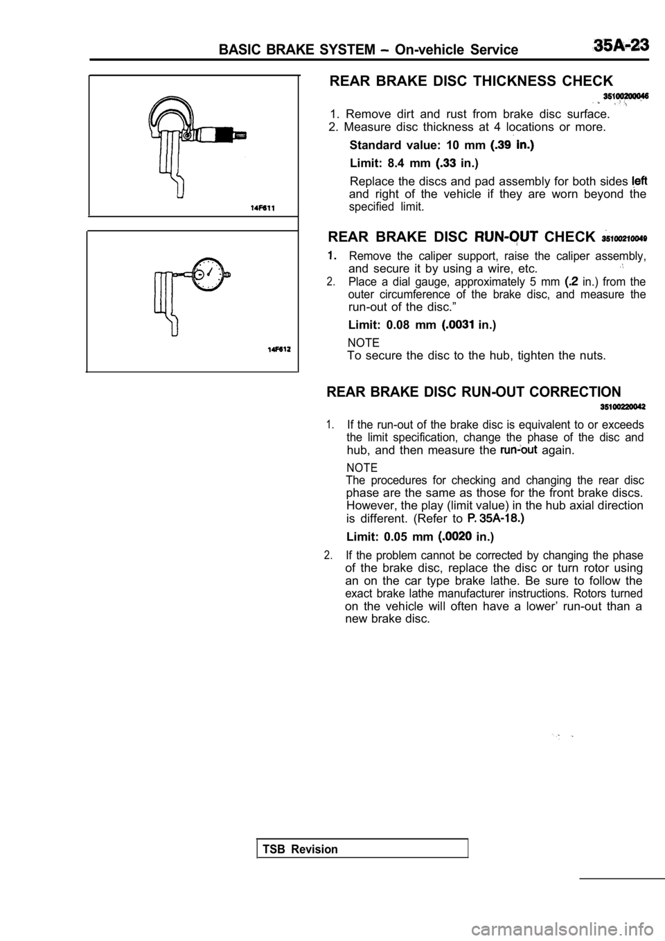
REAR BRAKE DISC THICKNESS CHECK
1. Remove dirt and rust from brake disc surface.
2. Measure disc thickness at 4 locations or more.
Standard value: 10 mm
Limit: 8.4 mm in.)
Replace the discs and pad assembly for both sides
and right of the vehicle if they are worn beyond th e
specified limit.
REAR BRAKE DISC CHECK
Remove the caliper support, raise the caliper assem bly,
and secure it by using a wire, etc.
2.Place a dial gauge, approximately 5 mm in.) from the
outer circumference of the brake disc, and measure the
run-out of the disc.”
Limit: 0.08 mm
in.)
NOTE
To secure the disc to the hub, tighten the nuts.
REAR BRAKE DISC RUN-OUT CORRECTION
1.If the run-out of the brake disc is equivalent to o r exceeds
the limit specification, change the phase of the di sc and
hub, and then measure the again.
NOTE
The procedures for checking and changing the rear d isc
phase are the same as those for the front brake discs.
However, the play (limit value) in the hub axial di rection
is different. (Refer to
Limit: 0.05 mm in.)
2.If the problem cannot be corrected by changing the phase
of the brake disc, replace the disc or turn rotor using
an on the car type brake lathe. Be sure to follow t he
exact brake lathe manufacturer instructions. Rotors turned
on the vehicle will often have a lower’ run-out tha n a
new brake disc.
TSB Revision