1990 MITSUBISHI SPYDER ECU
[x] Cancel search: ECUPage 355 of 2103
ENGINE OVERHAUL Shaft and Can
Case,
62
Crank pulley side
0
mm bolts
0
Oil pan viewed from lower side
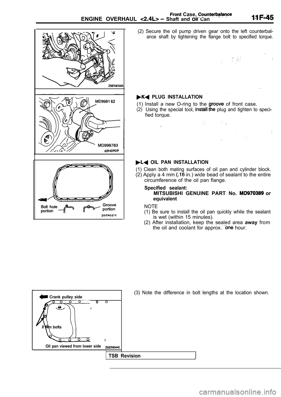
(2) Secure the oil pump driven gear onto the left counterbal-
ance shaft by tightening the flange bolt to specified torque.
PLUG INSTALLATION
(1) Install a new O-ring to the of front case.
(2)Using the special tool, plug and tighten to speci-
fied torque.
OIL PAN INSTALLATION
(1) Clean both mating surfaces of oil pan and cylin der block.
(2) Apply a 4 mm in.) wide bead of sealant to the entire
circumference of the oil pan flange.
Specified sealant:
MITSUBISHI GENUINE PART No. or
equivalent
NOTE
(1) Be sure to install the oil pan quickly while th e sealant
is wet (within 15 minutes).
(2) After installation, keep the sealed area awayfrom
the oil and coolant for approx.
hour.
(3) Note the difference in bolt lengths at the loca tion shown.
TSB Revision
Page 420 of 2103
![MITSUBISHI SPYDER 1990 Service Repair Manual ENGINE
I Scan tool 35
Code General scan tool
No.No Vehicle Speed Sensor Signal
15
[Comment]
Background
lThe speed sensor serves as a PCM input switching voltage between 0 an MITSUBISHI SPYDER 1990 Service Repair Manual ENGINE
I Scan tool 35
Code General scan tool
No.No Vehicle Speed Sensor Signal
15
[Comment]
Background
lThe speed sensor serves as a PCM input switching voltage between 0 an](/manual-img/19/57345/w960_57345-419.png)
ENGINE
I Scan tool 35
Code General scan tool
No.No Vehicle Speed Sensor Signal
15
[Comment]
Background
lThe speed sensor serves as a PCM input switching voltage between 0 and 5volts.lOnce the vehicle is in motion and the throttle is open, information from the sensor is
sampled every 11 milliseconds and compared to a min imum threshold equal to 1 mph.
lIf the sensors output voltage indicates a speed higher than this threshold, the sensor
is considered to be operating normally.
lFailure of the sensor would be quite noticeable bec ause the speedometer would fail tooperate.Diagnostic features that depend on the speed sensor may never execute if this component
fails.
of Check Engine coolant temperature: or more Transaxle: Other than or range only). 31 seconds after starting engine Brakes not applied Throffle valve: Open Engine: 1600 or more Difference between the atmospheric pressure and in take manifold pressure:
34 (10 or more Condition Vehicle speed: Less than lmph for 11 seconds
Measure at the speed sensor connector
l Disconnect the connector, and measure at the harnes s side.
l Voltage between 1 and ground
(Ignition switch: ON)
O K :
l Continuity between 2 and ground
OK: Continuity
OK
OK
Check trouble
Open or shorted. circuitS p e e d o m e t e r d a m a g e d Open supply circuit
Open sensor ground circuit
Vehicle speed sensor failed PCM failed
Repair
Check the harness wire between the PCM and the spee d sensor
connector. Repair, if necessary.
N G Check the following connectors: I Repair
SCAN TOOL SENSOR READ TESTS (Data list)
Replace the vehicle speed sensor.
connector.
N G NG
Repair
TSB Revision
Page 508 of 2103
28 of
( N O N - T U R B O ) >
Bottom view
of relay
I
Intake air temperature
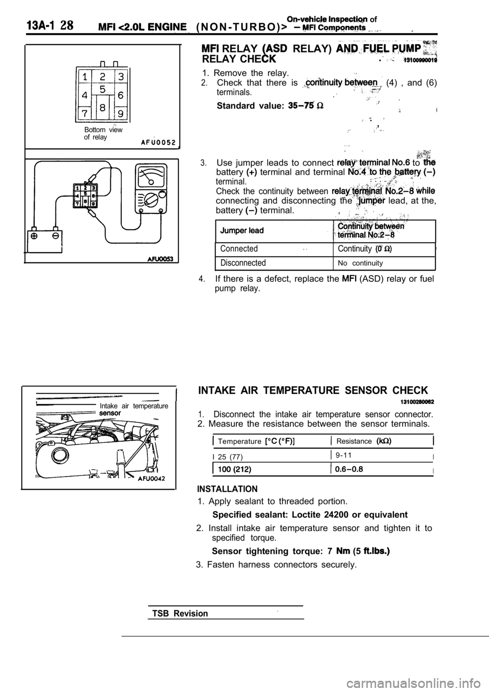
RELAY RELAY)
RELAY CHE.
1. Remove the relay.
2.Check that there is (4) , and (6)
terminals..
Standard value:
.,
3.Use jumper leads to connect to
battery terminal and terminal
terminal.. . .
Check the continuity between
connecting and disconnecting the lead, at the,
battery
terminal. ,
Connected
DisconnectedContinuity
No continuity
4.If there is a defect, replace the (ASD) relay or fuel
pump relay.
INTAKE AIR TEMPERATURE SENSOR CHECK
1.Disconnect the intake air temperature sensor connec tor.
2. Measure the resistance between the sensor terminals.
Temperature Resistance
I 25 (77) 9 - 1 1I
I
INSTALLATION
1. Apply sealant to threaded portion.
Specified sealant: Loctite 24200 or equivalent
2. Install intake air temperature sensor and tighte n it to
specified torque.
Sensor tightening torque: 7 (5
3. Fasten harness connectors securely.
TSB Revision
Page 509 of 2103
On-vehicle Inspection of
ENGINE
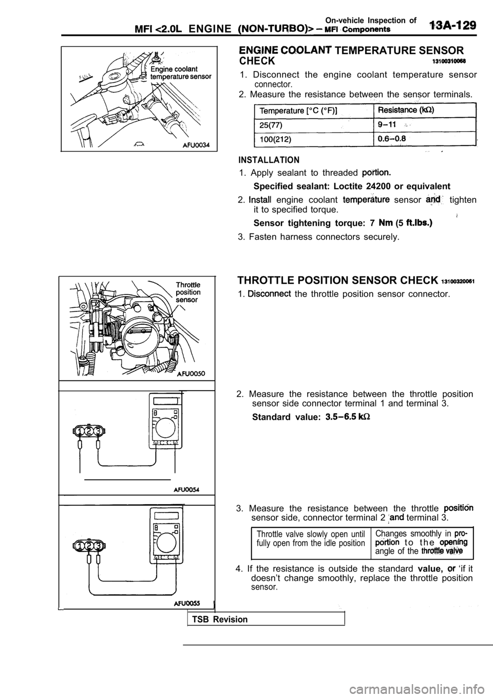
TEMPERATURE SENSOR
CHECK
1. Disconnect the engine coolant temperature sensor
connector.
2. Measure the resistance between the sensor terminals.
INSTALLATION
1. Apply sealant to threaded
Specified sealant: Loctite 24200 or equivalent
2.
engine coolant sensor tighten
it to specified torque.
Sensor tightening torque: 7 (5
3. Fasten harness connectors securely.
THROTTLE POSITION SENSOR CHECK
1. the throttle position sensor connector.
2. Measure the resistance between the throttle posi tion
sensor side connector terminal 1 and terminal 3.
Standard value:
3. Measure the resistance between the throttle
sensor side, connector terminal 2 terminal 3.
Throttle valve slowly open until
fully open from the idle positionChanges smoothly in
t o t h e
angle of the
4. If the resistance is outside the standard value, ‘if it
doesn’t change smoothly, replace the throttle posit ion
sensor.
TSB Revision
Page 555 of 2103
![MITSUBISHI SPYDER 1990 Service Repair Manual ENGINE (TURBO)
ENGINE>
Code No. Misfire Detected (Cylin-
der-l,
[Comment]Background
lif a misfiring occurs while the engine is running, the engine speed suddenly changes.
l Th MITSUBISHI SPYDER 1990 Service Repair Manual ENGINE (TURBO)
ENGINE>
Code No. Misfire Detected (Cylin-
der-l,
[Comment]Background
lif a misfiring occurs while the engine is running, the engine speed suddenly changes.
l Th](/manual-img/19/57345/w960_57345-554.png)
ENGINE (TURBO)
ENGINE>
Code No. Misfire Detected (Cylin-
der-l,
[Comment]Background
lif a misfiring occurs while the engine is running, the engine speed suddenly changes.
l The engine control module checks for changes in the engine speed.
Check Areal 5 or more have passed after the engine was started.l Engine speed is at between 500 and 6000 l Engine coolant temperature is or higher.
l Intake air temperature is or higher
l Barometric pressure is 76 (11 psi.) or higher.
l Running free from sudden accelerations/deceleration s such as shift change.
Judgement Criteria(change in the angular acceleration of the crankshaft is used for misfire detection.)lMisfire has occurred more frequently than allowed during the last 200 revolutions [when
the catalyst temperature is higher than
or l Misfire has occurred in 20 or more of the last 1000 revolutions (corresponding to 1.5
times the limit of emission standard.)
l l Low compression l Injector failed
l Engine
Check the injector (Refer
OK
Replace
Check the following connectors: __ Repair,OK
[Check the harness wire between the ECM and the inj ectorNG ,
connector
Check the following items.
l Check the spark plugs, spark plug cables.
l Check the compression pressure
Code No. Knock Sensor 1 Circuit Malfunction
Engine (Turbo)>
l sensor failed BackgroundlThe knock sensor converts the vibration of the cyli nder block into a voltage and outputs
it. If there is a malfunction of the knock sensor, the voltage output will not change.
l The engine control module checks whether the voltag e output changes.
Check Areal Ignition switch: ONl60 or more have passed after the ignition switch was turned on or the starting sequencewasl Engine speed is higher than 2000
Judgement CriterialKnock sensor output voltage (knock sensor peak volt age in each deg period of the
crankshaft) has not changed more than 0.06 in the last consecutive 200 periods.
lOpen or shorted knock sensor circuit, or connector
l Engine control module failed
Revision
Page 566 of 2103
![MITSUBISHI SPYDER 1990 Service Repair Manual ENGINE (TURBO)
AND ENGINE> Troubleshooting
Code No. Evaporative Emission
Pressure Sensor Malfunction Engine>
[Comment]Background
lThe fuel tank differential pressure sensor outputs MITSUBISHI SPYDER 1990 Service Repair Manual ENGINE (TURBO)
AND ENGINE> Troubleshooting
Code No. Evaporative Emission
Pressure Sensor Malfunction Engine>
[Comment]Background
lThe fuel tank differential pressure sensor outputs](/manual-img/19/57345/w960_57345-565.png)
ENGINE (TURBO)
AND ENGINE> Troubleshooting
Code No. Evaporative Emission
Pressure Sensor Malfunction Engine>
[Comment]Background
lThe fuel tank differential pressure sensor outputs the voltage in proportion to the pressurein the fuel tank. (differential pressure against the barometric pressure)
l The engine control module checks whether the output voltage of the fuel tank differential
pressure sensor is within the specified range
Check Area, Judgement Criteria 1. Check Area
l Engine speed is not lower than 1500
l Volumetric efficiency is between 25
Judgement Criterial
The sensor output voltage is 4.5 or higher for 10 seconds even though the intake
air temperature is between 5” and the evaporative emission
purge solenoid is being driven at 100% duty.
or
l The sensor output voltage is 0.5
or lower for 10 seconds even though the intake
air temperature is (41 or higher and the evaporative emission purge solen oid
is not being driven.
2. Check Area l The pressure fluctuates 20 times or more at 0.2
or higher.
l Closed position switch: ON
Judgement Criterial
The pressure fluctuates 20 times or more (0.2 or higher) for 15 consecutive idleoperations.
Fuel tank differential pressure Openor shorted fuel o r Engine control module ,
.
Disconnect the connector and measure at the harness side.
2. Continuity between 2 and ground OK: Continuity
OK
NGCheck the following Repair
NGNGCheck the harness Repair
between fuel tank differ-
ential
sensor and
Replace the fuel tank differential pressure sensor.
NGNGCheck the harness wire
between fuel tank differ-
/ Check
Check the harness wire between fuel tank differenti al pressure
sensor and ground. Repair, if necessary.
T S B R e v i s i o n
Page 628 of 2103
ENGINE (TURBO)
AND ENGINE> Troubleshooting
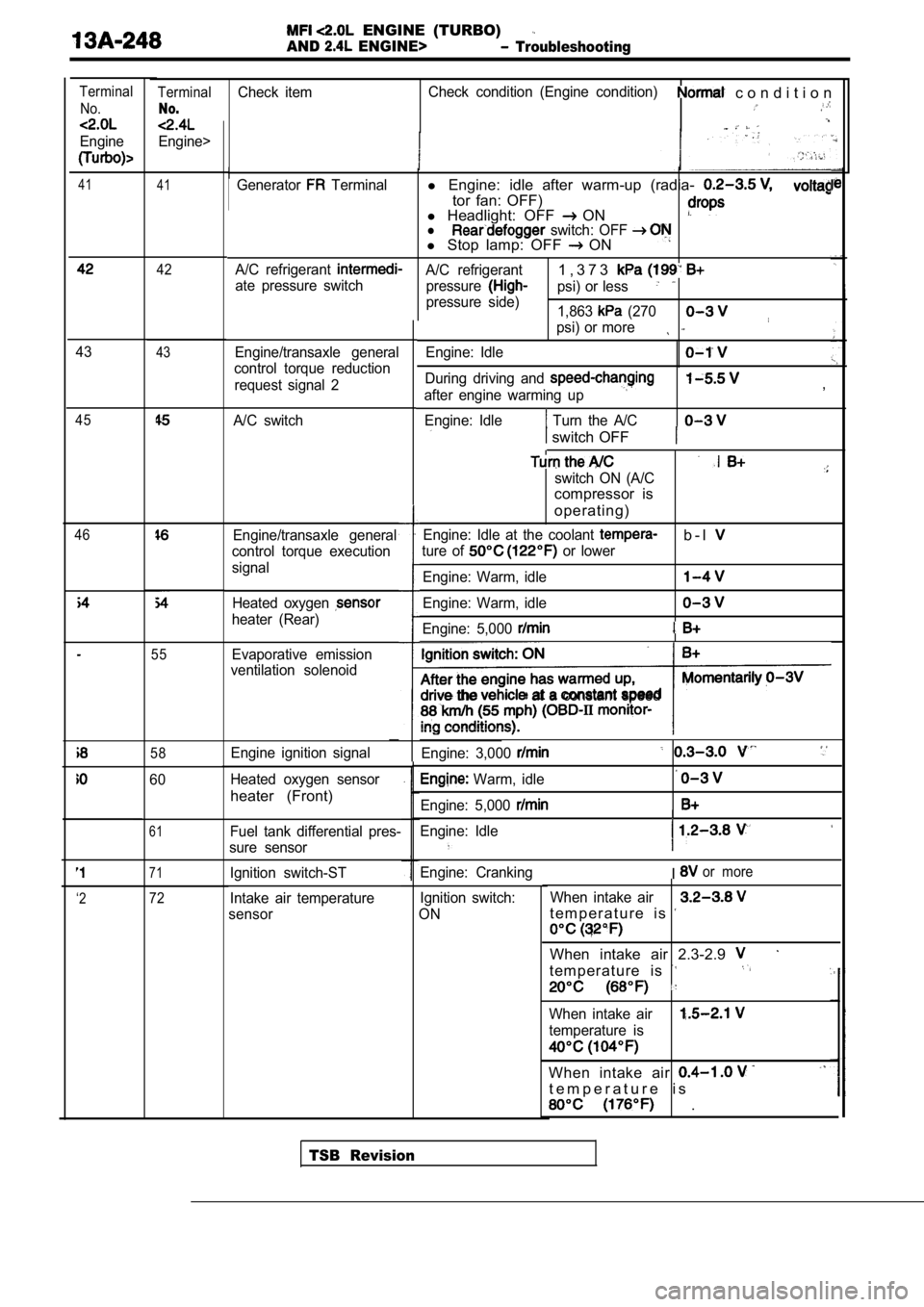
TerminalCheck itemCheck condition (Engine condition) c o n d i t i o n
No.
Engine>
Terminal
No.
Engine
41 41Generator Terminall Engine: idle after warm-up (radia-
tor fan: OFF)
l Headlight: OFF ONl switch: OFF l Stop lamp: OFF ON
A/C refrigerant A/C refrigerant1 , 3 7 3
ate pressure switch
pressurepsi) or less
pressure side)
1,863 (270
psi) or more
Engine/transaxle general
control torque reduction
request signal 2 Engine: Idle
During driving and
after engine warming up
Engine: Idle
Turn the A/C
,
switch OFF
switch ON (A/C
compressor is
operating)
Engine: Idle at the coolant b - l
ture of or lower
Engine: Warm, idle
Engine: Warm, idle
Engine: 5,000
the at a constant speed
Engine: 3,000
Warm, idle
Engine: 5,000
Engine: Idle
I
Engine: CrankingIor more
Ignition switch:
ON When intake air
t e m p e r a t u r e i s
When intake air 2.3-2.9
t e m p e r a t u r e i s
When intake air
temperature is
When intake air
t e m p e r a t u r e i s
.
42
4343
A/C switch45
46Engine/transaxle general
control torque execution
signal
Heated oxygen
heater (Rear)
55Evaporative emission
ventilation solenoid
58Engine ignition signal
Heated oxygen sensor
heater (Front)
60
61Fuel tank differential pres-
sure sensor
71Ignition switch-ST
Intake air temperature
sensor
‘272
TSB Revision
Page 645 of 2103
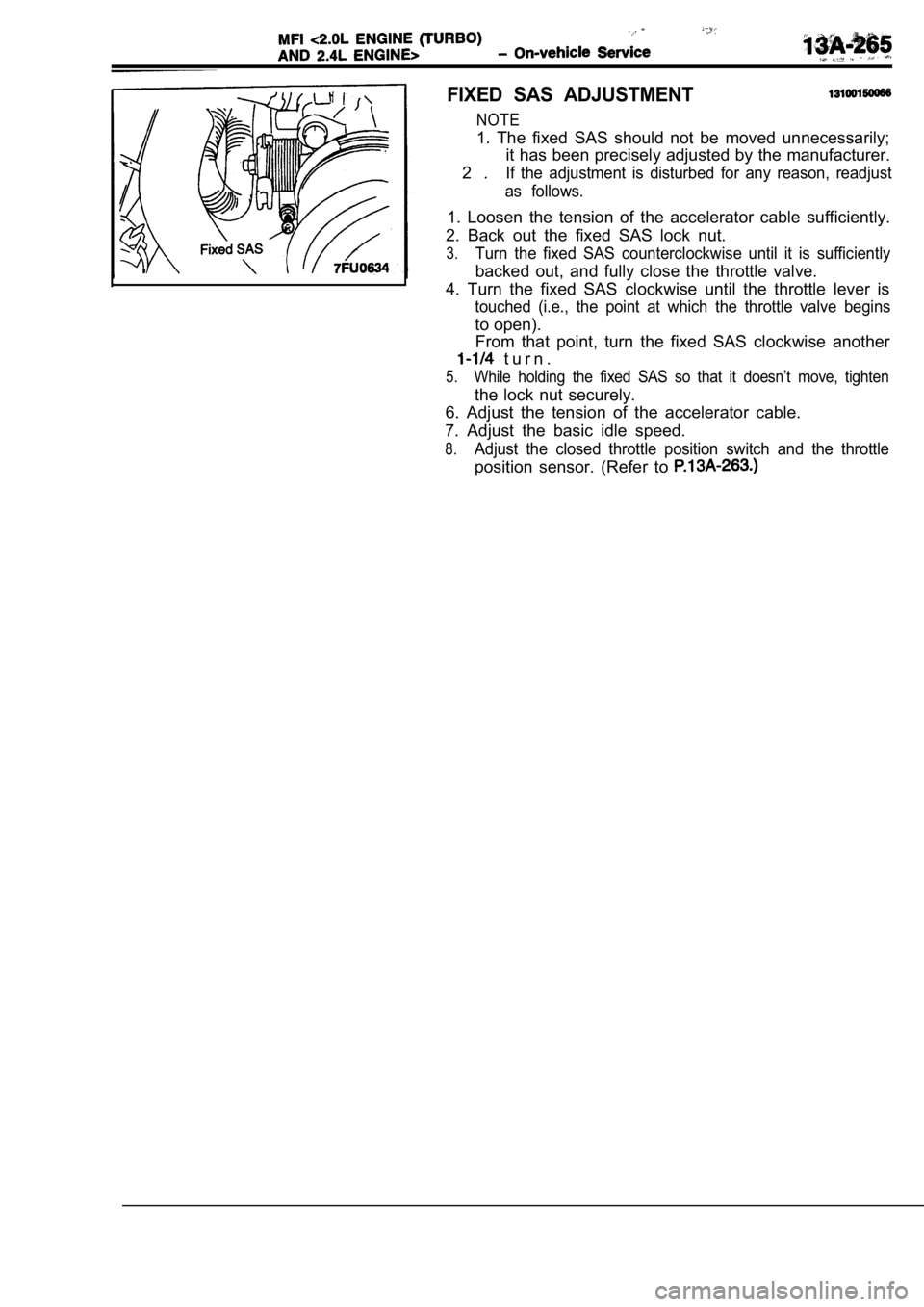
FIXED SAS ADJUSTMENT
NOTE
1. The fixed SAS should not be moved unnecessarily;it has been precisely adjusted by the manufacturer.
2 .
If the adjustment is disturbed for any reason, read just
as follows.
1. Loosen the tension of the accelerator cable suff iciently.
2. Back out the fixed SAS lock nut.
3.Turn the fixed SAS counterclockwise until it is suf ficiently
backed out, and fully close the throttle valve.
4. Turn the fixed SAS clockwise until the throttle lever is
touched (i.e., the point at which the throttle valve begins
to open).
From that point, turn the fixed SAS clockwise anoth er
t u r n .
5.While holding the fixed SAS so that it doesn’t move , tighten
the lock nut securely.
6. Adjust the tension of the accelerator cable.
7. Adjust the basic idle speed.
8.Adjust the closed throttle position switch and the throttle
position sensor. (Refer to