Page 1915 of 2103

BODY Convertible Top
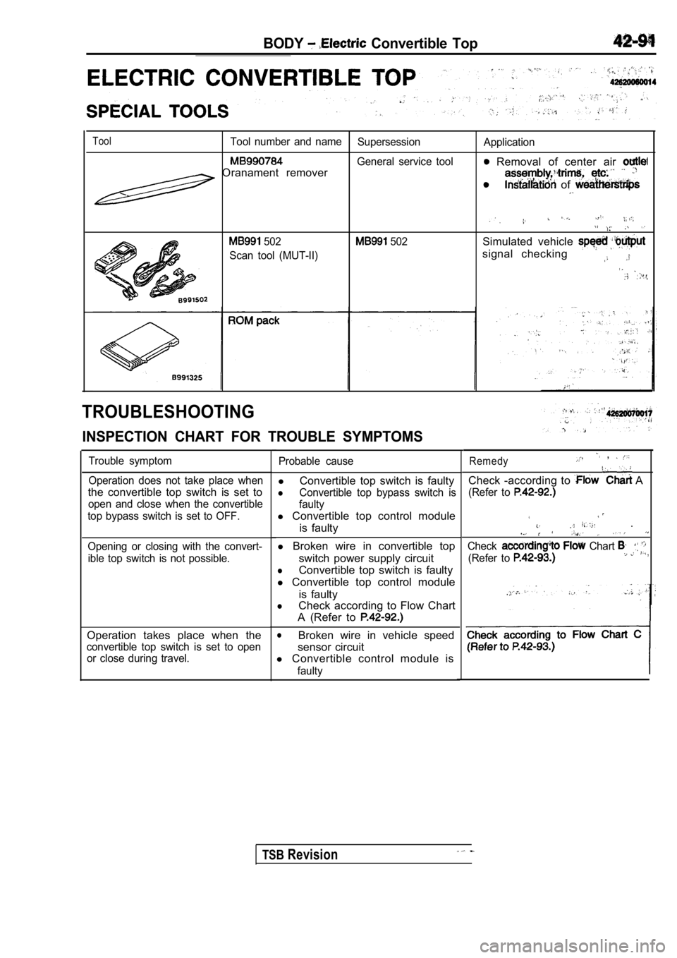
ToolTool number and nameSupersessionApplication
General service tool Removal of center air Oranament remover
of
502
Scan tool (MUT-II) 502Simulated vehicle
signal checking
TROUBLESHOOTING
INSPECTION CHART FOR TROUBLE SYMPTOMS
Trouble symptom
Operation does not take place when
the convertible top switch is set to
open and close when the convertible
top bypass switch is set to OFF.
Opening or closing with the convert- ible top switch is not possible.
Operation takes place when the
convertible top switch is set to openor close during travel. Probable cause
l
Convertible top switch is faulty
lConvertible top bypass switch is
faulty
l Convertible top control module
is faulty
l Broken wire in convertible top
switch power supply circuit
lConvertible top switch is faulty
l Convertible top control module
is faulty
lCheck according to Flow Chart
A (Refer to
lBroken wire in vehicle speed
sensor circuit
l Convertible control module is
faulty
Remedy ,
Check -according to A
(Refer to
.
Check Chart
(Refer to ,
TSBRevision
Page 1919 of 2103
BODY Electric Convertible
REMOVAL SERVICE POINTS .
CLIP REMOVAL
out 2 clips at each using the prying tool.
TROUGH REAR CLIP
REMOVAL
Using the clip tool, 10 attaching clips.
Caution
Use care not to rip the drain trough during
top removal.
CONVERTIBLE TOP ASSEMBLY REMOVAL
Pty one side back at a time.
Caution
Use care not to rip the drain trough durlng convertible
top removal.
TSB Revision
SERVICE POINT
CONVERTIBLE TOP ASSEMBLY INSTALLATION
(1) Insert rear bow into back of top area first.
Caution
Use care not to rip the drain trough during convert ible
top removal.
(2) Snug frorit bolts first, then insert rear bolts .
Page 1920 of 2103
42-96BODY Electric Convertible
DRIVEN GEAR
REMOVAL AND INSTALLATION
Removal steps
l Quarter trim, lower (Refer to GROUP Trims.)
1. Balance link installation screw
2. Bushing
3. Main pivot bolt
4. Bushing 5. driven gear
B u s h i n g
REMOVAL SERVICE POINT
DRIVEN GEAR REMOVAL
Lift pivot and support with 102 mm
366 mm 279 mm
(4 in.
14 in. 11 in.) block of wood or equivalent.
INSTALLATION SERVICE POINTS
DRIVEN GEAR/BUSHING
INSTALLATION
(1) Position the driven gear and insert the main
pivot bolt, then tighten two driven gear installation
bolts.
(2) Remove the main pivot bolt.
(3) Install the driven gear to the main pivot complete
bracket.
NOTE
To align motor drive gear and driven gear, change
Bypass switch in left rear of trunk to manual posit ion.
Revision
Page 1922 of 2103
42-98BODY Electric Convertible Top
HEADLINER
REMOVAL AND INSTALLATION
‘3
Removal steps
1. Snaps2. Front headliner attaching strap
3. Center headliner attaching strap
4. Headliner
REMOVAL SERVICE POINTS
FRONT HEADLINER ATTACHING STRAPREMOVAL
From a completely closed position, open the convert ible top
half-way.
HEADLINER REMOVAL
Mark the bows lightly at the end of each retainer, then pry
the retainer from the bow. Remove the headliner.
INSTALLATION SERVICE POINT
HEADLINER INSTALLATION
Hook headliner retainer to back side of bow, then a lign the
end of the retainer with the mark and snap front of retainer
onto bow completely.
Page 1923 of 2103
BODY Convertible’
DRIVE MOTOR
REMOVAL AND INSTALLATION
Post-installation OperationConvertibletop fit adjustment (Refer to 1
20 25
1 4 - 1 8
2
Removal steps
l Quarter trim, lower (Refer to GROUP
Trims.)
l Rear speaker bracket A (Refer to
GROUP 54
Speaker.)
1. Rear speaker bracket
2. Spacer
3. drive motor
NOTE
This illustration shows the right side.
The left side is symmetrical to the right side.
REMOVAL SERVICE
MOTOR
Remove lower bolts with spacers first, then upper b olts.
INSPECTION
(1) Check that the motor runs smoothly when the bat tery
is connected directly to the motor terminals.
(2) Furthermore, check that the motor operates in r everse
when the terminal connections are switched.
Page 1926 of 2103
BODY Electric Convertible Top
BALANCE LINK
REMOVAL AND INSTALLATION
I
Removal steps
Quarter trim, lower(Refer to GROUP Trims.)
1. Front healiner attaching strap
2. Center headliner attaching strap
3. Bushing4. Balance link
NOTE
This illustration shows the left side.
The right side is symmetrical to the
side.
REMOVAL SERVICE POINT
FRONT HEADLINER ATTACHING STRAP
REMOVAL
From a fully closed position, raise the convertible top 102
mm to 153 mm (4 in.
6 in.)
TSB Revision
Page 1927 of 2103
BODY Electric Convertible Top
CONVERTIBLE TOP SWITCH
REMOVAL
42620240012
A N D I N S T A L L A T I O N
NOTE indicates the metal clip position.
Removal steps
1. Stopper 2. Center air outlet assembly3. Convertible top switch
REMOVAL SERVICE POINT
AIR OUTLET ASSEMBLY REMOVAL
Using the pry tool, carefully pry the assembly out of the
INSTALLATION SERVICE POINT
CENTER AIR OUTLET ASSEMBLY
INSTALLATION
(1) Turn the cool air bypass lever of the center ai r outlet
fully downward.
(2) Pull the cool air bypass damper lever on the heater unit
side fully toward you, then attach the cable to the pin
of the
(3) Push the outer cable in the direction of the ar row so
there is no looseness, then secure it with the clip.
TSB Revision
Page 1928 of 2103
BODY Electric Convertible
. .INSPECTION,
Switch position
45
OPEN0 0
CLOSE0 0
CONVERTIBLE TOP BYPASS SWITCH
REMOVAL AND INSTALLATION
Removal steps
1. Convertible top bypass switch
LidREMOVAL SERVICE POINT
TOP BYPASS REMOVAL
(1) Slide the lock knob of the lid in the of the arrow
in the illustration to remove lid.
TSB Revision