Page 1857 of 2103

BODY,
SERVICE SPECIFICATIONS
Items
Inside handle play mm (in.)Standard value .
6.2 or more
Outside handle play mm (in;)
Clearance of door window Adjustment of glass inclin ation
glass to weatherstripamount
holder mm (in.)
Adjustment of glass longitudinal
inclination
Clearance between door window glass and door window glass
catch mm (in.)
Overlap margin between door window glass and door w indow
glass catch mm (in.)
Distance between door window glass and weatherstrip step line
mm (in.)
4.4 more
Front pillar37.0
Roof or convertible3 1
Front pillar
1.6
Roof or convertible1
Quarter pillar
1 3 . 0 1.0
Front pillar
SEALANT
Roof or Convertible 6.3 1
Quarter pillar 13.0 1
Front pillar
R o o f o r C o n v e r t i b l e 1
Front pillar
1.6
Roof or Convertible 1 I
Items Specified sealantII
Waterproof film ATD Part No. 8625 or equivalent
SPECIAL TOOLS
ToolTool number and nameApplication
General service toolRemoval of switch, trim,. etc.
remover
Adjustment of door fit
Door adjusting wrench
TSB Revision
Page 1872 of 2103

42-48BODY Door
Delta sashInner stabilizer
track
ON-VEHICLE SERVICE
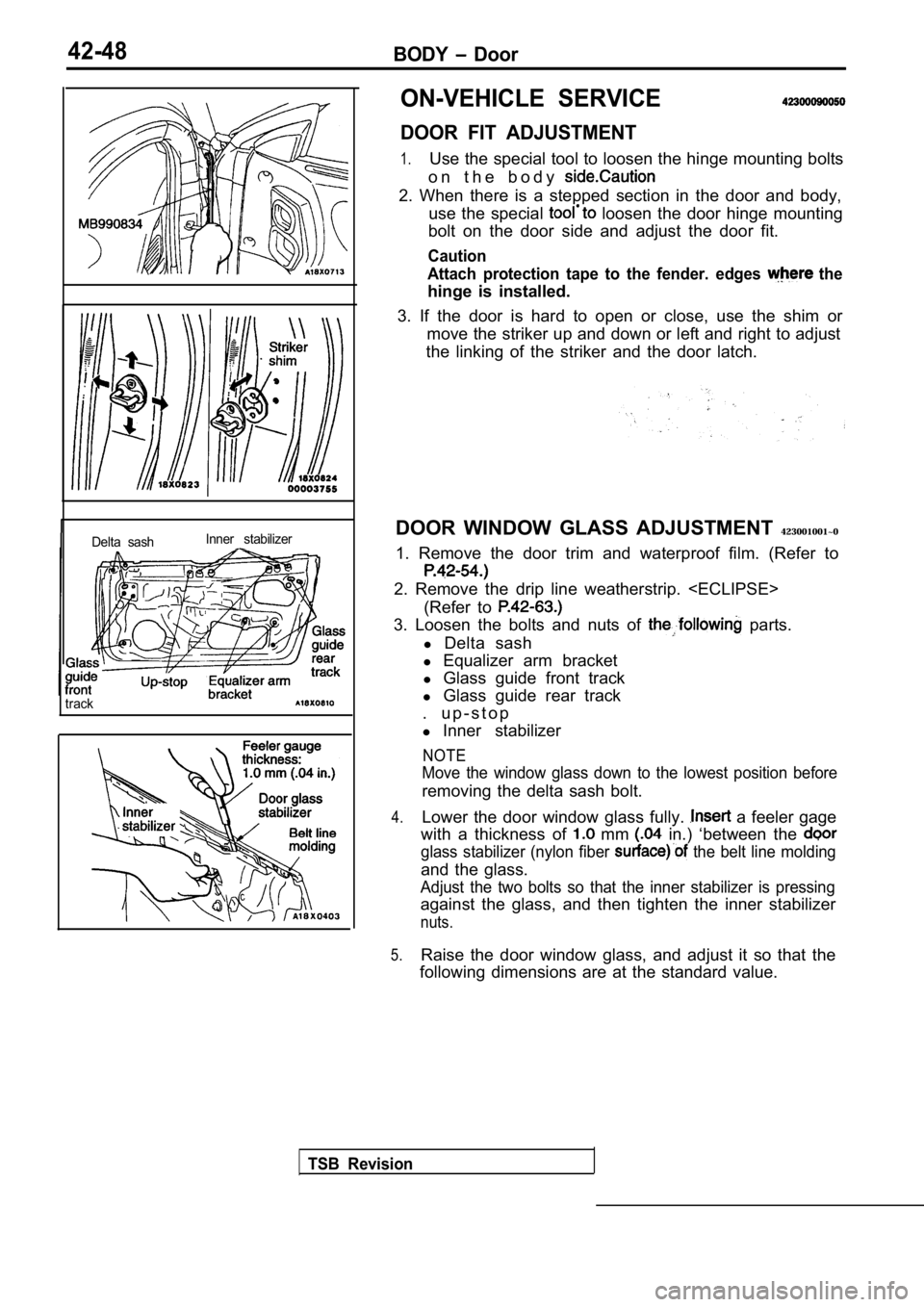
DOOR FIT ADJUSTMENT
1.Use the special tool to loosen the hinge mounting b
olts
o n t h e b o d y
2. When there is a stepped section in the door and body,
use the special
loosen the door hinge mounting
bolt on the door side and adjust the door fit.
Caution
Attach protection tape to the fender. edges
the
hinge is installed.
3. If the door is hard to open or close, use the sh im or
move the striker up and down or left and right to a djust
the linking of the striker and the door latch.
DOOR WINDOW GLASS ADJUSTMENT 423001001~0
1. Remove the door trim and waterproof film. (Refer to
2. Remove the drip line weatherstrip.
(Refer to
3. Loosen the bolts and nuts of parts.
l Delta sash
l Equalizer arm bracket
l Glass guide front track
l Glass guide rear track
. u p - s t o p
l Inner stabilizer
NOTE
Move the window glass down to the lowest position b efore
removing the delta sash bolt.
4.Lower the door window glass fully. a feeler gage
with a thickness of
mm in.) ‘between the
glass stabilizer (nylon fiber the belt line molding
and the glass.
Adjust the two bolts so that the inner stabilizer i s pressing
against the glass, and then tighten the inner stabi lizer
nuts.
5.Raise the door window glass, and adjust it so that the
following dimensions are at the standard value.
TSB Revision
Page 1879 of 2103
BODY Door
0 0 0 0 0 1 2 4
Front of vehicle
Cover
section
Door inside handle
l i n e
Front of vehicle
R E M O V A L
(A, CLIP REMOVAL
Remove the clip by using a shop and then
the regulator handle.
COVER REMOVAL
Remove the cover mounting screw and cover
by pushing it toward the front of the vehicle to ‘r emove the
clamp section from the door inside handle.
DOOR TRIM REMOVAL
After removing the trim mounting screws and clips, push
the trim to remove it from the door weatherstnp
clips.
INSTALLATION SERVICE
REGULATOR INSTALLATION
(1) Install the escutcheon and the clip to the regulator handle.
(2) Fully close the door glass, and install the reg ulator handle
so that itfaces as shown in the illustration.
,
TSB Revision
Page 1888 of 2103
BODY Door
REMOVAL AND INSTALLATION
1 ’
Door inner opening weatherstripremoval steps
l Scuff plate (Refer to GROUP Trims.)1. Door inner front openingweatherstrip2. Door inner rear openingweatherstrip
TSB Revision
REMOVAL SERVICE POINT
DOOR OUTER OPENING WEATHERSTRIP
REMOVAL
Make a tool as shown in the illustration to the door
opening weatherstrip.
Page 1894 of 2103
BODY Trunk Lid
Slit
I
I
Trunk lid opening weatherstrip
Trunk lid
in.)
Bumper
REMOVAL SERVICE POINT
LOCK COVER
a flat-tip screwdriver, etc., into the slit, and r emove
the lock cover.
INSTALLATION SERVICE POINTS
TRUNK LID OPENING WEATHERSTRIP
INSTALLATION
(1)Install the trunk lid opening weatherstrip so that the marked
part is at the position shown in the illustration.
(2) Install so that the notch on the trunk lid open ing
weatherstrip is approximately at the center of the panel
notch shown in the illustration.
BUMPER INSTALLATION
Install the bumper as shown in the figure.
TSB RevisionI
Page 1906 of 2103

42-82BODY Sunroof
SUNROOF
GENERAL
A motor-driven outer slide-type glass sunroof with
a tilt-up mechanism is provided as an option fora sufficient amount of lighting and a feeling of
all models. Even when the sunroof is fully closed,
openness can still be obtained by opening the
sunroof sunshade.
SEALANT AND ADHESIVE
Items
Sunroof glass attaching screws
Sunroof glass sealing Specified sealant and adhesive
Loctite Small Screw Threadlocker 222 or equivalent
410 Black Toughened Instant Adhesive or
equivalent
in.)
Hose
ON-VEHICLE SERVICE
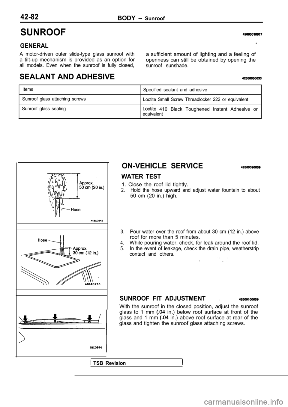
WATER TEST
1. Close the roof lid tightly.
2.Hold the hose upward and adjust water fountain to a bout
50 cm (20 in.) high.
3.Pour water over the roof from about 30 cm (12 in.) above
roof for more than 5 minutes.
4.While pouring water, check, for leak around the roof lid.
5.In the event of leakage, check the drain pipe, weatherstrip
contact and others.
SUNROOF FIT ADJUSTMENT.
With the sunroof in the closed position, adjust the sunroof
glass to 1 mm
in.) below roof surface at front of the
glass and 1 mm
in.) above roof surface at rear of the
glass and tighten the sunroof glass attaching screw s.
TSB Revision
Page 1910 of 2103
BODY Sunroof
ADHESION POINTS
glass seal
I -i
Sunroof glass attaching
screw
I
0 0 0 0 3 8 1 4
Sealant:
Loctite Small Screw Threadlocker 222orequivalent
REMOVAL SERVICE POINTS
SUNROOF GLASS REMOVAL
(1) Tilt the sunroof.
(2) Remove the screws attaching sunroof glass to th e guide
assemblies, and then lift the glass out of roof
SUNROOF GLASS SEAL REMOVAL
Remove the seal by pulling it off of glass staring at the splice
joint.
TSB Revision
Page 1912 of 2103

42-88BODY Sunroof
Front
Rear
Sunroof
cable end
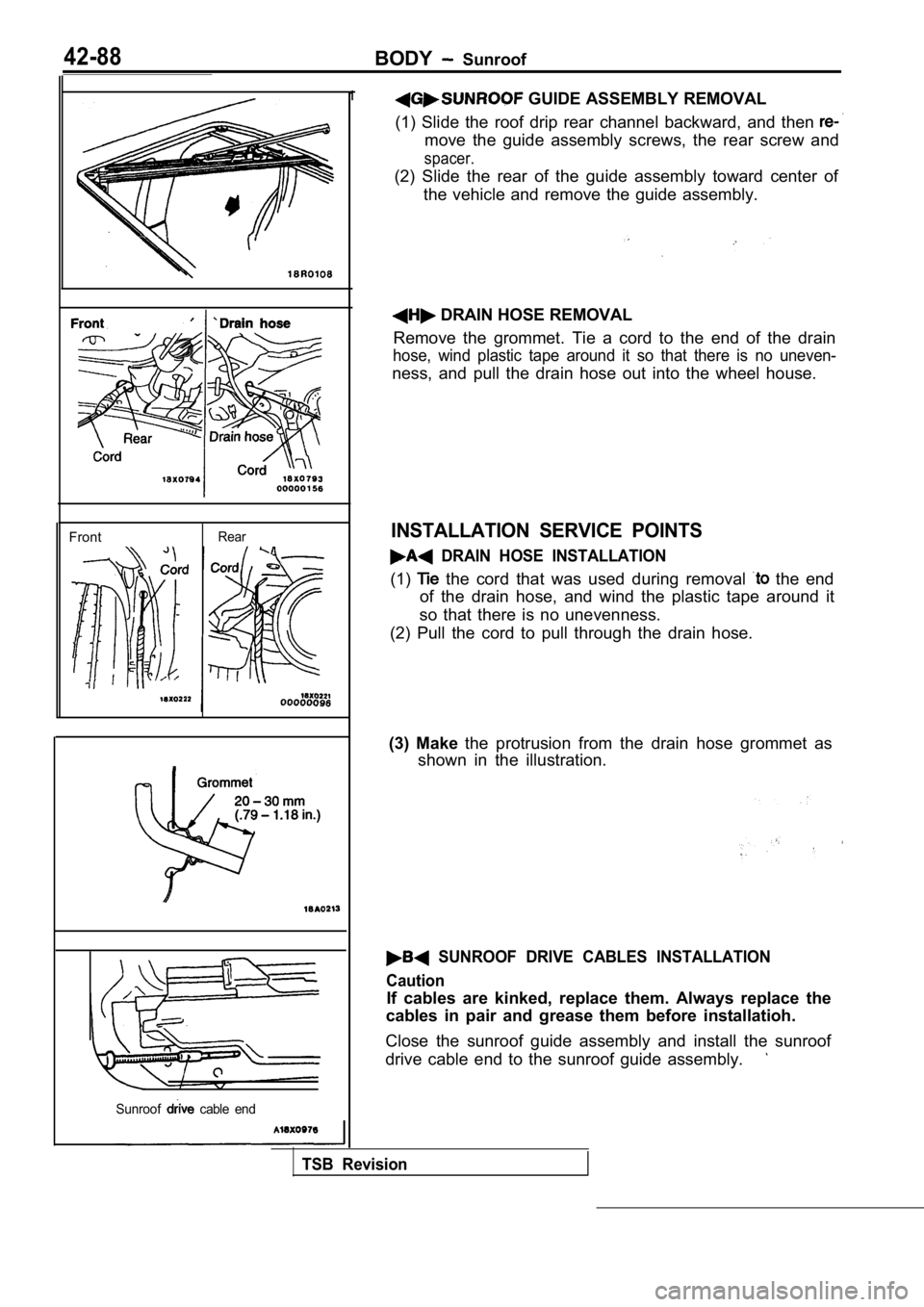
1 GUIDE ASSEMBLY REMOVAL
(1) Slide the roof drip rear channel backward, and then
move the guide assembly screws, the rear screw and
spacer.
(2) Slide the rear of the guide assembly toward cen ter of
the vehicle and remove the guide assembly.
DRAIN HOSE REMOVAL
Remove the grommet. Tie a cord to the end of the dr ain
hose, wind plastic tape around it so that there is no uneven-
ness, and pull the drain hose out into the wheel ho use.
INSTALLATION SERVICE POINTS
DRAIN HOSE INSTALLATION
(1) the cord that was used during removal the end
of the drain hose, and wind the plastic tape around it
so that there is no unevenness.
(2) Pull the cord to pull through the drain hose.
(3) Make the protrusion from the drain hose grommet as
shown in the illustration.
SUNROOF DRIVE CABLES INSTALLATION
Caution
If cables are kinked, replace them. Always replace the
cables in pair and grease them before installatioh.
Close the sunroof guide assembly and install the su nroof
drive cable end to the sunroof guide assembly.
TSB Revision