1990 MITSUBISHI SPYDER service
[x] Cancel search: servicePage 2074 of 2103
55-34HEATER, AIR
AND VENTILATION
Compressor and Tension Pulley
Engine (Turbo) and
DISASSEMBLY AND REASSEMBLY55200460070
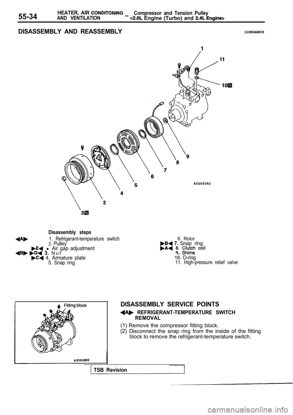
Disassembly steps
1. Refrigerant-temperature switch2.Pulley l Air gap adjustment 3. N u t 4. Armature plate5. Snap ring
6. Rotor 7. Snap ring.
O-ring11. High-pressure relief valve
DISASSEMBLY SERVICE POINTS
REFRIGERANT-TEMPERATURE SWITCH
REMOVAL
(1) Remove the compressor fitting block.
(2) Disconnect the snap ring from the inside of the fitting
block to remove the refrigerant-temperature switch.
TSB Revision
Page 2075 of 2103
HEATER, AIR Compressor and Tension Pulley
AND VENTILATION Engine (Turbo) and Engine>55-35
Clutch coil
Clutch coilSnap-ringI
Crankshaft
Serration notch
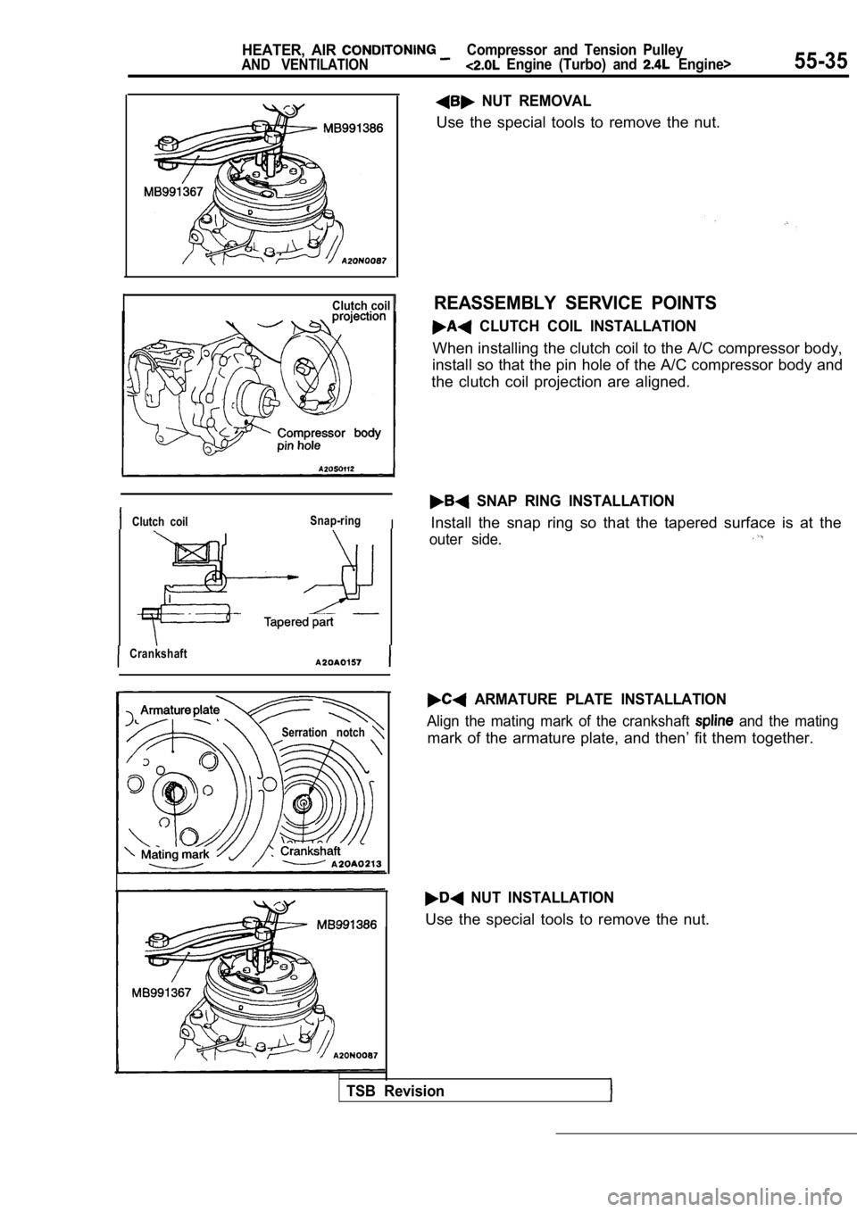
NUT REMOVAL
Use the special tools to remove the nut.
REASSEMBLY SERVICE POINTS
CLUTCH COIL INSTALLATION
When installing the clutch coil to the A/C compress
or body,
install so that the pin hole of the A/C compressor body and
the clutch coil projection are aligned.
SNAP RING INSTALLATION
Install the snap ring so that the tapered surface i s at the
outer side.
ARMATURE PLATE INSTALLATION
Align the mating mark of the crankshaft and the mating
mark of the armature plate, and then’ fit them toge ther.
NUT INSTALLATION
Use the special tools to remove the nut.
TSB Revision
Page 2078 of 2103
55-38HEATER, AIR
AND VENTILATION Compressor and Tension Pulley Engine (Non-turbo)>
COMPRESSOR AND TENSION PULLEY ENGINE
REMOVAL AND INSTALLATION
Pm-removaland Post-installation Operation Refrigerant Discharging and Charging(Refer to (2) Under Cover Removal and Installation(Refer to GROUP 42 Under Cover.)
(3) Compressor Drive Belt Adjustment
(Refer to GROUP
On-vehicle Service.)
CAUTIONPlug refrigerant lines to prevent from when disconnecting them.I
H o s e c o n n e c t i o n
Compressor oil: ND-OIL 8
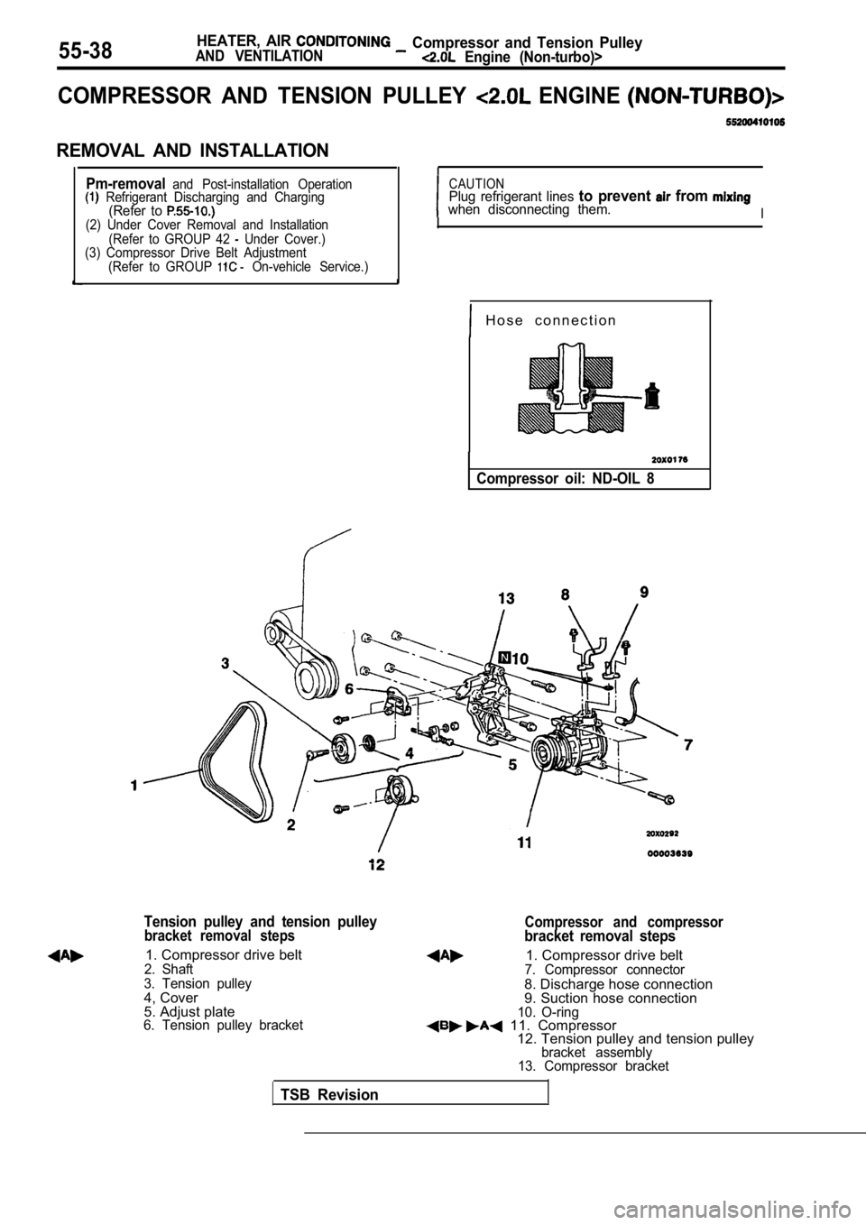
Tension pulley and tension pulley
bracket removal steps
1. Compressor drive belt2. Shaft
3. Tension pulley
4, Cover
5. Adjust plate
6. Tension pulley bracket
Compressor and compressorbracket removal steps
1. Compressor drive belt7. Compressor connector
8. Discharge hose connection
9. Suction hose connection
10. O-ring 11. Compressor 12. Tension pulley and tension pulley
bracket assembly
13. Compressor bracket
TSB Revision
Page 2079 of 2103
Compressor
AND VENTILATION,
REMOVAL SERVICE
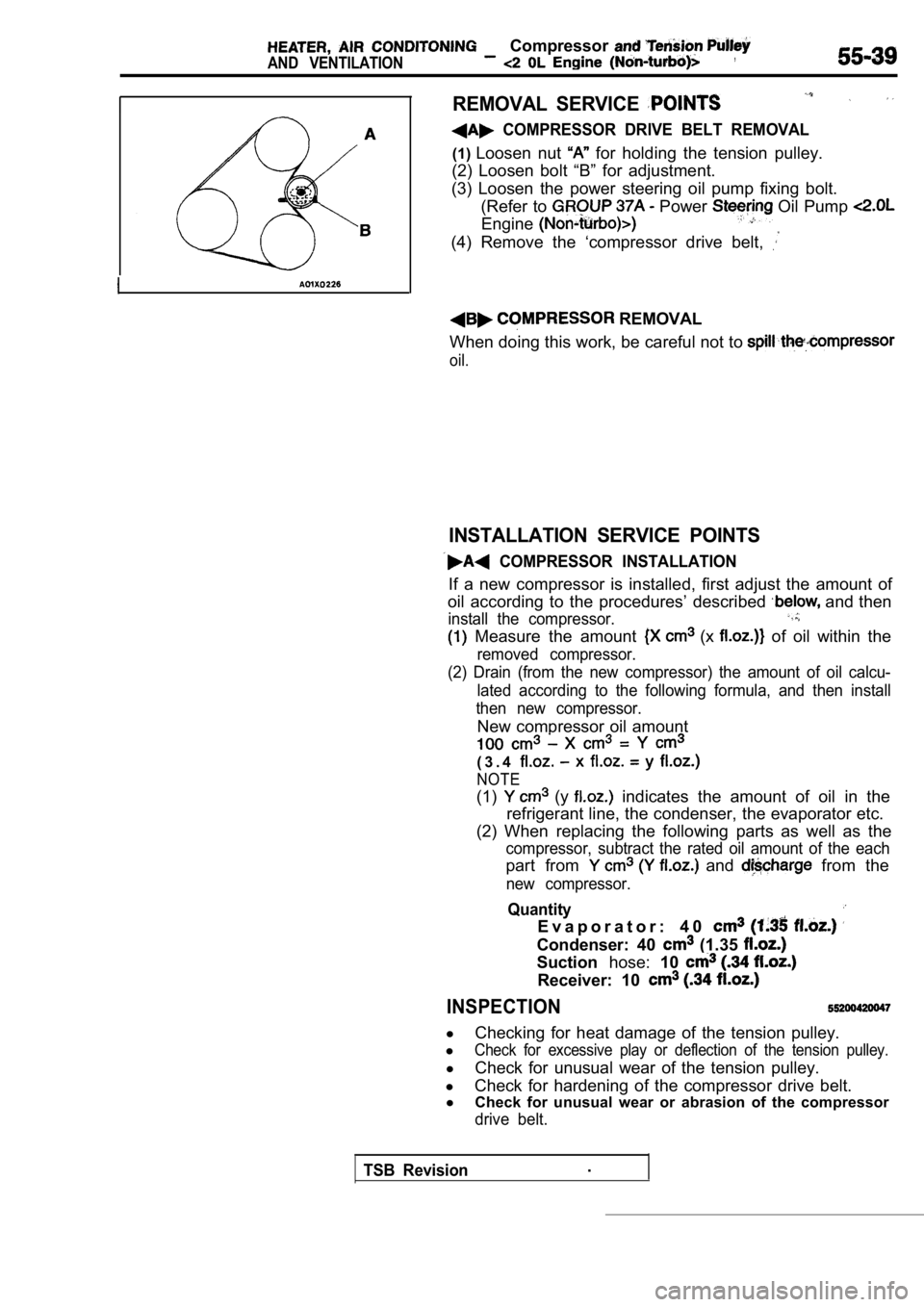
COMPRESSOR DRIVE BELT REMOVAL
(1)Loosen nut for holding the tension pulley.
(2) Loosen bolt “B” for adjustment.
(3) Loosen the power steering oil pump fixing bolt. (Refer to
Power Oil Pump
Engine
(4) Remove the ‘compressor drive belt,
REMOVAL
When doing this work, be careful not to
oil.
INSTALLATION SERVICE POINTS
COMPRESSOR INSTALLATION
If a new compressor is installed, first adjust the amount of
oil according to the procedures’ described
and then
install the compressor.
Measure the amount (x of oil within the
removed compressor.
(2) Drain (from the new compressor) the amount of o il calcu-
lated according to the following formula, and then install
then new compressor.
New compressor oil amount
( 3 . 4
NOTE
(1) (y indicates the amount of oil in the
refrigerant line, the condenser, the evaporator etc .
(2) When replacing the following parts as well as t he
compressor, subtract the rated oil amount of the each
part from and from the
new compressor.
Quantity
E v a p o r a t o r : 4 0
Condenser: 40 (1.35
Suctionhose:10
Receiver: 10
INSPECTION
l
Checking for heat damage of the tension pulley.
l
Check for excessive play or deflection of the tensi on pulley.
l
Check for unusual wear of the tension pulley.
l Check for hardening of the compressor drive belt.
l Check for unusual wear or abrasion of the compresso r
drive belt.
TSB Revision.
Page 2085 of 2103
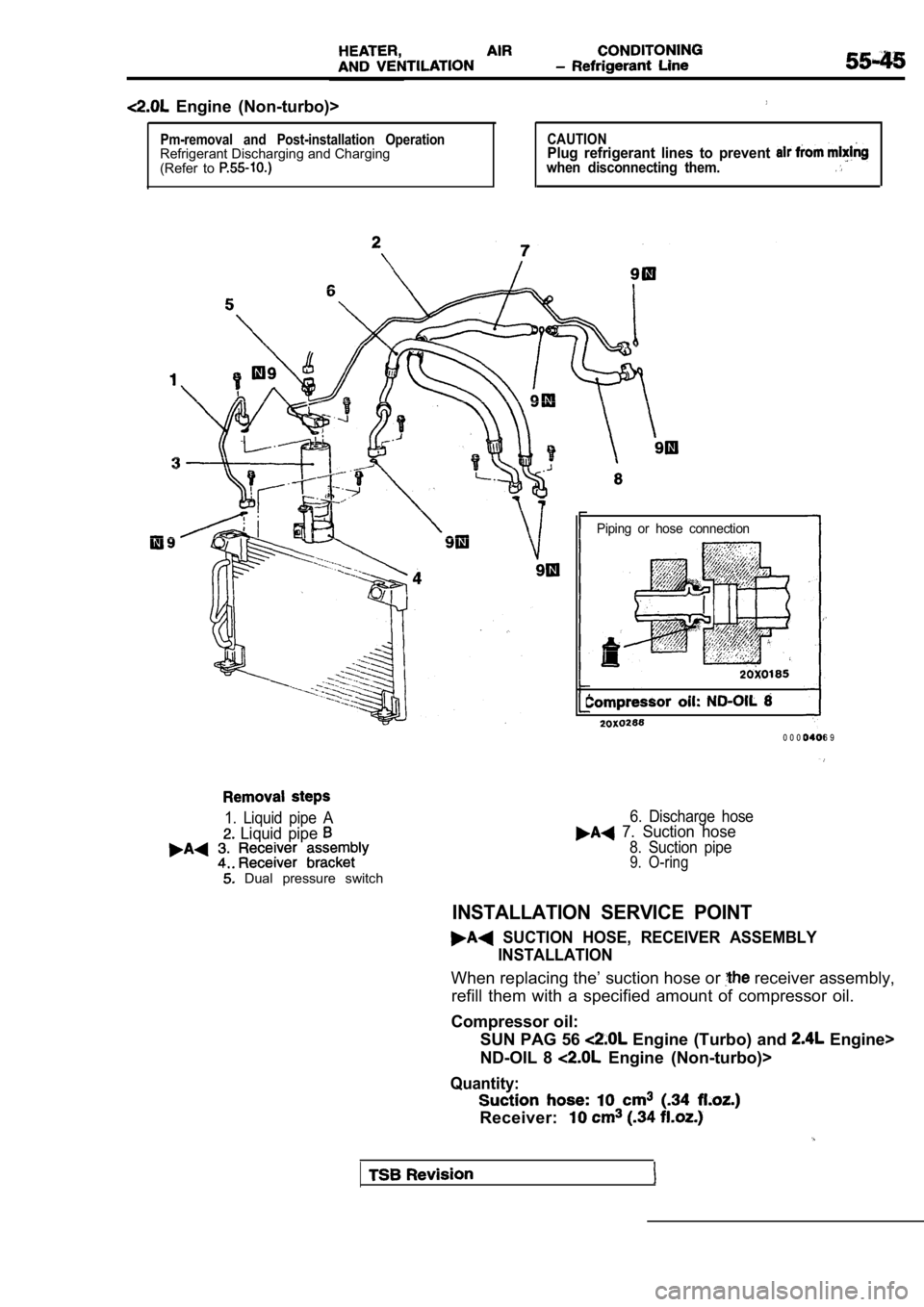
Engine (Non-turbo)>
Pm-removal and Post-installation OperationRefrigerant Discharging and Charging
(Refer to CAUTIONPlug refrigerant lines to prevent when disconnecting them.
Piping or hose connection
0 0 0 0 4 0 6 9
1. Liquid pipe A
Liquid pipe
Dual pressure switch
6. Discharge hose 7. Suction hose
8. Suction pipe9. O-ring
INSTALLATION SERVICE POINT
SUCTION HOSE, RECEIVER ASSEMBLYINSTALLATION
When replacing the’ suction hose or receiver assembly,
refill them with a specified amount of compressor o il.
Compressor oil: SUN PAG 56
Engine (Turbo) and Engine>
ND-OIL 8
Engine (Non-turbo)>
Quantity:
Receiver:
Page 2088 of 2103
HEATER, AIR Condenser and
Condenser Fan’ Motor
TurboNon-turbo
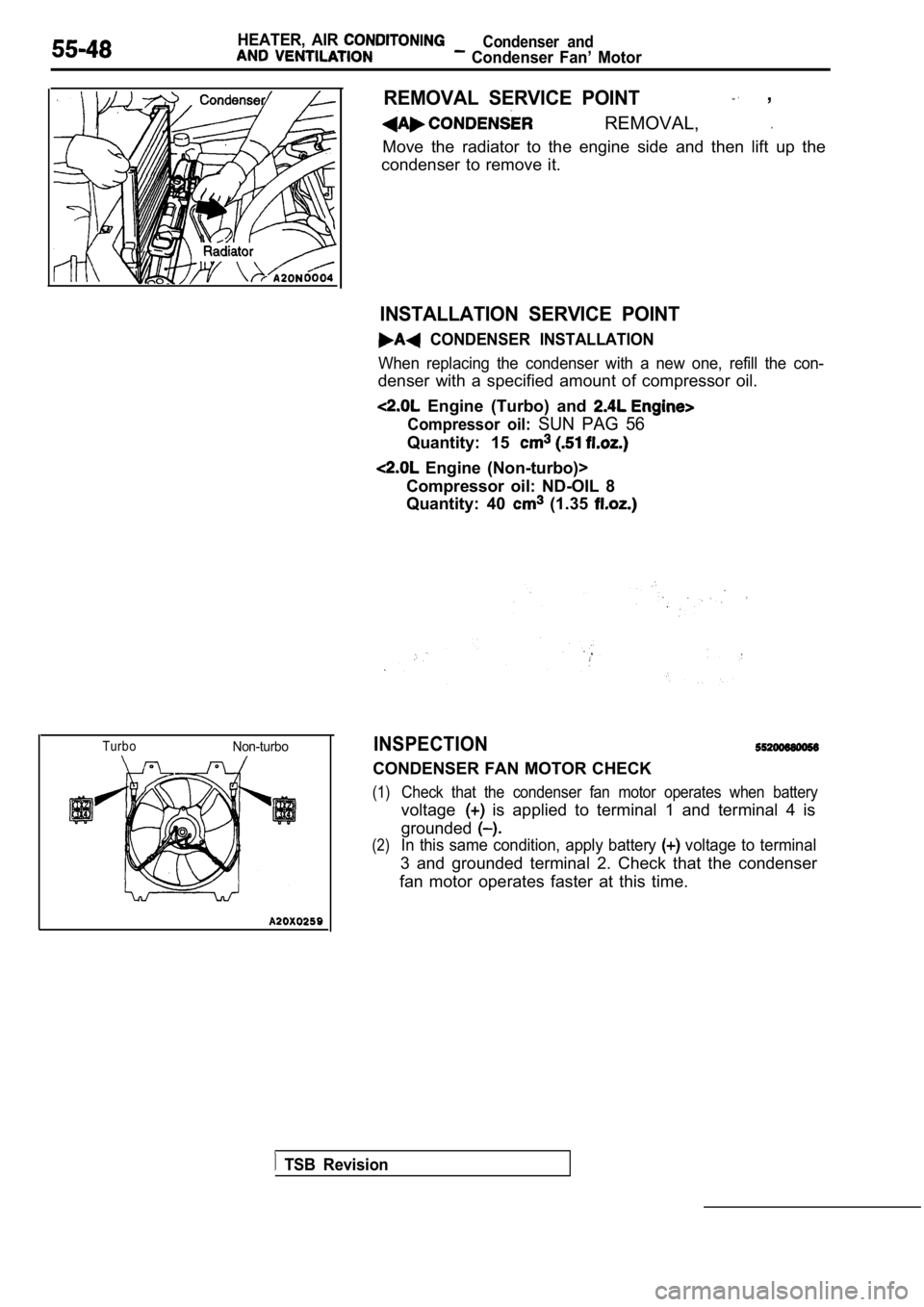
REMOVAL SERVICE POINT ,
REMOVAL,
Move the radiator to the engine side and then lift up the
condenser to remove it.
INSTALLATION SERVICE POINT
CONDENSER INSTALLATION
When replacing the condenser with a new one, refill the con-
denser with a specified amount of compressor oil.
Engine (Turbo) and
Compressor oil: SUN PAG 56
Quantity: 15
Engine (Non-turbo)>
Compressor oil: ND-OIL 8
Quantity: 40
(1.35
INSPECTION
CONDENSER FAN MOTOR CHECK
(1)Check that the condenser fan motor operates when ba ttery
voltage is applied to terminal 1 and terminal 4 is
grounded
(2)In this same condition, apply battery voltage to terminal
3 and grounded terminal 2. Check that the condenser
fan motor operates faster at this time.
TSB Revision
Page 2090 of 2103
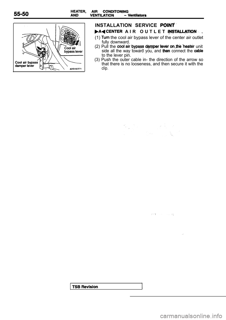
INSTALLATION SERVICE
A I R O U T L E T
(1) the cool air bypass lever of the center air outlet
fully downward.
(2) Pull the unit
side all the way toward you, and connect the
to the lever pin.
(3) Push the outer cable in- the direction of the a rrow so
that there is no looseness, and then secure it with the
clip.
Page 2101 of 2103
ALPHABETICAL, INDEX
ENGINE (TURBO) AND ENGINE>. . . . . . .
Intake Air Temperature, On-vehicle ENGINE (NON-TURBO)> . . . . . . . . . . . . . .
ENGINE (TURBO) AND . . , .
Throttle Position, Adjustment ENGINE (TURBO) AND ENGINE> . . . .
Throttle Position, On-vehicle Inspection ENGINE (NON-TURBO)> . . . . . . . . . . . . . ENGINE (TURBO) AND ENGINE>. . .
Volume Air Flow ENGINE (TURBO) AND ENGINE> . . . . . . . . . . . . . . . . . . . . . . . . . . . .
Wheel Speed
. . . . . . . . . . . . . . . . . . . . .
SERVO,
. . . . . . . . .
. . . . . . . . . . . . . . . . . .
Adjustment ENGINE (TURBO) AND ENGINE> . . . . . . . . . . . . . . . . . . . . . .
SHAFT
Counterbalance. . . . . . . . . . . . . . . . . . . . . . .11Drive. . . . . . . . . . . . . . . . . . . . . . . . . . . . . . . .
. . . . . . . . . . . . . . . . . . . . . . . . . . . . . . . . .
. . . . . . . . . . . . . . . . . . . . . . . . . . . . . . . . . . . . . .
Front Output . . . . . . . . . . . . . . . . . . . . . . . . . .
. . . . . . . . . . . . . . . . . . . . . . . . . . .
Input, Disassembly . . . . . . . . . . . . . . . . . . . . . .
. . . . . . . . . . . . . . . . . . . . . . . . . . . .
. . . . . . . . . . . . .
Propeller. . . . . . . . . . . . . . . . . . . . . . . . . . . . . . . . . . . . . . . . . . .
Output. . . . . . . . . . . . . . . . . . . . . . . . . .
Steering. . . . . . . . . . . . . . . . . . . . . . . . . . . . . . . . . . . . . . . . .
Transfer. . . . . . . . . . . . . . . . . . . . . . . . . . . . . . . .
. . . . . . . . . . . . . . . . . . . . . . . . . . . . . . .
SHIFT. . . . . . . . . . . . . . . .
SHIFT LOCK MECHANISM
Check
ENGINE (NON-TURBO)>. . . . . . . . . . . .
ENGINE (TURBO) AND ENGINE> .
SHIFTER RAILS, Overhaul . . . . . . . . . . . . . . . . . .
SHOCK ABSORBER
SIGHT GLASS REFRIGERANT LEVEL, Test. . . . . . . . . . . . . . .
SOLENOID On-vehicle Inspection ENGINE (TURBO) AND ENGINE>. . . . . . . . . . . . . . . . . . . . . . . . . . . . . . . . . .
Electric EGR Transducer, Check ENGINE (NON-TURBO)>. . . . . . . . . . . . . . . . . . . . . .
Electric EGR Transducer, On-vehicle ENGINE (NON-TURBO)>. . . . . . . . . . . . . . . . . . .
Evaporative Emission Pur ENGINE (NON- Check. . . . . . . . . . . . . . . . . . .
ENGINE (TURBO) AND ENGINE>. . . . . . .
Evaporative Emission Pur On-vehicle Inspection ENGINE (NON-. . . . . . , . . .
E N G I N E A N D . .
Evaporative . . . . . . . . . . . . . . . . . .
Fuel Pressure, On-vehicle Inspection (TURBO)>. . . . . . . . . . . . . . . .
Turbocharger Waste Gate, Check . . . . . . . . . . . .
Turbocharger Waste Gate, On-vehicle Inspection ENGINE (TURBO)> . . . . . . . . . . . . . . . . . .
SPARK COIL, Test ENGINE (NON-TURBO)> . . . . .
SPARK PLUG
Check ENGINE (NON-TURBO)> . . . . . . . . .
ENGINE (TURBO) AND ENGINE> . . Gleaning ENGINE (NON-TURBO)=.. . . . . . . . . .
ENGINE (TURBO) AND ENGINE>
Test ENGINE (NON-TURBO)> . . . . . . . . . . . . . . . .
ENGINE (TURBO) AND ENGINE> . . , .
SPARK PLUG CABLE, Resistance Check ENGINE . . . . . . . . . . . . . . . . . . . . . .
SPARK PLUG CABLE, Resistance ENGINE (TURBO) AND ENGINE>. . . . . . . . . .
SPARK PLUG CABLE, Test ENGINE (TURBO) AND ENGINE> . . . . . . . . . . . . . . . . . . . . . . . . . . . . . . . . .
SPARK PLUGS, Maintenance . . . . . . . . . . . . . . . . . . . . . . . . . . . SPEAKER . . . . . .. . . . . . . . . . . . . . . . . . . . . . . . . .
. ..*......
SPECIFICATIONS, Pressure Check ENGINE (NON-TURBO)> . . . . . . . . . . . . . . . . . . . . SPEEDOMETER, Check. . . . . . . . . . . . . . . . . . . . . . . . . . . . . . .
SPEEDOMETER GEAR. . . . . . . . . . . . . . . . . . . . . . . . . . . . . . . . .. . . . . . . . . . . . . . . . . . . . . . . . .
. . . . . . . . . . . . . . . . . . . . . . . . . . . . . . . . . . . . . . . .
SRS AIR BAG CONTROL UNIT (SRS-ECU). . . . . . . . . . . .
SERVICE . . . . . . . . . . . . . . . . . . . . . . .
SRS SYSTEM, Maintenance. . . . . . . . . . . . . . . . . . .. . . . . .STABILIZER BAR
STARTER MOTOR ENGINE (NON-TURBO)>. . . . . . . . . . . . . . . . . .
ENGINE (TURBO) AND ENGINE>.. . . . . . . .
STARTING SYSTEM E N G I N E . . . . . . . . . . . . . . . . . . . . . .
ENGINE ENGINE>... . . . .
STATIONARY STEERING EFFORT, Check. . . . . . . . . . . . . . .
STEERING Check. . . . . . . . . . . . . . . . . . . . . . . . .
STEERING LINKAGE SEALS, Maintenance. . . . . . . . . . . . . .. . . . . . . . . . . . . . . . . . . . . . . . . . . . . . . . . .
STEERING WHEEL. . . . . . . . . . . . . . . . . . . . . . . . . . . ..
. . . .STEERING WHEELFree Play Check. . . . . . . . . . . . . . . . . . . . . . . . . . . . . . . . . .
Return to Center, Check. . . . . . . . . . . . . . . . . . . . . . . . . . . .
STEERINGAngle Check. . . . . . . . . . . . . . . . . . . . . . . . . . . . . . . . . . . . . . .
Stationary Effort Check. . . . . . . . . . . . . . . . . . . . .. . . . . . .
STOP LIGHT SWITCH, Check. . . . . . . . . . . . . . . . . . . . . . ....
STOPPER, Roll, Engine. . . . . . . . . . . . . . . . . . . . . . . . . . . . . . . . . . .
SUNROOF. . . . . . . . . . . . . . . . . . . . . . . .. . . . . . . . . . . . . . . . . .
SUSPENSION, Rear. . . . . . . . . . . . . . . . . . . . . . . . . . . . . . . . . . . . .
SWITCHAir Conditioning. . . . . . . . . . . . . . . . . . . . . . . . . . . . . . . ...
ENGINE (NON-TURBO)>. . . . . . . . . . . . . . . . . . .
ENGINE (TURBO) AND ENGINE> . . . . .
Closed Adjustment ENGINE
(TURBO) AND ENGINE>. . . . . . . . . . . . . . , . . .
Closed Position, On-vehicle Ins ENGINE (TURBO) AND EN . . . . . top. . . . . . . . . . . . .. . . . . . . . . . . . . .. . . . . .
Convertible top, bypass. . . . . . . . . . . . . . . . . . . . . . . . . . . .
Defogger, Rear Window. . . . . . . . . . . . . . . . . . . . . . . . . . . .
Dual Pressure, Check. . . . . . . . . . . . . . . . . . . . . . . . . . . . . . . .
Hazard Warning Light. . . . . . . . . . . . . . . . . . . . . . . . . . . . . .
Ignition. . . ... . . . . . . . . . . . . . . . . . . . . . . . . . . . . . . . .. . . . . .Interlock, Check and . . . . . . . .. . . . . . . . . .
Operating Check.. . . . . . . . . . . . . . . . . . . . . . . . .
Parking Brake, Check. . . . . . . . . . . . . . . . . . . . . . . . . . . . . . . .
Power Steering Pressure, Check. . . . . . . . . . . . . . . . . . .
Stop Light, Check. . . . . . . . . . . . . . . . . . . . . . . . . . . . . . . .
SYNCHRONIZER. . . . . . . . . . . . . . .
Overhaul. . . . . . . . . . . . . . . . . . . . . . . . . . . . . . .
TACHOMETER, Check. . . . . . . . . . . . . . . . . . . . . . . . . . . . . . . .
ITAPE PLAYER. . . . . . . . . . . . . . . . . . . . . . . . . . . . . . . . . . . . . . . .