Page 2027 of 2103
SRS Post-collision Diagnosis/Component Service
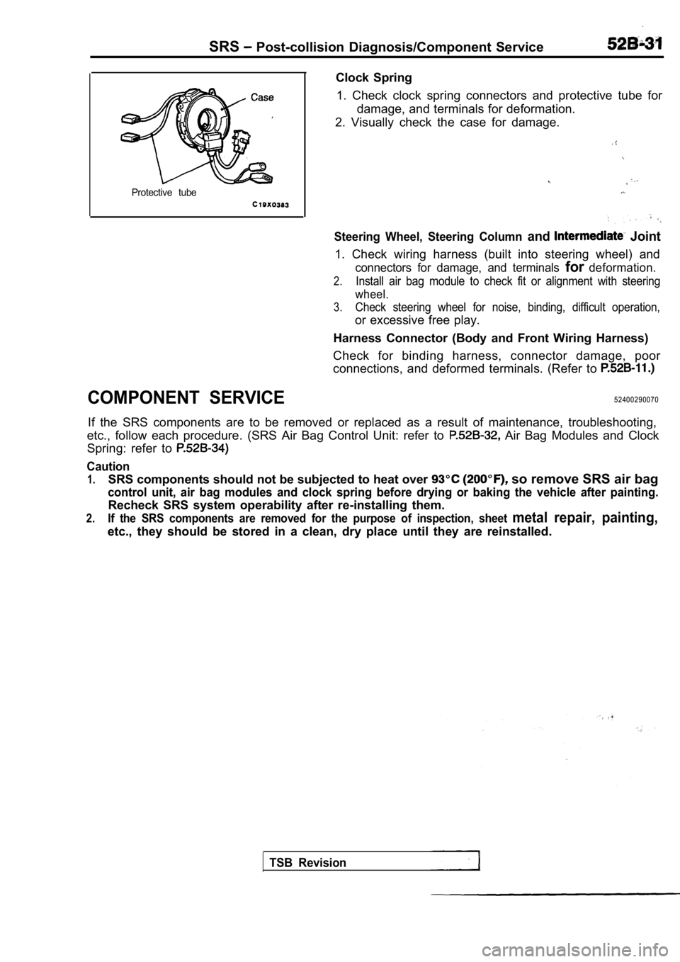
Protective tube
COMPONENT SERVICE
Clock Spring1. Check clock spring connectors and protective tub e for
damage, and terminals for deformation.
2. Visually check the case for damage.
Steering Wheel, Steering Column and Joint
1. Check wiring harness (built into steering wheel) and
connectors for damage, and terminals fordeformation.
2.Install air bag module to check fit or alignment with steering
wheel.
3.Check steering wheel for noise, binding, difficult operation,
or excessive free play.
Harness Connector (Body and Front Wiring Harness)
Check for binding harness, connector damage, poor
connections, and deformed terminals. (Refer to
52400290070
If the SRS components are to be removed or replaced as a result of maintenance, troubleshooting,
etc., follow each procedure. (SRS Air Bag Control U nit: refer to
Air Bag Modules and Clock
Spring: refer to
Caution
1.SRS components should not be subjected to heat over so remove SRS air bag
control unit, air bag modules and clock spring before drying or baking the vehicle after painting.
Recheck SRS system operability after re-installing them.
2.If the SRS components are removed for the purpose o f inspection, sheet metal repair, painting,
etc., they should be stored in a clean, dry place until they are reinstalled.
TSB Revision
Page 2029 of 2103
SRS SRS Air BagControl Unit (SRS-ECU)
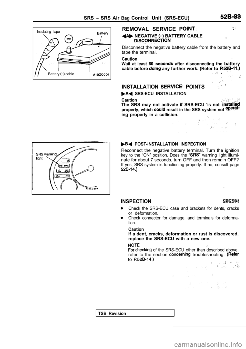
Insulating tape
Battery cable
REMOVAL SERVICE
NEGATIVE BATTERY CABLE
.
Disconnect the negative battery cable from the batt ery and
tape the terminal.
Caution
Wait at least 60 after disconnecting the battery
cable before any further work. (Refer to ,
INSTALLATION POINTS.
SRS-ECU INSTALLATION
Caution
The SRS may not activate SRS-ECU ‘is not
properly, which result in the SRS system not
ing properly in a collision.
POST-INSTALLATION INSPECTION
Reconnect the negative battery terminal. Turn the i gnition
key to the “ON” position. Does the warning light illumi-
nate for about 7 seconds, turn OFF and then remain OFF?
If yes, SRS system is functioning properly. If no, consult page
INSPECTION52400220045
Check the SRS-ECU case and brackets for dents, crac ks
or deformation.
Check connector for damage, and terminals for defor ma-
tion.
Caution
If a dent, cracks, deformation or rust is discovered,
replace the SRS-ECU with a new one.
of the SRS-ECU other than described above,
refer to the section troubleshooting.
to,
TSB Revision
Page 2031 of 2103
SRS Air Bag Modules and Clock Spring
bag module (Front passenger’s side)>.
Air bag module (Front passenger’s side)
removal steps
Post-installation inspection
1. Negative battery cable connection
7. Air bag module (Front passenger’s side)
Pre-installation inspection
Insulating tape
Al 920001
REMOVAL SERVICE POINTS
C A B L E
DISCONNECTION
Disconnect the negative battery cable from the batt ery and
tape the terminal.
Caution
Wait at least 60 seconds after disconnecting the ba ttery
cable before doing any further work. (Refer to
BAG MODULE (DRIVER’S REMOVAL
(1) Remove the airbag module mounting nut using socket
wrench from the back side.
(2) When disconnecting the connector of the
spring
from the air bag module, press the air bag’s look t oward
the outer side to spread open. Use a flat-tipped
screwdriver, as shown in the figure at the left; to pry
so as to remove the connector gently.
TSB Revision
Page 2032 of 2103
SRS Air Bag Modules and Clock Spring
Caution
1. When disconnecting the air bag module-clock
spring connector, take care not to apply excessive
force to it.
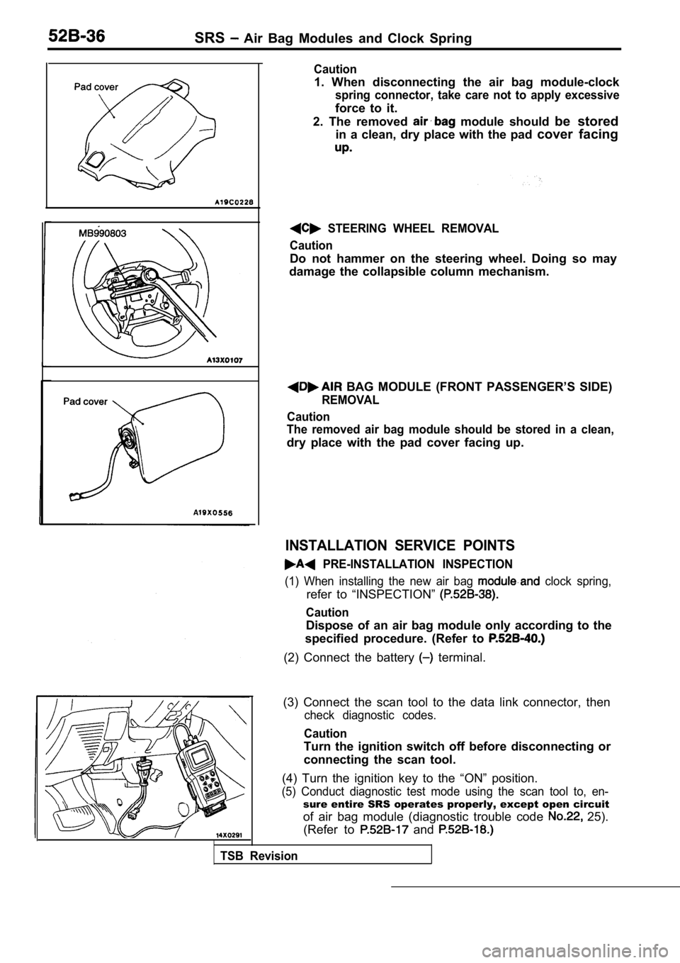
2. The removed
module should be stored
in a clean, dry place with the pad cover facing
STEERING WHEEL REMOVAL
Caution
Do not hammer on the steering wheel. Doing so may
damage the collapsible column mechanism.
BAG MODULE (FRONT PASSENGER’S SIDE)
REMOVAL
Caution
The removed air bag module should be stored in a cl ean,
dry place with the pad cover facing up.
INSTALLATION SERVICE POINTS
PRE-INSTALLATION INSPECTION
(1) When installing the new air bag clock spring,
refer to “INSPECTION”
Caution
Dispose of an air bag module only according to the
specified procedure. (Refer to
(2) Connect the battery terminal.
(3) Connect the scan tool to the data link connecto r, then
check diagnostic codes.
Caution
Turn the ignition switch off before disconnecting o r
connecting the scan tool.
(4) Turn the ignition key to the “ON” position.
(5) Conduct diagnostic test mode using the scan too l to, en-
sure entire SRS operates properly, except open circuit
of air bag module (diagnostic trouble code
25).
(Refer to
and
TSB Revision
Page 2041 of 2103
CONTENTS
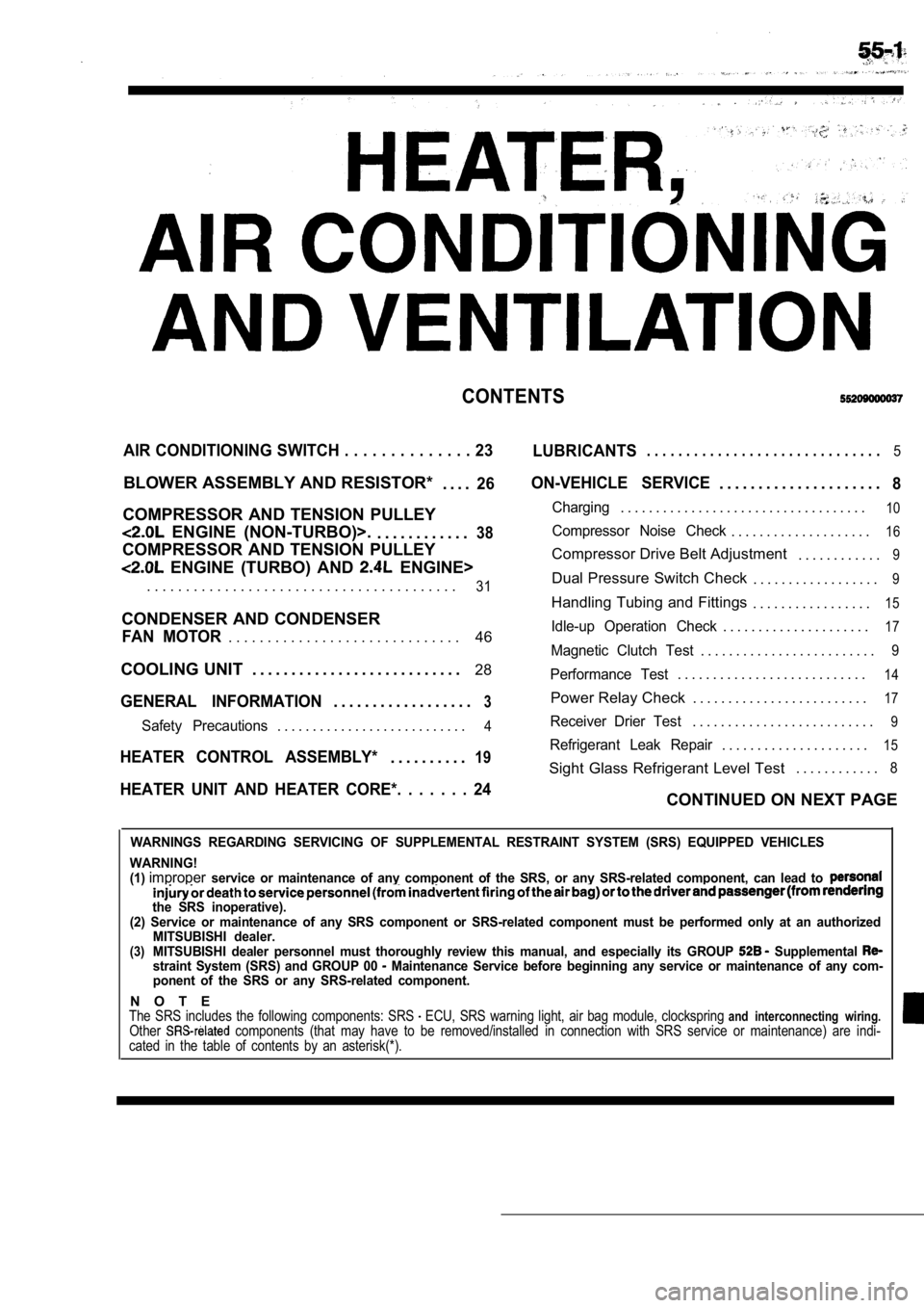
AIR CONDITIONING SWITCH . . . . . . . . . . . . . . 23
LUBRICANTS. . . . . . . . . . . . . . . . . . . . . . . . . . . . . .5
BLOWER ASSEMBLY AND RESISTOR*
. . . .26
COMPRESSOR AND TENSION PULLEY
ENGINE (NON-TURBO)>.. . . . . . . . . . . .38
COMPRESSOR AND TENSION PULLEY
ENGINE (TURBO) AND ENGINE>
ON-VEHICLE SERVICE. . . . . . . . . . . . . . . . . . . . .8
Charging. . . . . . . . . . . . . . . . . . . . . . . . . . . . . . . . . . .10
Compressor Noise Check. . . . . . . . . . . . . . . . . . . .16
Compressor Drive Belt Adjustment . . . . . . . . . . . .9
. . . . . . . . . . . . . . . . . . . . . . . . . . . . . . . . . . . . . . . .31Dual Pressure Switch Check. . . . . . . . . . . . . . . . . .9
Handling Tubing and Fittings. . . . . . . . . . . . . . . . .15
CONDENSER AND CONDENSER
46Idle-up Operation Check. . . . . . . . . . . . . . . . . . . . .17FAN MOTOR. . . . . . . . . . . . . . . . . . . . . . . . . . . . . .Magnetic Clutch Test. . . . . . . . . . . . . . . . . . . . . . . . .9
COOLING UNIT . . . . . . . . . . . . . . . . . . . . . . . . . . . 28
GENERAL INFORMATION3. . . . . . . . . . . . . . . . . .
Performance Test. . . . . . . . . . . . . . . . . . . . . . . . . . .14
Power Relay Check . . . . . . . . . . . . . . . . . . . . . . . . .17
Safety Precautions. . . . . . . . . . . . . . . . . . . . . . . . . . .4Receiver Drier Test. . . . . . . . . . . . . . . . . . . . . . . . . .9
. . . . . . . . . . . . . . . . . . . . .15HEATER CONTROL ASSEMBLY*19Refrigerant Leak Repair. . . . . . . . . .
Sight Glass Refrigerant Level Test . . . . . . . . . . . .8
HEATER UNIT AND HEATER CORE*. . . . . . . 24CONTINUED ON NEXT PAGE
WARNINGS REGARDING SERVICING OF SUPPLEMENTAL RESTRA
INT SYSTEM (SRS) EQUIPPED VEHICLES
WARNING!
(1)
improperservice or maintenance of any component of the SRS, or any SRS-related component, can lead to
the SRS inoperative).
(2) Service or maintenance of any SRS component or SRS-related component must be performed only at an authorized
MITSUBISHI dealer.
(3)MITSUBISHI dealer personnel must thoroughly review this manual, and especially its GROUP Supplemental straint System (SRS) and GROUP 00 Maintenance Service before beginning any service or maintenance of any com-
ponent of the SRS or any SRS-related component.
N O T EThe SRS includes the following components: SRS ECU, SRS warning light, air bag module, clocksprin g and interconnecting wiring.Other components (that may have to be removed/installed in connection with SRS service or maintenance) are indi-
cated in the table of contents by an asterisk(*).
Page 2042 of 2103
55-2
REFRIGERANT LINE. . . . . . . . . . . . . . . . . . . . . .44 OUTLET). .. . . . . . .
SERVICE SPECIFICATIONS. . . . . . . . . . . . . . . . .VENTILATORS* (FLOOR). . . . . . . . . . . . . . . . .
SPECIAL TOOLS. . . . . . . . . . . . . . . . . . . . . . . . . . .5 (INSTRUMENT PANEL) . . .
TROUBLESHOOTING . . . . . . . . . . . . . . . . . . . . . . . 6
Page 2045 of 2103

HEATER, AIR Service
AND VENTILATION Special Tools
SERVICE SPECIFICATIONS
IStandard value ‘I
speed E n g i n e ( T u r b o ) a n d
EngineII
Engine (Non-turbo)I
up speed
Resistor (for blower motor) LO
100 in Neutral
1.83
MHI 0.31
Revolution pick up sensor standard resistance
Engine (Non-turbo)>
185
[when ambient temperature is
Refrigerant temperature switch ON (continuity) tempe rature
Engine (Turbo) and
Engine>OFF (no continuity) temperature
Approx. or less
Approx. or more
(until the temperature drops to approx.
when OFF)
Air gap (Magnetic clutch) mm (in.)
Engine (Turbo) and
Engine
Engine (Non-turbo)I
LUBRICANTS
ItemsSpecified lubricants Quantity
Each connection of refrigerant line ND-OIL 8 Engine (Non-turbo)>, SUN PAG 56 As required
Engine (Turbo) and Engine>
Lip seal of the compressor ND-OIL 8
Engine (Non-turbo)>As required
Compressor refrigerant unit lubricant SUN PAG 56
lubricant
Engine (Turbo) and Engine>
ND-OIL 8
Engine (Non-turbo)>
SPECIAL TOOLS
ToolTool number and nameSupersession Application
367Armature mounting nut of com-
e S p e c i a l s p a n n e r removal and installation
Engine (Turbo) and
Engine>
386
Pin
TSB Revision
Page 2048 of 2103
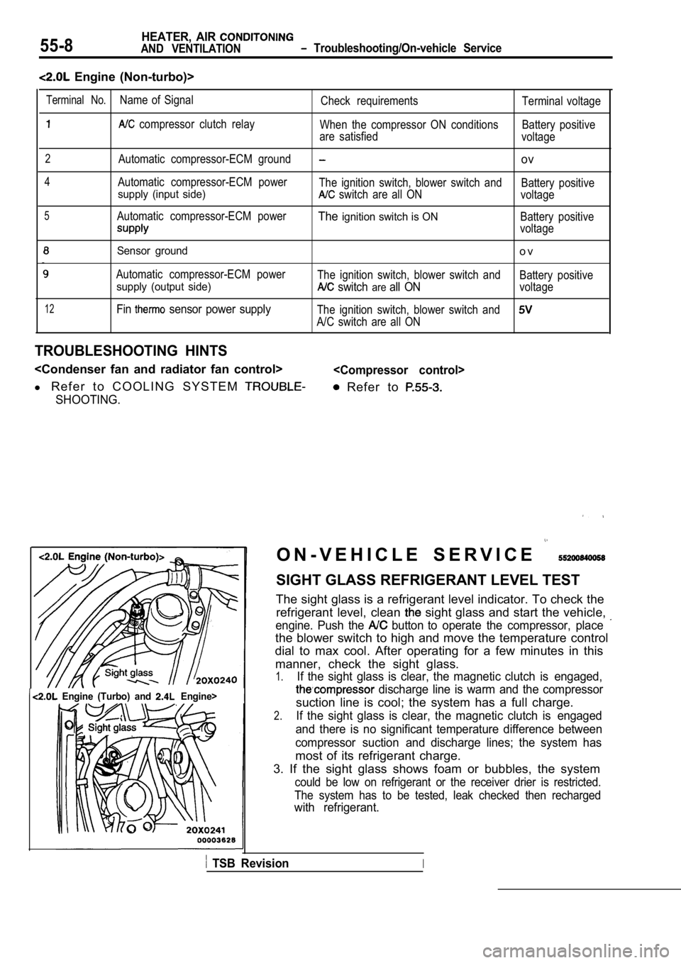
55-8HEATER, AIR
AND VENTILATION Troubleshooting/On-vehicle Service
Engine (Non-turbo)>
12
Sensor ground
Automatic compressor-ECM power
supply (output side)
Fin sensor power supply
o v
The ignition switch, blower switch andBattery positive
switch areall ONvoltage
The ignition switch, blower switch and
A/C switch are all ON
TROUBLESHOOTING HINTS
l R e f e r t o C O O L I N G S Y S T E M
SHOOTING.
Refer to
Terminal No.Name of Signal
Check requirements Terminal voltage
compressor clutch relay
When the compressor ON conditions Battery positive
are satisfied voltage
2Automatic compressor-ECM groundov
4Automatic compressor-ECM power
The ignition switch, blower switch and Battery positive
supply (input side) switch are all ONvoltage
5Automatic compressor-ECM powerTheignition switch is ONBattery positive
voltage
Engine (Turbo) and Engine>I
O N - V E H I C L E S E R V I C E
SIGHT GLASS REFRIGERANT LEVEL TEST
The sight glass is a refrigerant level indicator. T o check the
refrigerant level, clean
sight glass and start the vehicle,
engine. Push the button to operate the compressor, place
the blower switch to high and move the temperature control
dial to max cool. After operating for a few minutes in this
manner, check the sight glass.
1.If the sight glass is clear, the magnetic clutch is engaged,
discharge line is warm and the compressor
suction line is cool; the system has a full charge.
2.If the sight glass is clear, the magnetic clutch is engaged
and there is no significant temperature difference between
compressor suction and discharge lines; the system has
most of its refrigerant charge.
3. If the sight glass shows foam or bubbles, the sy stem
could be low on refrigerant or the receiver drier is restricted.
The system has to be tested, leak checked then rech arged
with refrigerant.
TSB RevisionI