Page 1931 of 2103
E X T E R I O R
CONTENTS
AERO PARTS. . . . . . . . . . . . . . . . . . . . . . . . . . . . .11REAR BUMPER. . . . . . . . . . . . . . . . . . . . . . . . . . .4
Aero Parts . . . . . . . . . . . . . . . . . . . . . . . . . . . . . . . . . .
11REAR WIPER AND WASHER . . . . . . . . . . . . .20Sealant and Adhesive . . . . . . . . . . . . . . . . . . . . . . . .11General Information. . . . . . . . . . . . . . . . . . . . . . . . .20
DOOR MIRROR. . . . . . . . . . . . . . . . . . . . . . . . . . . 25Rear Wiper and ‘Washer. . . .. . . . . . . . . . . . . . . . .21
Door Mirror . . . . . . . . . . . . . . . . . . . . . . . . . . . . . . . . .25Service ‘Specification. . . . . . . . . . . . . . . . . . . . . . . .20
Special Tool . . . . . . . . . . . . . . . . . . . . . . . . . . . . . . . .
25Troubleshooting. . . . . . . . . . . . . . . . . . . . . . . . . . . . .20
FRONT BUMPER. . . . . . . . . . . . . . . . . . . . . . . . .2WINDSHIELD WIPER AND WASHER* . . . . . .13
6General Information. . . .. . . . . . . . . . . . . . . . . . . .13GARNISHES. . . . . . . . . . . . . . . . . . . . . . . . . . . . . .Service Specification. . . . . . . . . . . . . . . . . . . . . . . .13
MOLDINGS. . . . . . . . . . . . . . . . . . . . . . . . . . . . . . .7Troubleshooting. . . . . . . . . . . . . . . . . . . . . . . . . . . . .14
Molding. . . . . . . . . . . . . . . . . . . . . . . . . . . . . . . . . . . . .7Windshield Wiper and Washer . . .. . . . . . . . . .15
Sealant and Adhesive . . . . . . . . . . . . . . . . . . . . . . . .7
WARNINGS REGARDING SERVICING OF SUPPLEMENTAL RESTRA INT SYSTEM (SRS) EQUIPPED VEHICLES
WARNING! (1)
Improper service or maintenance of anycomponentof the SRS, or any SRS-related component, can lead to personalinjury or death to personnel (from inadvertent firing of the air bag) the the SRS inoperative). Service or maintenance of any SRS component or SRS -related component must be performed only at an authorized. MITSUBISHI dealer.(3) MITSUBISHI dealer personnel must thoroughly rev iew this manual, and especially its Supplemental
Restraint System (SRS) and GROUP 00 Maintenance Service, before beginning any service or maintenance of any
component of the SRS or any SRS-related component.
NOTE
The includes the following components: warning light, air bag module, and interconnecting wiring.Other components (that may have to be removed/installed in connection with service or maintenance) areindicated in the table of contents by an asterisk
Page 1939 of 2103
E X T E R I O R Moldings:
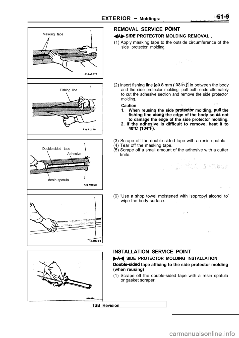
Masking tape
Fishing line
Double-sided tape
Adhesive
desin spatula
REMOVAL SERVICE
PROTECTOR MOLDING REMOVAL ,
(1) Apply masking tape to the outside circumference of the
side protector molding.
(2) insert fishing line mm in between the body
and the side protector molding, pull both ends alternately
to cut the adhesive section and remove the side pro tector
molding.
Caution
1.When reusing the side molding, the
fishing line the edge of the body so not
to damage the edge of the side protector molding.
2. If the adhesive is difficult to remove, heat it to
(3) Scrape off the double-sided tape with a resin spatula.
(4) Tear off the masking tape. (5) Scrape off a small amount of the adhesive with a cutter
knife.
(6) ‘Use a shop towel moistened with isopropyl alco hol to’
wipe the body surface.
INSTALLATION SERVICE POINT
SIDE PROTECTOR MOLDING INSTALLATION
tape affixing to the side protector molding
(when reusing)
(1) Scrape off the double-sided tape with a resin s patula
or gasket scraper.
TSB Revision
Page 1942 of 2103
EXTERIOR Aero Parts
High Price, Premium Price>
0 0 0 0 5 4 7 2
Removal steps 1. Rear spoiler assembly
2. Rear center spoiler assembly
3. Rear spoiler cover
4. Rear side spoiler
5. Bracket
REMOVAL SERVICE POINT
I
Adhesive tape:
ATD Part No. 6383 or equivalent
0.2 mm in.) thick
DOOR GARNISH/FRONT SIDE-AIR DAM/REAR
SIDE-AIR DAM REMOVAL
Carry out the same procedure as
side protector
moldings. (Refer to
INSTALLATION SERVICE POINT
DOOR GARNISH/FRONT SIDE-AIR DAM/REAR SIDE-AIR DAM INSTALLATION
o u t t h e s a m e p r o c e d u r e a s f o r t h e s i d e
moldings. (Refer to
TSB Revision
Page 1943 of 2103
EXTERIOR Wiper and .
WINDSHIELD WIPER ANDWASHER
GENERAL
OPERATION
Low-speed (and high-speed) wiper operation
l When the wiper switch is placed in the LO
position with the ignition switch in the ACC
or ON position, wipers operate continuously
at low speed.
l Placing the wiper switch in the HI position
causes the wipers to operate at high speed.
Auto wiper stop operation
lWhen the wiper switch is placed in the OFF position, the cam contacts of wiper motor
causes current to flow through the auto wiper
stop circuit, allowing the wiper blades to cycle
before they reach to the stop positions.
Intermittent wiper operation
l When the wiper switch is placed in the
position with the ignition switch in ACC or ON
position,the intermittent wiper relay is
energized causing the intermittent wiper relay
contacts to close and open repeatedly.
lWhen the contacts are closed, motor
is energized.
lWhen the wiper motor is energized, the
contacts open; however, the
the wiper motor energized until the wiper
return to their stop position.
W a s h e r - w i p e r o p e r a t i o n -
l When the washer switch
ON, the
intermittent wiper relay causing
wipers to cycle’ one to two times.
Remark
lThe washer-wiper operates in the priority even
during intermittent operation of the wiper.
Washer fluid level warning light
lWhen the washer fluid level goes down below
a predetermined level with the ignition switch
in ON position, the washer level switch makes
the washer fluid level warning light illuminate.
SERVICE SPECIFICATION51100030140
Item
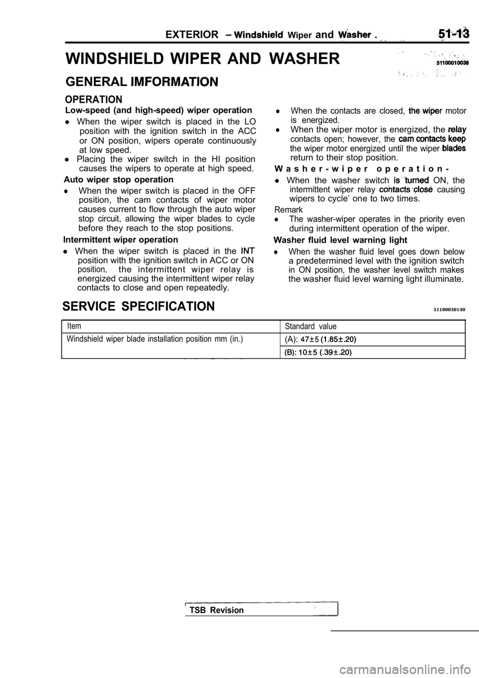
Windshield wiper blade installation position mm (in .)Standard value(A):
TSB Revision
Page 1947 of 2103
EXTERIOR Windshield Wiper and Washer,
CAUTION: SRSBefore removal of bag module and clockspring, refer to the follows:GROUP SRS Service Precautions.
GROUP Air Bag Module and ClockSpring.
Column switch removal steps
l Air bag module (Refer to GROUP Air Bag Module and Clock Spring.)l Steering wheel (Refer to GROUP Steering Wheel and Shaft.)
9. Column cover, lower
10. Column cover, upper
11. Column switch assembly
(with built-in wiper and washer
switch, and wiper relay)
12. Clock spring* (Refer to GROUP Air Bag Module and Clock
Spring.)
NOTE
Do not remove parts marked with* from the column sw itch
except when removal is absolutely necessary.
TSB Revision
Page 1948 of 2103
EXTERIOR Windshield Wiper and Washer
I
Inspection while operatingspeed speed
stop
INSTALLATION SERVICE POINT
WIPER ARM AND ASSEMBLY
INSTALLATION
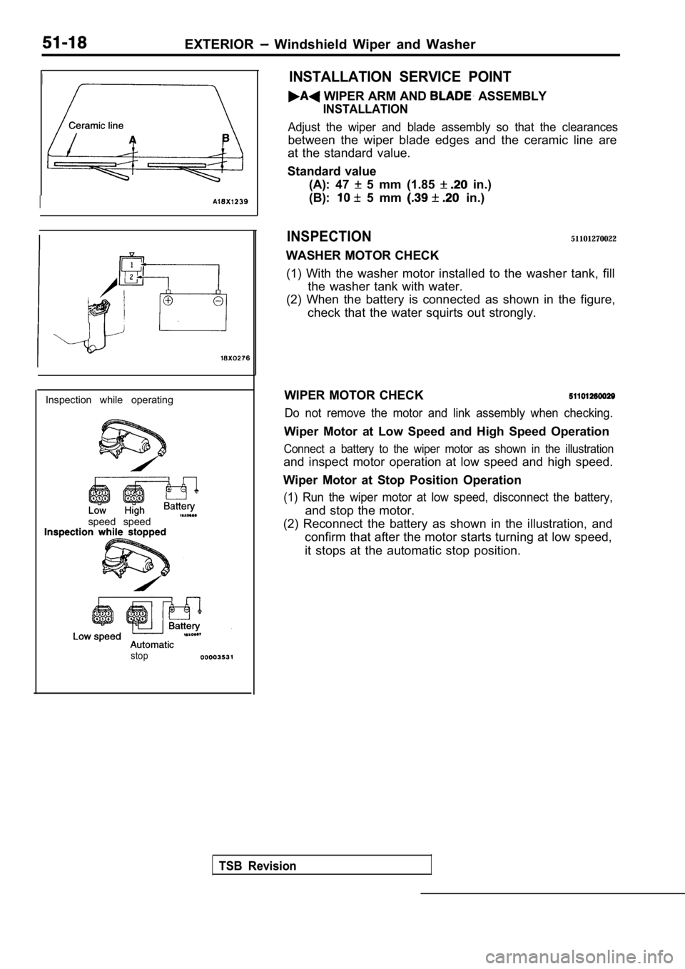
Adjust the wiper and blade assembly so that the cle arances
between the wiper blade edges and the ceramic line are
at the standard value.
Standard value (A): 47
5 mm (1.85 in.)
(B):
5 mm in.)
INSPECTION51101270022
WASHER MOTOR CHECK
(1) With the washer motor installed to the washer t ank, fill
the washer tank with water.
(2) When the battery is connected as shown in the f igure,
check that the water squirts out strongly.
WIPER MOTOR CHECK
Do not remove the motor and link assembly when chec king.
Wiper Motor at Low Speed and High Speed Operation
Connect a battery to the wiper motor as shown in the illustration
and inspect motor operation at low speed and high speed.
Wiper Motor at Stop Position Operation
(1) Run the wiper motor at low speed, disconnect th e battery,
and stop the motor.
(2) Reconnect the battery as shown in the illustrat ion, and
confirm that after the motor starts turning at low speed,
it stops at the automatic stop position.
TSB Revision
Page 1950 of 2103
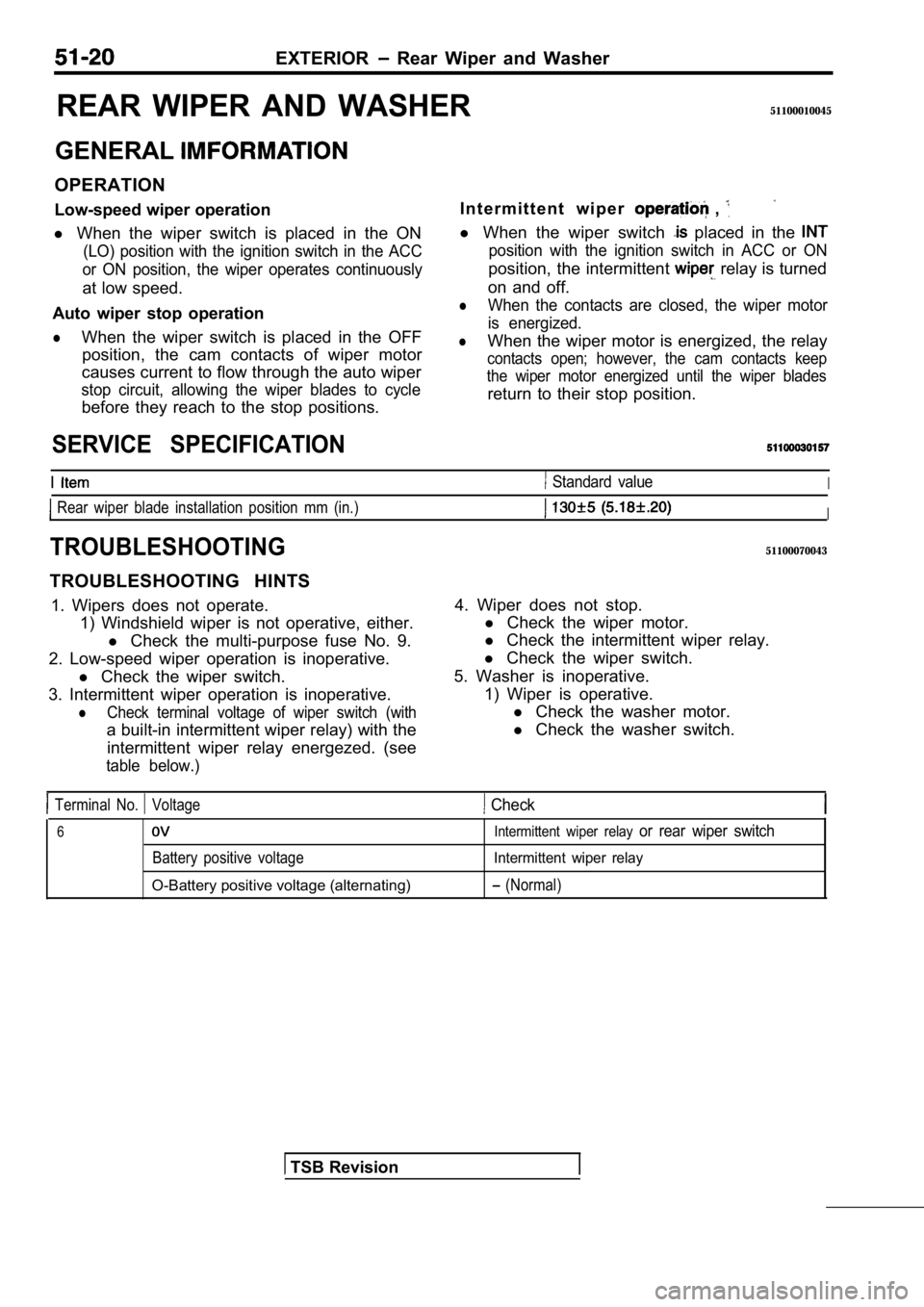
EXTERIOR Rear Wiper and Washer
REAR WIPER AND WASHER51100010045
GENERAL
OPERATION
Low-speed wiper operationI n t e r m i t t e n t w i p e r
,
l
When the wiper switch is placed in the ON
(LO) position with the ignition switch in the ACC
or ON position, the wiper operates continuously
at low speed.
Auto wiper stop operation
lWhen the wiper switch is placed in the OFF position, the cam contacts of wiper motor
causes current to flow through the auto wiper
stop circuit, allowing the wiper blades to cycle
before they reach to the stop positions. l
When the wiper switch
placed in the
position with the ignition switch in ACC or ON
position, the intermittent relay is turned
on and off.
lWhen the contacts are closed, the wiper motor
is energized.
lWhen the wiper motor is energized, the relay
contacts open; however, the cam contacts keep
the wiper motor energized until the wiper blades
return to their stop position.
SERVICE SPECIFICATION
I Standard valueI
Rear wiper blade installation position mm (in.)I
TROUBLESHOOTING51100070043
TROUBLESHOOTING HINTS
1. Wipers does not operate. 1) Windshield wiper is not operative, either.
l Check the multi-purpose fuse No. 9.
2. Low-speed wiper operation is inoperative. l Check the wiper switch.
3. Intermittent wiper operation is inoperative.
lCheck terminal voltage of wiper switch (with
a built-in intermittent wiper relay) with the intermittent wiper relay energezed. (see
table below.)
4. Wiper does not stop. l Check the wiper motor.
l Check the intermittent wiper relay.
l Check the wiper switch.
5. Washer is inoperative. 1) Wiper is operative.l Check the washer motor.
l Check the washer switch.
Terminal No. Voltage Check
6
Battery positive voltage
O-Battery positive voltage (alternating)
Intermittent wiper relay or rear wiper switch
Intermittent wiper relay
(Normal)
TSB Revision
Page 1953 of 2103
EXTERIOR Rear Wiper
INSTALLATION SERVICE POINT
ARM/WIPER BLADE INSTALLATION
Adjust the wiper arm so that the clearance the wiper
blade edge and the ceramic portion is at the
value.
Standard value (A): 130 mm (5.18 in.)
T S B R e v i s i o n