1990 MITSUBISHI SPYDER service
[x] Cancel search: servicePage 1997 of 2103
SUPPLEMENTAL,
SYSTEM
CONTENTS
AIR BAG MODULES DISPOSAL
PROCEDURES. . . . . . . . . . . . . . . . . . . . . . . . . . . .40
Deployed Air Bag Module Disposal . . . . . . . . . . .
44
Undeployed Air Bag Module Disposal . . . . . . . .40
AIR BAG MODULES AND CLOCK
SPRING. . . . . . . . . . . . . . . . . . . . . . . . . . . . . . . . .34
COMPONENT SERVICE
. . . . . . . . . . . . . . . . . . .31
GENERAL INFORMATION. . . . . . . . . . . . . . . . . .2
Circuit Diagram. . . . . . . . . . . . . . . . . . . . . . . . . . . . . .8
Componeni Location. . . . . . . . . . . . . . . . . . . . . . . .10
Configuration Diagrams. . . . . . . . . . . . . . . . . . . . . . .7
Construction Diagram. . . . . . . . . . . . . . . . . . . . . . . .3
Introduction. . . . . . . . . . . . . . . . . . . . . . . . . . . . . . . . . .2
Schematic. . . . . . . . . . . . . . . . . . . . . . . . . . . . . . . . . . .8
Warning/Caution Labels. . . . . . . . . . . . . . . . . . . . . . 4
MAINTENANCE. . . . . . . . . . . . . . . . . . . . . . . . . . .28
POST-COLLISION DIAGNOSIS
. . . . . . . . . . . .28
SPECIAL TOOLS. . . . . . . . . . . . . . . . . . . . . . . . . .13
SERVICE PRECAUTIONS. . . . . . . . . . . . . . . . . .11
SERVICE SPECIFICATIONS. . . . . . . . . .. . . .12
SRS AIR BAG UNIT (SRS-ECU)
. . . . . . . . . . . . . . . . . . . . . . . . . . . . . . . . . . . . . . . . . . .
32
TEST EQUIPMENT. . . . . . . . . . . . . . . . . . . . . . . .13
TROUBLESHOOTING. . . . . . . . . . . . . . . . . . . . .14
CAUTION
lCarefully read and observe the information in the S ERVICE PRECAUTIONS Prior to any service.lFor information troubleshooting or maintenance, always observe the procedures in the Troubleshooting or the respectively.
lIf any SRS components are removed or replaced in co nnection with any service procedures, be sure to follow the dures the COMPONENT SERVICE section for the components involved.lIf you have any questions about the please contact the Tech. Line.
Page 1998 of 2103
SRS General Information
GENERAL INFORMATION
INTRODUCTION
The Supplemental Restraint System (SRS) is
signed to supplement the driver’s and front passen-
ger’s seat belts to help reduce the risk or severity
of injury to the driver and front passenger by acti vat-
ing and deploying both air bags in certain frontal
collisions.
The SRS consists of: two air bag modules; one
located in the center of the steering wheel and
another one located above the glove box, which
contains. the folded air bag and an inflator unit;
the SRS air bag control unit (SRS-ECU) located
under the floor console assembly, which monitors
the system, and which contains a safing
sensor
and analog
sensor; an SRS warning light located
on the instrument panel, which indicates the
tional status of the SRS; spring-interconnec-
tion located within the the
It is not until the SRS-ECU in response to the outp ut
signal from the analog sensor, finds it necessary
to ignite the air bag, and the safing sensor is
caused to be ON that the SRS deploys the air
bag.
Only authorized service personnel should do work
on or around SRS components. Those service per-
sonnel should read this manual carefully before
starting any such work. Extreme care must be used
when servicing the SRS, to avoid
to the ser-
vice personnel (by inadvertent deployment of the
air bag) or to driver (by rendering the SRS inopera -
tive).
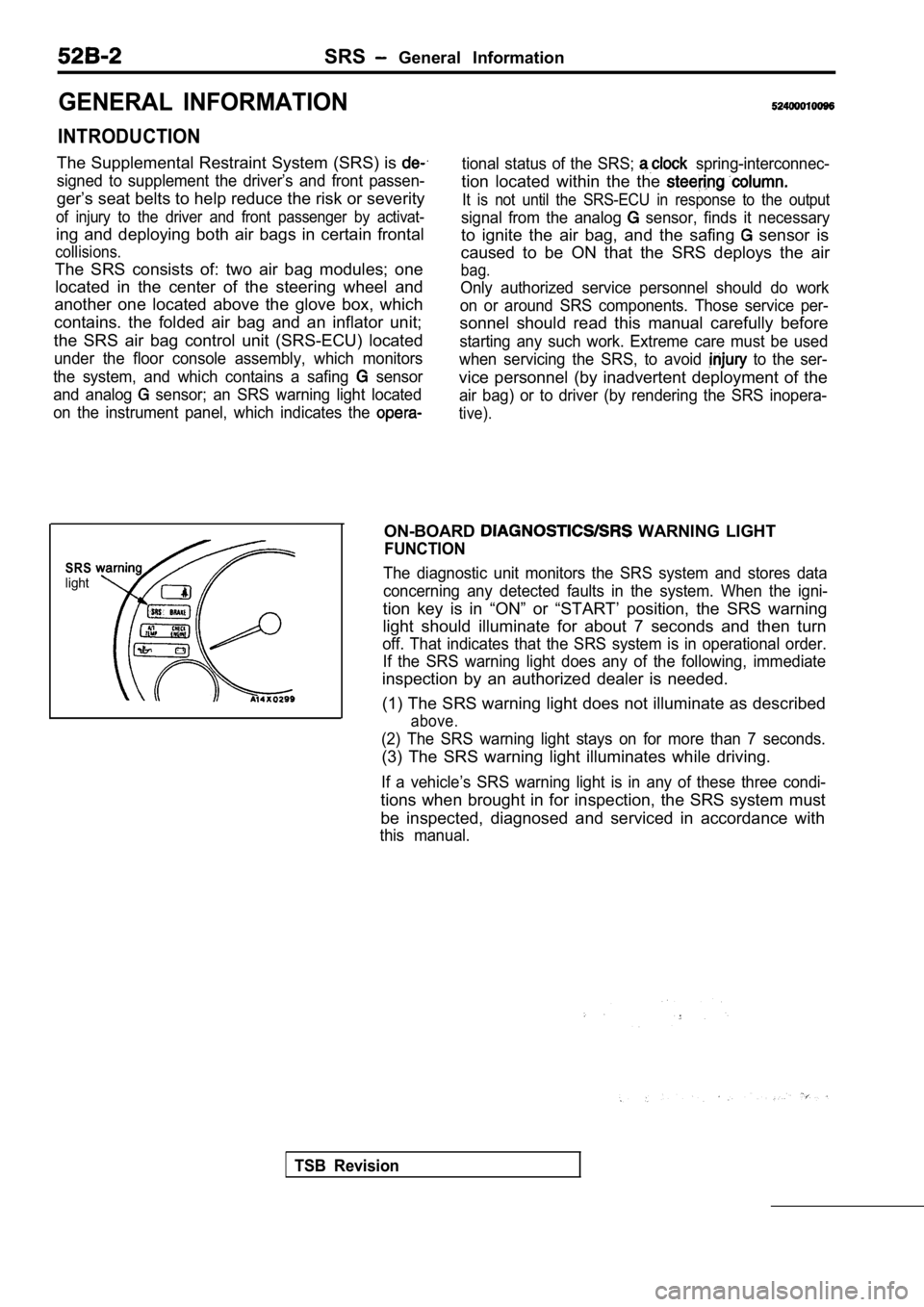
SRSlight
ON-BOARD WARNING LIGHT
FUNCTION
The diagnostic unit monitors the SRS system and sto res data
concerning any detected faults in the system. When the igni-
tion key is in “ON” or “START’ position, the SRS wa rning
light should illuminate for about 7 seconds and the n turn
off. That indicates that the SRS system is in operational order.
If the SRS warning light does any of the following, immediate
inspection by an authorized dealer is needed.
(1) The SRS warning light does not illuminate as de scribed
above.
(2) The SRS warning light stays on for more than 7 seconds.
(3) The SRS warning light illuminates while driving.
If a vehicle’s SRS warning light is in any of these three condi-
tions when brought in for inspection, the SRS syste m must
be inspected, diagnosed and serviced in accordance with
this manual.
TSB Revision
Page 2001 of 2103
SRS General- Jnformation
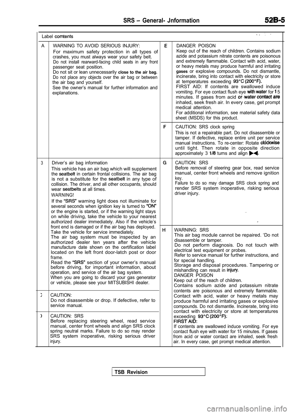
Label
A WARNING TO AVOID SERIOUS INJURY:DANGER POISON
For maximum safety protection in all types ofKeep out of the reach of children. Contains sodium
crashes, you must always wear your safety belt. azide and potassium nitrate contents are poisonous
Do not install rearward-facing child seats in any f
rontand extremely flammable. Contact with acid, water,
passenger seat position. or heavy metals may produce harmful and irritating
Do not sit or lean unnecessarily
close to the air bag. gasesor explosive compounds. Do not dismantle,
Do not place any objects over the air bag or betwee
nincinerate, bring into contact with electricity or store
the air bag and yourself. at temperatures exceeding
See the owner’s manual for further information andFIRST AID: If contents are swallowed induce
explanations.vomiting. For eye contact flush eye for 5
minutes. If gases from acid
inhaled, seek fresh air. In every case, get prompt
medical attention.
For additional information, see material safety dat a
sheet (MSDS) for this product.
CAUTION: SRS clock spring
This is not a repairable part. Do not disassemble o r
tamper. If defective, replace entire unit per servi ce
manual instructions. To re-center: Rotate
until tight. Then rotate in opposite direction
approximately 3 turns and align
3Driver’s air bag informationCAUTION: SRS
This vehicle has an air bag which will supplementBefore removal of steering gear box, read service
the
in certain frontal collisions. The air bagmanual, center front wheels and remove ignition
is not a substitute for the
in any type ofkey.
collision. The driver, and all other occupants, sho uldFailure to do so may damage SRS clock spring and
wear at all times.render SRS system inoperative, risking serious
WARNING!driver injury.
If the warning light does not illuminate for
several seconds when ignition key is turned to
or the engine is started, or if the warning light stays
on while driving, take the vehicle to your nearest
authorized dealer immediately. Also if the vehicle’ s
front end is damaged or if the air bag has deployed .
Take the vehicle for service immediately.WARNING: SRS
The air bag system must be inspected by an This air bag module cannot be repaired. ‘Do not
authorized dealer ten years after the vehicledisassemble or tamper.
manufacture date shown on the certification labelDo not perform diagnosis. Do not touch with
located on the left front door-latch post or door
electrical test equipment or probes.
frame.Refer to service manual for further instructions, a nd
Read the section of your owner’s manualfor special handling.
before driving, for important information, about Storage and disposal procedures. Tampering or
operation, and service of the air bag system. mishandling can result in
When you are going to discard your gas generatorDANGER POISON
or vehicle, please see your MITSUBISHI dealer. Keep out of the reach of children.
Contains sodium azide and potassium nitrate
CAUTION:contents are poisonous and extremely flammable.
Do not disassemble or drop. If defective, refer toContact with acid, water or heavy metals may
service manual.produce harmful and irritating gases or explosive
compounds. Do not dismantle. Incinerate, bring into
CAUTION: SRScontact with electricity or store at temperatures
exceeding
Before replacing steering wheel, read service
manual, center front wheels and align SRS clockIf contents are swallowed induce vomiting. For eye
spring neutral marks. Failure to do so may render contact flush eye with water for 15 minutes. If gases
SRS system inoperative, risking serious driverfrom acid or water contact are inhaled, seek freshinjury.air. In every case, get prompt medical attention.
TSB Revision
Page 2007 of 2103
SRS Service Precautions
SERVICE PRECAUTIONS52400020092
1. In order to avoid injury to yourself or others
from accidental deployment of the air bag during
servicing, read and carefully follow all the
cautions and procedures described in this
manual.
2. Do not use any electrical test equipment on
or near SRS components, except those
fiedon and
Never use an analog ohmmeter.
3.Never Attempt to Repair the Following
ponents:
SRS Air Bag Control Unit (SRS-ECU)
Clock Spring
Air Bag Module If any of these components are diagnosed as
faulty, they should only be replaced, in
dance with the COMPONENT SERVICE
dures in this manual, starting at page
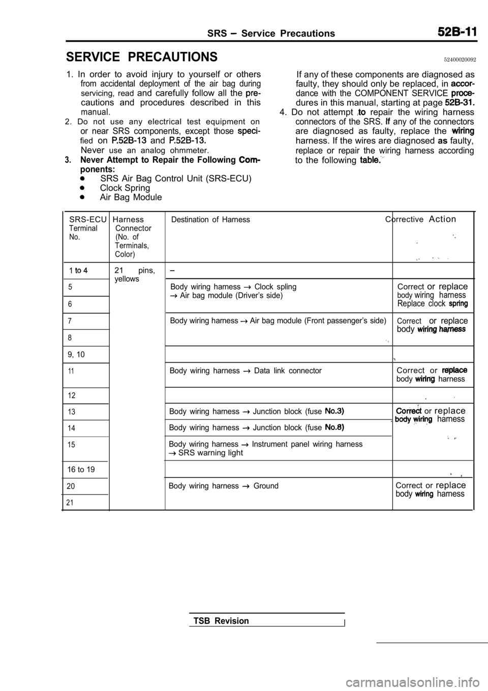
4. Do not attempt repair the wiring harness
connectors of the SRS. any of the connectors
are diagnosed as faulty, replace the
harness. If the wires are diagnosed asfaulty,
replace or repair the wiring harness according
to the following
SRS-ECU HarnessDestination of HarnessCorrective A c t i o n
TerminalConnector
No.(No. of
Terminals,
Color)
121 pins,
yellows5Body wiring harness Clock splingCorrector replace
Air bag module (Driver’s side)bodywiring harness
6Replace clock
7Body wiring harness Air bag module (Front passenger’s side)Corrector replace
body
8
9, 10
11Body wiring harness Data link connectorCorrect or
body harness
12
13
14
15
Body wiring harness Junction block (fuse
Body wiring harness Junction block (fuse
Body wiring harness Instrument panel wiring harness
SRS warning light .
or
replace. harness
16 to 19 ,
20
21
Body wiring harness GroundCorrect or replace
body harness
TSB RevisionI
Page 2008 of 2103
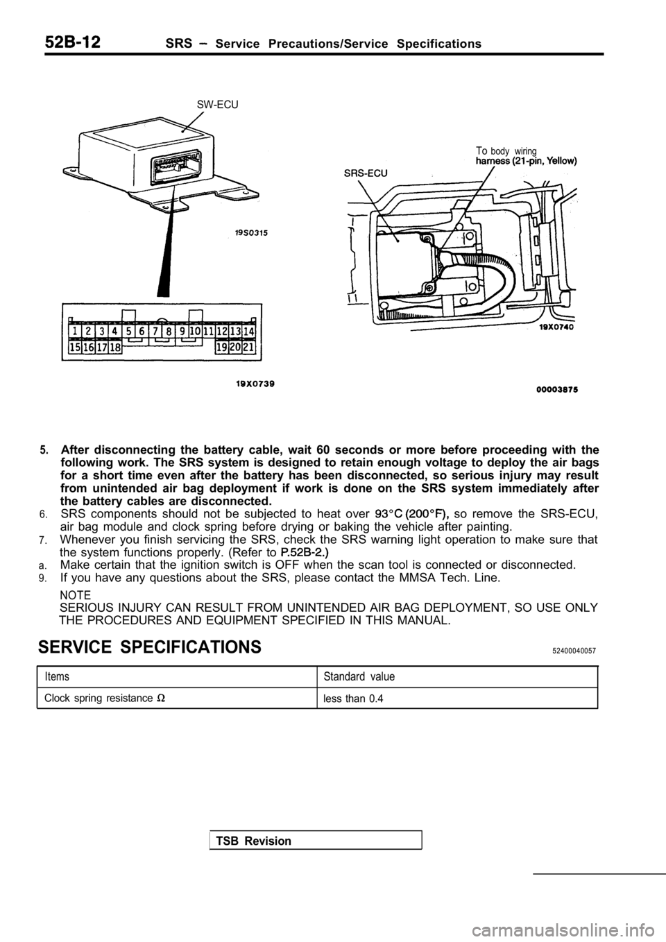
SRS Service Precautions/Service Specifications
5.
6.
7.
a.
9.
SW-ECU
Tobody wiring
After disconnecting the battery cable, wait 60 seco nds or more before proceeding with the
following work. The SRS system is designed to retai n enough voltage to deploy the air bags
for a short time even after the battery has been di sconnected, so serious injury may result
from unintended air bag deployment if work is done on the SRS system immediately after
the battery cables are disconnected. SRS components should not be subjected to heat over
so remove the SRS-ECU,
air bag module and clock spring before drying or ba king the vehicle after painting.
Whenever you finish servicing the SRS, check the SR S warning light operation to make sure that
the system functions properly. (Refer to
Make certain that the ignition switch is OFF when t he scan tool is connected or disconnected.
If you have any questions about the SRS, please con tact the MMSA Tech. Line.
NOTE
SERIOUS INJURY CAN RESULT FROM UNINTENDED AIR BAG D EPLOYMENT, SO USE ONLY
THE PROCEDURES AND EQUIPMENT SPECIFIED IN THIS MANU AL.
SERVICE SPECIFICATIONS52400040057
ItemsStandard value
Clock spring resistance less than 0.4
TSB Revision
Page 2024 of 2103
SRS Troubleshooting/Maintenance/Post-collision Diagnosis
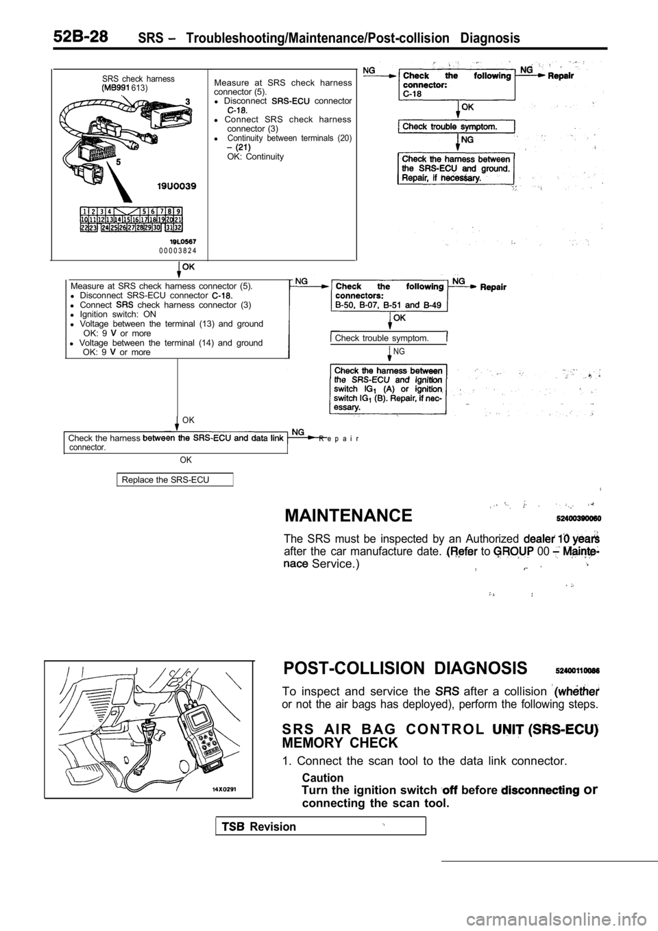
SRS check harness 613).
0 0 0 0 3 8 2 4Measure at SRS check harness
connector (5). l Disconnect
connector
l Connect SRS check harness
connector (3)
l
Continuity between terminals (20)
OK: Continuity
Measure at SRS check harness connector (5).
l Disconnect SRS-ECU connector
l Connect check harness connector (3)
l Ignition switch: ON
l Voltage between the terminal (13) and ground
OK: 9
or more
l Voltage between the terminal (14) and ground
OK: 9
or more
Check trouble symptom.
NG
OK
Check the harness R e p a i r connector.
OK
Replace the SRS-ECU
MAINTENANCE
,
The SRS must be inspected by an Authorized
after the car manufacture date. to 00
Service.)
POST-COLLISION DIAGNOSIS
To inspect and service the after a collision
or not the air bags has deployed), perform the foll owing steps.
S R S A I R B A G C O N T R O L
MEMORY CHECK
1. Connect the scan tool to the data link connector .
Caution
Turn the ignition switch before or
connecting the scan tool.
Revision
Page 2025 of 2103
SRS Post-collision Diagnosis
2. Read (and write down) all displayed diagnostic trouble
codes. (Refer to
NOTE
If the battery power supply has’ been disconnected or
disrupted by the collision, the scan tool cannot communi-
cate with the SRS-ECU.
and, ‘if necessary, repair
the body wiring harness before proceeding further.
3.Read the service data (fault duration and times
the memory was erased) using the Scan
NOTE
lMaximum stored period: 9999 minutes (approximately
7 days)
lMaximum number of times to be 250
4.Erase the diagnostic trouble codes, then wait 5 sec onds
or more, read and write down all displayed diagnost ic
trouble codes. (Refer to
REPAIR PROCEDURE
WHEN AIR BAG DEPLOYS IN A COLLISION.
1. Replace the following parts with new ones. l SRS air bag control unit (SRS-ECU) (Refer
l Air bag modules (Refer to
2.Check the following parts, and replace if any malfu nctions
are present.
l Clock spring (Refer to
l Steering wheel, steering column and intermediate
joint
(1) Check wiring harness (built, into’ steering whe el)
and connectors for damage, and terminals for
deformation.
(2) install air bag module to check fit or alignment
with steering wheel,.
(3) Check steering wheel for noise, binds or difficult
operation and excessive free play.
3. Check harnesses for binding, connectors for dama ge,
poor connections, and terminals for deformation.
(Refer to
WHEN AIR BAG DOES NOT IN LOW-SPEED
COLLISION.
Check the SRS components.
If the SRS components are showing any visible damag e such
as dents, cracks, or deformation, replace them with new ones.
Concerning parts removed for inspection, replacemen t
new parts and cautionary points for working, to
appropriate COMPONENT SERVICE,
TSB Revision
Page 2026 of 2103
SRS Post-collision Diagnosis/Component Service
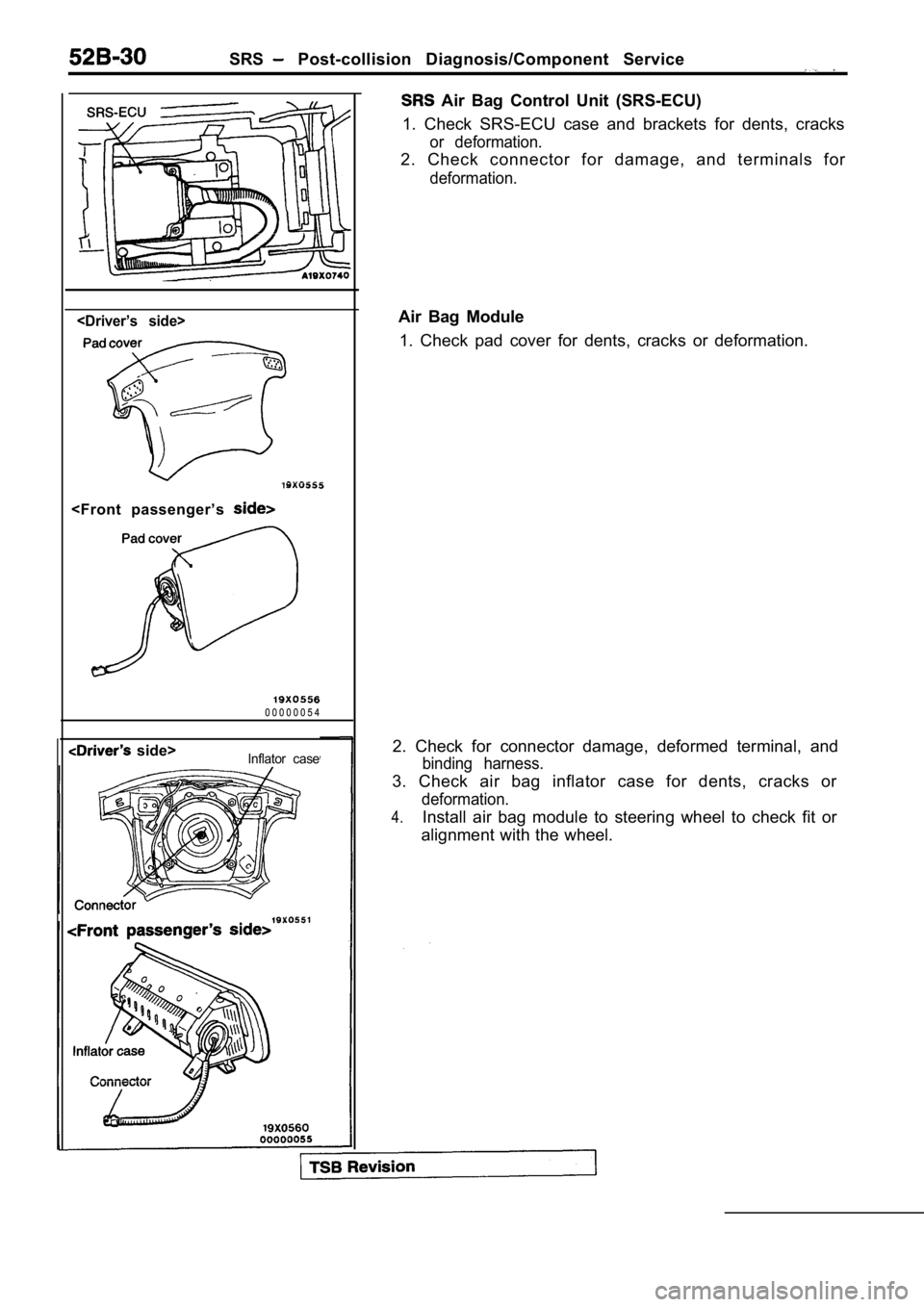
Air Bag Control Unit (SRS-ECU)
1. Check SRS-ECU case and brackets for dents, crack s
or deformation.
2. Check connector for damage, and terminals for
deformation.
side>Inflator case
Air Bag Module
1. Check pad cover for dents, cracks or deformation .
2. Check for connector damage, deformed terminal, a nd
binding harness.
3. Check air bag inflator case for dents, cracks or
deformation.
4.Install air bag module to steering wheel to check fit or
alignment with the wheel.