Page 1956 of 2103
51-26EXTERIOR Door Mirror
section
1 2 3
4 5 6 7
REMOVAL SERVICE POINT
MIRROR REMOVAL
Turn the mirror by hand so that it faces upwards, the
flat-tipped screwdriver wound with masking tape int o the
notched section, and lever out. the mirror to remov e it.
INSPECTION
ELECTRICALLY CONTROLLED
Check that the mirror moves as described the
each terminal is connected to the
Battery connection terminal
1 6
Direction of operation
I UP
DOWN
LEFT
I RIGHT
DOOR MIRROR CONTROL SWITCH CONTINUITY CHECK
51100710020
RIGHTLeft side
Right side
0
TSB Revision
Page 1959 of 2103

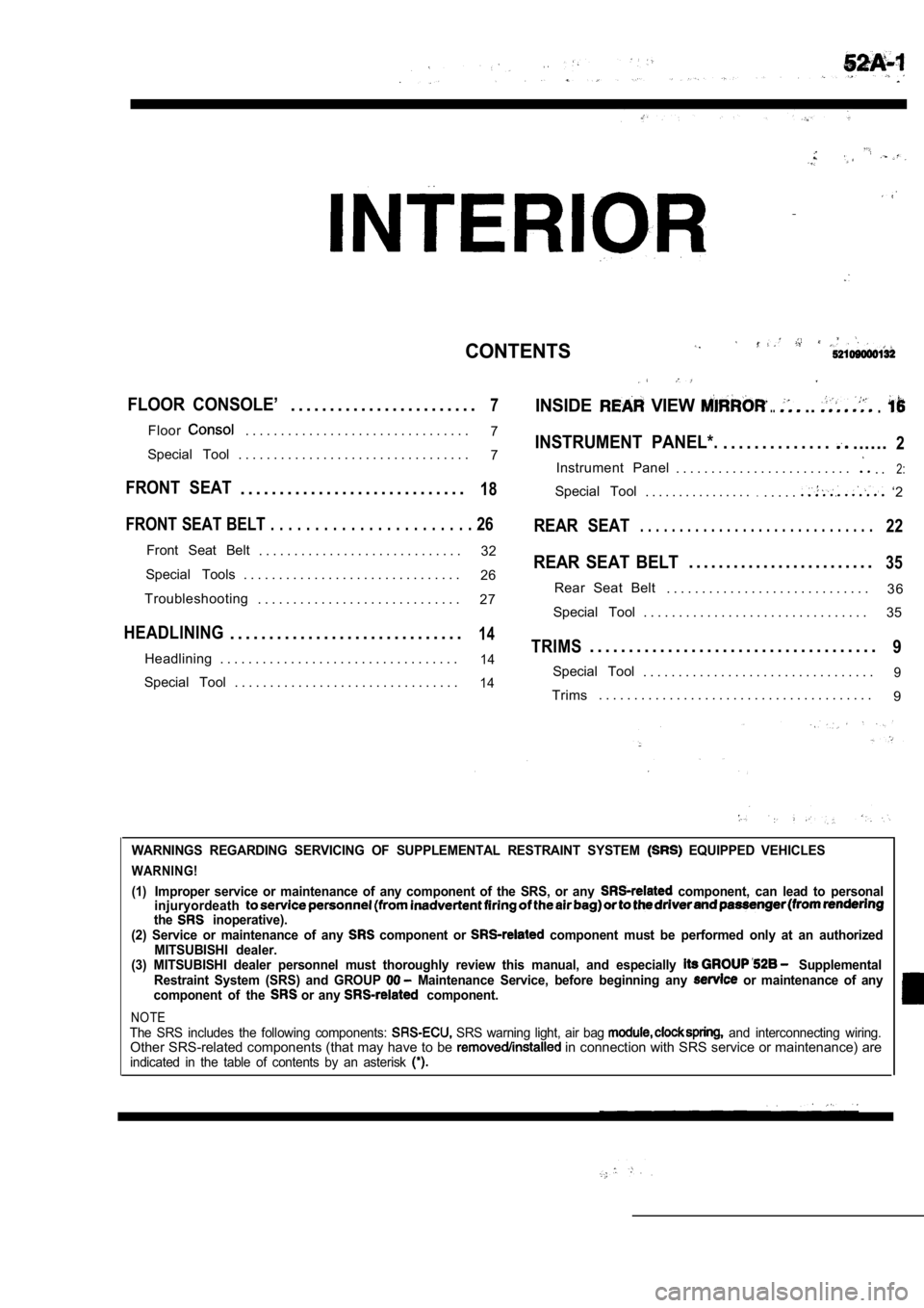
CONTENTS
FLOOR CONSOLE’. . . . . . . . . . . . . . . . . . . . . . . .7INSIDE VIEW .....
Floor. . . . . . . . . . . . . . . . . . . . . . . . . . . . . . . .7INSTRUMENT PANEL*.. . . . . . . . . . . . . .......2Special Tool . . . . . . . . . . . . . . . . . . . . . . . . . . . . . . . . . 7
Instrument Panel . . . . . . . . . . . . . . . . . . . . . . . . .. .2:
FRONT SEAT. . . . . . . . . . . . . . . . . . . . . . . . . . . . .18Special Tool. . . . . . . . . . . . . . . ... . . . .. ‘2
FRONT SEAT BELT . . . . . . . . . . . . . . . . . . . . . . . 26REAR SEAT. . . . . . . . . . . . . . . . . . . . . . . . . . . . . .22
Front Seat Belt
. . . . . . . . . . . . . . . . . . . . . . . . . . . . . 32REAR SEAT BELT. . . . . . . . . . . . . . . . . . . . . . . . .35Special Tools . . . . . . . . . . . . . . . . . . . . . . . . . . . . . . .
26
3 6
Troubleshooting Rear Seat Belt
. . . . . . . . . . . . . . . . . . . . . . . . . . . . .
. . . . . . . . . . . . . . . . . . . . . . . . . . . . . 27
Special Tool . . . . . . . . . . . . . . . . . . . . . . . . . . . . . . . . 35
HEADLINING. . . . . . . . . . . . . . . . . . . . . . . . . . . . . .14TRIMS. . . . . . . . . . . . . . . . . . . . . . . . . . . . . . . . . . . . .9Headlining . . . . . . . . . . . . . . . . . . . . . . . . . . . . . . . . . .14Special Tool. . . . . . . . . . . . . . . . . . . . . . . . . . . . . . . . .9Special Tool . . . . . . . . . . . . . . . . . . . . . . . . . . . . . . . .14Trims. . . . . . . . . . . . . . . . . . . . . . . . . . . . . . . . . . . . . . .
9
WARNINGS REGARDING SERVICING OF SUPPLEMENTAL RESTRA INT SYSTEM EQUIPPED VEHICLES
WARNING!
(1)
Improper service or maintenance of any component of the SRS, or any component, can lead to personal
injuryordeath
the inoperative).
(2) Service or maintenance of any component or component must be performed only at an authorized
MITSUBISHI dealer.
(3) MITSUBISHI dealer personnel must thoroughly rev iew this manual, and especially
Supplemental
Restraint System (SRS) and GROUP Maintenance Service, before beginning any or maintenance of any
component of the or any component.
NOTEThe SRS includes the following components: SRS warning light, air bag and interconnecting wiring.Other SRS-related components (that may have to be in connection with SRS service or maintenance) areindicated in the table of contents by an asterisk
Page 1960 of 2103
INTERIOR Instrument Panel
INSTRUMENT PANEL
.
52100050055
SPECIAL TOOL
ToolTool number and name
General Service tool
Ornament remover
Application
Removal of switch, trim, etc.
INSTRUMENT PANEL52100170154
For installation of the instrument panel, the bolts
and screws described below are used. They are indicated by symbols in the illustration.
Thread diameter
Effective thread length
TSB Revision
Page 1962 of 2103

INTERIOR Instrument Panel
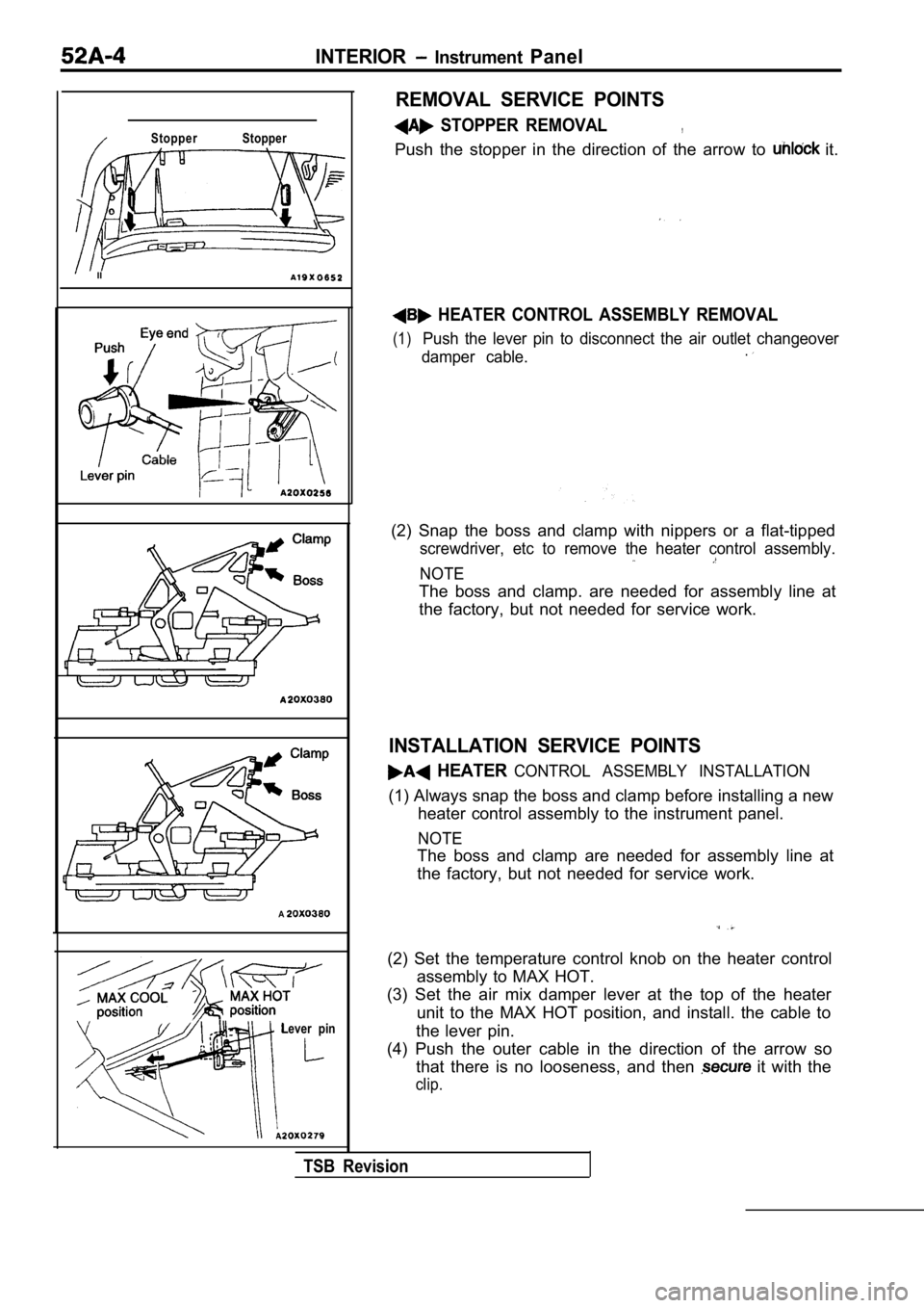
Stopper Stopper
II
A
Lever pin
REMOVAL SERVICE POINTS
STOPPER REMOVAL,
Push the stopper in the direction of the arrow to it.
HEATER CONTROL ASSEMBLY REMOVAL
(1)Push the lever pin to disconnect the air outlet changeover
damper cable..
(2) Snap the boss and clamp with nippers or a flat- tipped
screwdriver, etc to remove the heater control assem bly.
NOTE
The boss and clamp. are needed for assembly line at
the factory, but not needed for service work.
INSTALLATION SERVICE POINTS
HEATER CONTROL ASSEMBLY INSTALLATION
(1) Always snap the boss and clamp before installing a new
heater control assembly to the instrument panel.
NOTE
The boss and clamp are needed for assembly line at
the factory, but not needed for service work.
(2) Set the temperature control knob on the heater control
assembly to MAX HOT.
(3) Set the air mix damper lever at the top of the heater
unit to the MAX HOT position, and install. the cabl e to
the lever pin.
(4) Push the outer cable in the direction of the ar row so
that there is no looseness, and then
it with the
clip.
TSB Revision
Page 1965 of 2103
INTERIOR Floor Console
FLOOR CONSOLE
SPECIAL TOOL
ToolTool number and nameSupersession Application
General service tool Removal of panel, holder, etc.
FLOOR CONSOLE
REMOVAL AND INSTALLATION
CAUTION:When removing and installing the floor console as-sembly, do not let it bump against the
NOTE Metal clip position
Removal steps
1. Center console panel
2. Ashtray and cupholder assembly
3. Ashtray
4. Cup holder 5. Shift lever knob
6. Floor console assembly
7. Ashtray illumination light bracket
TSB Revision
Page 1967 of 2103
INTERIOR Trims
TRIMS
SPECIAL TOOL
ToolTool number and nameA p p l i c a t i o n
General service tool Removal of trims,
TRIMS
REMOVAL AND INSTALLATION
Metal clip position
Resin clip position
00003812
B - B
Cliplip
II
Cowl side trim removal steps 1. Scuff plate
2. Cowl side trim
Front pillar trim removal steps 3. Assist grip
4. Front pillar trim c - c
Clip
Quarter
trim, upper
Quarter trim removal steps
l Rear seat cushion (Refer to
l Front seat belt anchor plate
(Refer to
l Rear seat belt anchor plate
Coat bracket
7. Quarter trim, upper
TSBRevision
Page 1971 of 2103
lower
Belt guide
cover
REMOVAL SERVICE POINT ,
END TRIM REMOVAL
(1) Remove the four lower clips of end
(2) Remove the six upper clips of the rear end trim , and
then pull up the trim.
INSTALLATION SERVICE POINT
OUTER SEAT BELT ANCHOR PLATE
INSTALLATION
Install the anchor along bead of the
BELT GUIDE COVER INSTALLATION
Accurately insert the belt guide 5 claws into the h oles on
quarter trim, lower.
TSB Revision
Page 1972 of 2103
HEADLINING
INTERIOR Headlining
SPECIAL TOOL
ToolTool number and name
General service toolApplication
Removal of trims, etc.
HEADLINING
REMOVAL AND INSTALLATION
52100140178
and Post-installation Operationl Front Pillar Trim and Quarter Trim Upper Removaland Installation (Refer to
NOTE Metal clip position
Removal steps
a s s e m b l y
2. holder
3. Dome light assembly
4. Rear roof rail trim
5. Headlining
TSB Revision
Rear roof rail trimI