1990 MITSUBISHI SPYDER sensor
[x] Cancel search: sensorPage 750 of 2103

ENGINE AND EMISSION CONTROL Auto-cruise
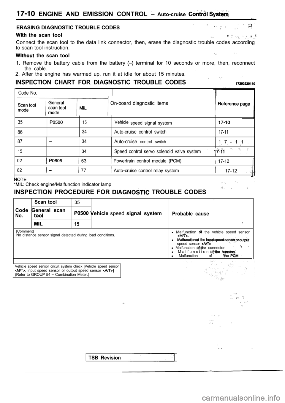
ERASING DIAGNOSTIC TROUBLE CODES .
the scan tool
Connect the scan tool to the data link connector, then, erase the diagnostic trouble codes according
to scan tool instruction.
the scan tool
1. Remove the battery cable from the battery terminal for 10 seconds or more, then, reconnect
the cable.
2. After the engine has warmed up, run it at idle f or about 15 minutes.
INSPECTION CHART FOR DIAGNOSTIC TROUBLE CODES
Code No.
On-board diagnostic items
35
86
15
34
Vehiclespeed signal system
Auto-cruise control switch17-11
87
15
34
34
Auto-cruisecontrol switch1 7 - 1 1
Speed control servo solenoid valve system
02 53 Powertrain control module (PCM)I17-12
82
77Auto cruise control relay system 17-12
Check engine/Malfunction indicator lamp
INSPECTION PROCEDURE FOR TROUBLE CODES
Scan tool35
Code General scan
No. Vehicle speedsignal systemProbable cause
15.
[Comment]No distance sensor signal detected during load cond itions.l
Malfunction the vehicle speed sensor
l the speed sensor l Malfunction connector.l M a l f u n c t i o nl Malfunction of . .
Vehicle speed sensor circuit system check [Vehicle speed sensor input speed sensor or output speed sensor (Refer to GROUP 54 Combination Meter.)
TSB Revision
Page 755 of 2103
![MITSUBISHI SPYDER 1990 Service Repair Manual ENGINE AND EMISSION CONTROL Auto-cruise System
INSPECTION PROCEDURE 6
Auto-cruise control cannot be set.
[Comment]A malfunction of the auto-cruise control switch circuit may exist. MITSUBISHI SPYDER 1990 Service Repair Manual ENGINE AND EMISSION CONTROL Auto-cruise System
INSPECTION PROCEDURE 6
Auto-cruise control cannot be set.
[Comment]A malfunction of the auto-cruise control switch circuit may exist.](/manual-img/19/57345/w960_57345-754.png)
ENGINE AND EMISSION CONTROL Auto-cruise System
INSPECTION PROCEDURE 6
Auto-cruise control cannot be set.
[Comment]A malfunction of the auto-cruise control switch circuit may exist.
c a u s e,lMalfunction of the auto-cruise control switch
l M a l f u n c t i o n o f spring.
l Malfunction of the connector.
l
of
Auto-cruise control switch checkN G
Measure at clock spring connector
Disconnect the connector and mea-
* Voltage between terminal (3) and
and 40 Check trouble symptom.
Check the harness between the clockspring and ground. Repair, if necessary.
INSPECTION PROCEDURE 7
Hunting (repeated acceleration and deceleration) oc curs at the
set vehicle speed.
[Comment]
A malfunction of a speed sensor, the speed control servo, or the vacuum supply may be present.
For vehicle speed sensor checkFor input speed sensor or output speed sensor check(Refer to GROUP 54 Combination Meter.)
Speed control servo checkN G
Probable cause
lMalfunction the vehicle speed sensor lMalfunction of the input speed or outputspeed sensor l Malfunction of the l Malfunction of the vacuum supply.
l Malfunction of the PCM.
OK
Vacuum supply check (ReferNG
the PCM.
INSPECTION PROCEDURE 8
When the auto-cruise control main switch is ON, the switch
indicator on the instrument panel does not illumina te.
(However, auto-cruise control is normal.) Probable cause
[Comment]l
Malfunction of the auto-cruise control main
Blown bulb in auto-cruise control main switch.switch.
theau t o - c r u i s e c o n t r o l m a i n s w i t c h .
TSB Revision
Page 759 of 2103

AND CONTROL
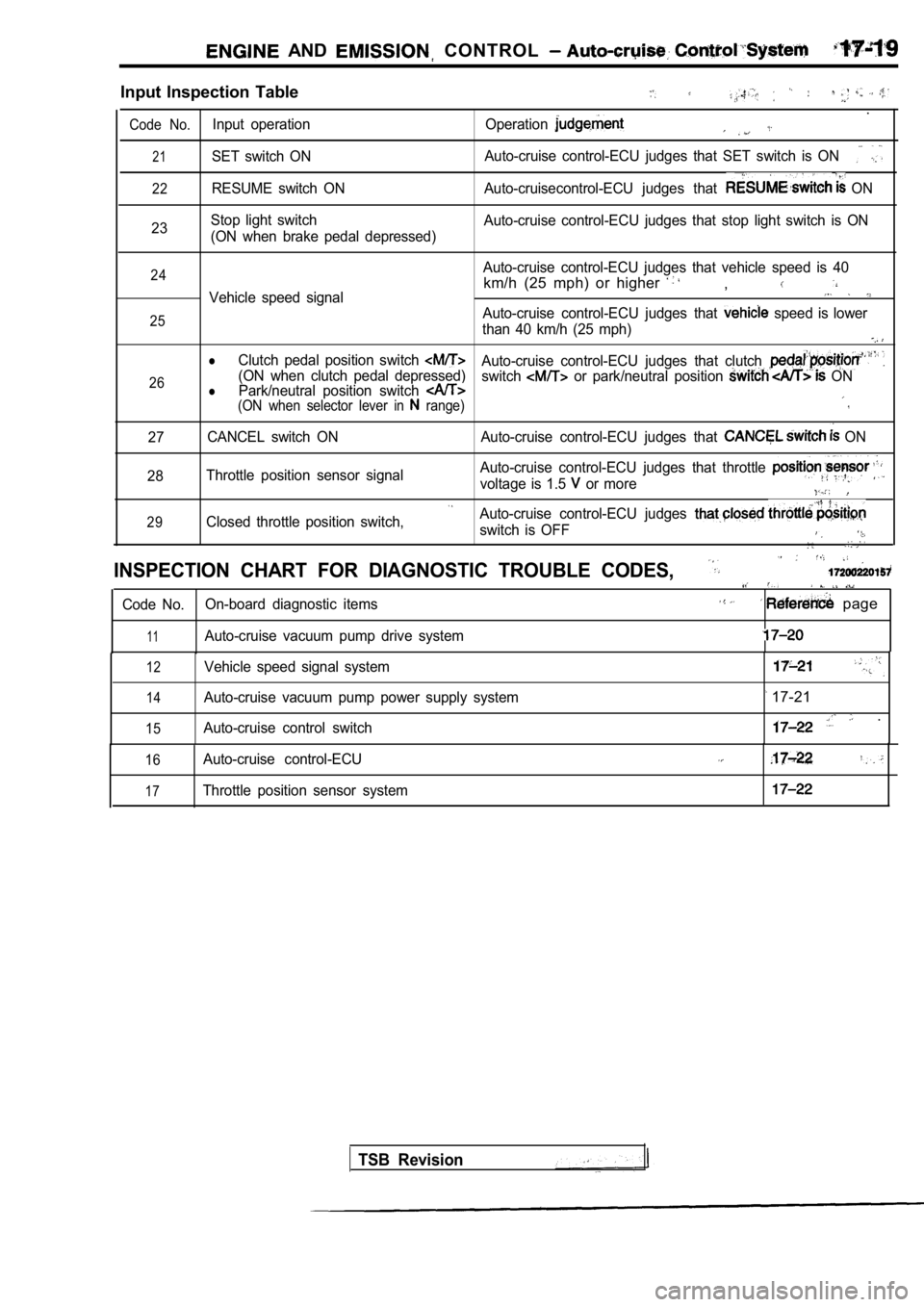
Input Inspection Table
.
Code No.Input operation Operation
21SET switch ONAuto-cruise control-ECU judges that SET switch is O
N
22RESUME switch ON Auto-cruisecontrol-ECU judges that ON
23 Stop light switch
(ON when brake pedal depressed) Auto-cruise control-ECU judges that stop light swit
ch is ON
24
25
26Auto-cruise control-ECU judges that vehicle speed i s 40
km/h (25 mph) or higher ,Vehicle speed signal
Auto-cruise control-ECU judges that speed is lower
than 40 km/h (25 mph)
lClutch pedal position switch Auto-cruise control-ECU judges that clutch (ON when clutch pedal depressed) Park/neutral position switch switch or park/neutral position ONl(ON when selector lever in range)
27 CANCEL switch ON Auto-cruise control-ECU judges that
ON
28 Throttle position sensor signal Auto-cruise control-ECU judges that throttle
voltage is 1.5 or more
29Closed throttle position switch,Auto-cruise control-ECU judges
switch is OFF
INSPECTION CHART FOR DIAGNOSTIC TROUBLE CODES,
Code No.
On-board diagnostic items page
11Auto-cruise vacuum pump drive system
12
14
15
Vehicle speed signal system
Auto-cruise vacuum pump power supply system
Auto-cruise control switch
17-21
.
16
17
Auto-cruise control-ECU
Throttle position sensor system
TSB Revision
Page 761 of 2103
![MITSUBISHI SPYDER 1990 Service Repair Manual ENGINE AND EMISSION CONTROL Auto-cruise Control’
Code 2 Vehicle speed signal system
[Comment]l Malfunction of the vehicle This diagnostic trouble code is output if the vehic le speed signa MITSUBISHI SPYDER 1990 Service Repair Manual ENGINE AND EMISSION CONTROL Auto-cruise Control’
Code 2 Vehicle speed signal system
[Comment]l Malfunction of the vehicle This diagnostic trouble code is output if the vehic le speed signa](/manual-img/19/57345/w960_57345-760.png)
ENGINE AND EMISSION CONTROL Auto-cruise Control’
Code 2 Vehicle speed signal system
[Comment]l Malfunction of the vehicle This diagnostic trouble code is output if the vehic le speed signals from the vehicle speed sensor l of connectorare not input to the auto-cruise control-ECU when t he vehicle speed is 40 km/h (25 mph) l
Malfunction of the harness
or more. l Malfunction of the auto-cruise
Check the vehicle speed sen(Refer to GROUP 54 CombinationMeter.)
1. NG
Measure at the vehicle speed sensor connector Check the following connector. l Disconnect the connector, and measure at the
harness side.O K
1. Voltage between 1 and ground (Ignition switch: ON)
NG
System voltage
2.Voltage between 3 and ground2. N G(Ignition switch: ON)
OK: 4.6 5.2 3.Continuity between 2 and ground3. N G
OK: Continuity
OK
Check trouble symptom.
N G
Check the harness between the speed sensor
Check the following
OKNG
Check trouble symptom.
NG
Check the harness between the auto-cruise ECU and the vehicle soeed sensor connector.
OKNG
Replace the auto-cruise control-ECU.
and ignition switch connector
OK
Check the ignition switch.
(Refer to GROUP 54 , ,
Check the harness between the vehicle speed sensorand the ground. Repair, if necessary.
Code Autocruise vacuum pump power supply systemProbable cause
[Comment]
This code will be output when the drive signals for the auto-cruise vacuum pump release valve,
control valve and motor are not input to the auto-c ruise control-ECU.l
the stop light l
Malfunction of the connector
l
l of the auto-cruise
at the auto-cruise vacuum
l Disconnect the connector and
l Voltage between terminal (1) and
OKN G Check the harness between the cruise vacuum pump and the cruise control-ECU.
and
Replace the auto-cruise control-ECU.
TSB Revision
Page 762 of 2103

17-22ENGINE AND EMISSION CONTROL Auto-cruise Control System
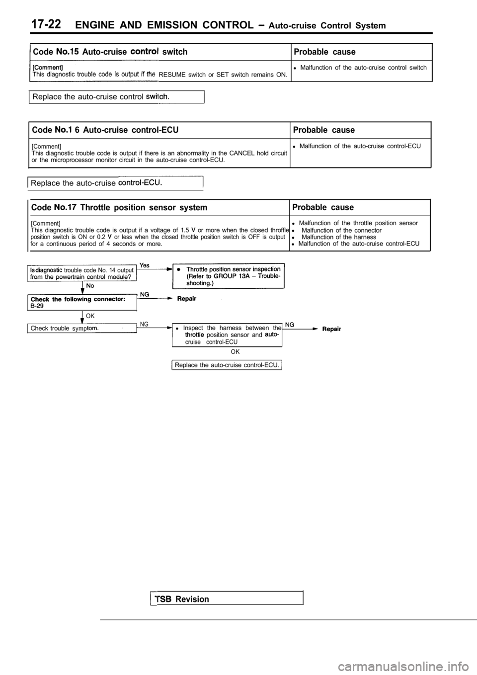
Code Auto-cruise switch Probable cause
l Malfunction of the auto-cruise control switch
This diagnostic trouble code is output if the RESUME switch or SET switch remains ON.
Replace the auto-cruise control
Code 6 Auto-cruise control-ECU Probable cause
[Comment]l Malfunction of the auto-cruise control-ECU
This diagnostic trouble code is output if there is an abnormality in the CANCEL hold circuit
or the microprocessor monitor circuit in the auto-c ruise control-ECU.
Replace the auto-cruise
Code Throttle position sensor system Probable cause
[Comment]l
Malfunction of the throttle position sensor
This diagnostic trouble code is output if a voltage of 1.5 or more when the closed throffle l
Malfunction of the connectorposition switch is ON or 0.2 or less when the closed throttle position switch i s OFF is outputlMalfunction of the harness
for a continuous period of 4 seconds or more. l
Malfunction of the auto-cruise control-ECU
trouble code No. 14 outputfrom the powertrain control module?
OK
Check troubleNGsympl Inspect the harness between the position sensor and cruise control-ECU
OK
Revision
Replace the auto-cruise control-ECU.
Page 768 of 2103
![MITSUBISHI SPYDER 1990 Service Repair Manual 17-28ENGINE AND CONTROL Auto-cruise Control System
INSPECTION PROCEDURE 9
Auto-cruise control cannot be set. c a u s e
[Comment] Malfunction of the auto-cruise control main
A malfun MITSUBISHI SPYDER 1990 Service Repair Manual 17-28ENGINE AND CONTROL Auto-cruise Control System
INSPECTION PROCEDURE 9
Auto-cruise control cannot be set. c a u s e
[Comment] Malfunction of the auto-cruise control main
A malfun](/manual-img/19/57345/w960_57345-767.png)
17-28ENGINE AND CONTROL Auto-cruise Control System
INSPECTION PROCEDURE 9
Auto-cruise control cannot be set. c a u s e
[Comment] Malfunction of the auto-cruise control main
A malfunction of switches or that the fail-safe fun ction auto-cruise control may beswitch.
present.lMalfunction of the auto-cruise control l Malfunction of the clock l Malfunction of the harnesses or connectors.l of the clutch pedal position switch
lMalfunction of the park/neutral position switch
l Malfunction of control-EC@
Can the auto-cruise control communicate with the sc an
NoInspection for each trouble symptom.(Refer to inspection procedure No. 2 on
Yes
Is input switch inspection possible with the scan tool?
Yes
Inspectionfor trouble symptom.
(Refer to inspection procedure No. 3 on
Dose the input switch code or 27 remain output? Yes
No
Dose the input switch code or 26
No
Replace the auto-cruise control-ECU.
Yes lStop(Refer to inspection procedure No. 14 on lClutch pedal position switch or tion switch input circuit system [code
INSPECTION PROCEDURE 10
Hunting (repeated acceleration deceleration) occurs at the
set vehicle speed.
l Malfunction of the vehicle speed sensor.
A malfunction of vehicle speed sensor or incorrect vacuum in the auto-cruise vacuum pumplMalfunction of the auto-cruise l Malfunctionl Malfunction of the auto-cruise control-ECU.
Revision
Auto-cruise vacuum pump check (Refer to NG Replace
Actuator check (Refer to
Page 771 of 2103

ENGINE AND EMISSION CONTROL ,
CHECK AT THE ECU TERMINALS
NormalCheck conditionsTermi-nal No.
1
Check item
Clutch pedal
position switch
input
Park/neutral
position switch
input
ECU power supply
Power supply for
OD signal control
Closed throttle
position switch
output
Throttle position sensor input
Ground
output
switch input
vacuum pump
Irelease valve and
valve input
pumpelease valve and
valve input
positive
voltage
When pedal is not depressed When clutch pedal positi
on
switch is OFF
When pedal is depressed When clutch pedal position
is ON
When selector lever is in a
position other than
range
When selector lever is in
range
When park/neutral position
switch is OFF
When park/neutral
switch is
Battery positive voltage
Battery positive
voltage
When ignition switch is ON
Battery positive
When ignition switch is ON
When accelerator pedal isWhen closed throttle position
depressed switch is OFF
,
When accelerator pedal is not
When throttle position
depressedswitch is ON.
When accelerator pedal is fully depressed
When accelerator pedal is releasedov
Continuity6At all times
all times
When OD switch is ON
OD switch is OFF
OD switch is ON
OD switch is OFF
I
driving at constant
speed using the SET switch
When accelerating with the
RESUME switch while driving
constant speed
When decelerating with the
SET switch while driving at
speed
canceling Release valve open
driving with the CANCEL Control valve open
C o n t i n u i t y
positive
8
10
Battery positive
voltage
positive
voltage
positive
voltage
,
11
12
13
12
13
12
13
12
Release valve closed
Control valve open
13
TSB Revision
I
Page 772 of 2103

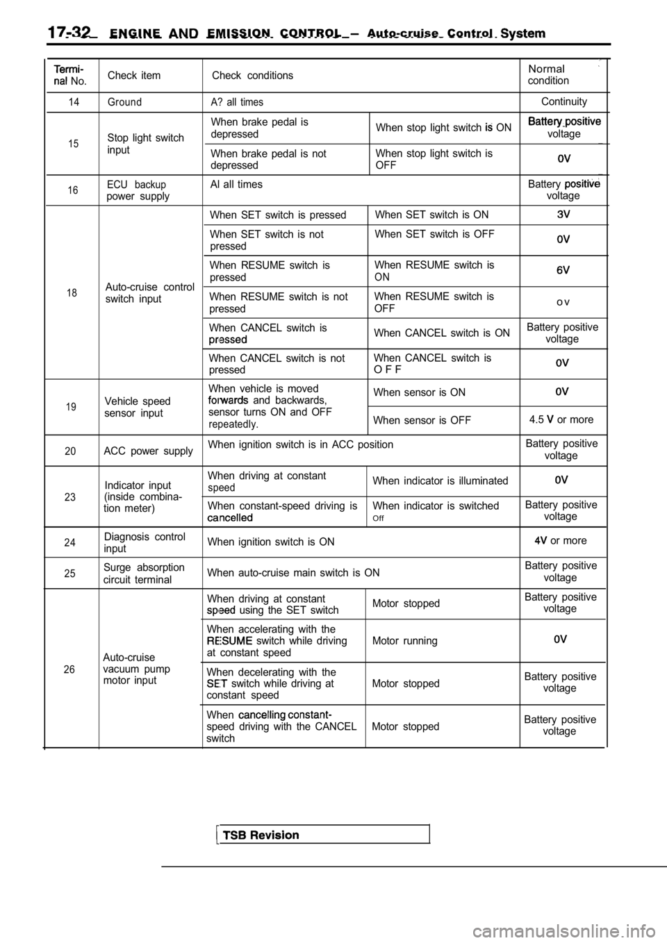
E N G I N E EMISSION CONTROL Auto-cruise Control
No.
14
15
Check item
Ground
Stop light switch
inputCheck conditions
A? all times
When brake pedal is
depressed
When brake pedal is not
depressed
Normal
condition
Continuity
When stop light switch ON voltage
When stop light switch is
OFF
16
18
19ECU backupAl all times Battery
power supply voltage
When SET switch is pressed When SET switch is ON
When SET switch is notWhen SET switch is OFF
pressed
When RESUME switch is When RESUME switch is
pressed
ONAuto-cruise control
switch input When RESUME switch is not
When RESUME switch is
pressed OFF
o v
When CANCEL switch is
When CANCEL switch is ONBattery positivevoltage
When CANCEL switch is not When CANCEL switch is
pressed
O F F
When vehicle is moved When sensor is ON
Vehicle speed and backwards,
sensor input sensor turns ON and OFF
repeatedly.When sensor is OFF
4.5 or more
20ACC power supplyWhen ignition switch is in ACC position
Battery positive
voltage
23
24
Indicator input
(inside combina-
tion meter)
Diagnosis control
input When driving at constantspeedWhen indicator is illuminated
When constant-speed driving is When indicator is swi
tchedBattery positive
Offvoltage
When ignition switch is ON
or more
25
26Surge absorption
circuit terminal
Auto-cruise
vacuum pump motor input When auto-cruise main switch is ON
When driving at constant
Motor stopped
using the SET switch
When accelerating with the
switch while driving Motor running
at constant speed
When decelerating with the
switch while driving at Motor stopped
constant speed
When
speed driving with the CANCEL Motor stopped
switch Battery positive
voltage
Battery positive voltage
Battery positivevoltage
Battery positive voltage