Page 782 of 2103
17-42ENGINE AND EMISSION CONTROL Auto-cruise Control System
CAUTION:Beforeremoval of air bag module and clock spring, refer t o the following sections:GROUP SRS Service Precautions.GROUP Air Bag Modules Clock Spring.
5.9 Nm4.3
41Nm30
2 8
Auto-cruise control switch and
clock spring
steps
27. Air bag module (Refer to GROUP
Bag
Modules and Clock Spring.)
28. Auto-cruise control
29. Steering wheel
30. Steering column upper cover
31. Steering column lower cover
l
under cover (Refer to
GROUP Panel.)
32. Clock spring (Refer to GROUP
Bag
Modules and Clock Spring.) 3 8
Sensor removal steps
33. Throttle position sensor
Engine (Turbo) and Engine>
34. Transaxle range switch
Engine (Non-turbo) 35. Park/neutral position switch Engine AA and Engine
36. Stop light switch
37. Clutch pedal position switch
Engine (Turbo) M/T and Engine 38. Vehicle speed sensor
Revision
Page 784 of 2103
ENGINE AND EMISSION CONTROL Auto-cruise System’,
AUTO-CRUISE CONTROL INDICATOR CHECK 17200190052
(1) Remove the combination meter.(Refer to GROUP 54
Combination meter.)
(2) Check the continuity between terminals (10) and (16).
If there is no continuity, replace the auto-cruise control
indicator.
CLOCK SPRING CHECK
Refer to GROUP Air Bag Module and Clock Spring.
THROTTLE POSITION SENSOR CHECK
Engine
(Turbo) and
Engine>17200290011
Refer to GROUP On-vehicle Service.
VEHICLE SPEED SENSOR CHECK
Engine
(Non-turbo) A/T>, INPUT SPEED SENSOR OR OUTPUT
SPEED SENSOR CHECK
Engine (Non-turbo)
Refer to GROUP 54 Combination Meter.
TSB Revision
Page 792 of 2103
ENGINE AND EMISSION CONTROL
ENGINE COOLANT TEMPERATURE SENSOR
AND INTAKE AIR TEMPERATURE SENSOR
To check these parts, refer to GROUP Troubleshooting.
AIR CONDITIONING SWITCH17300200031
To check the air conditioning switch, refer to GROU P 55
Air Conditioning Switch.
TSB Revision
Page 797 of 2103
Emission Control
AND EMISSION CONTROL
8. Measure the resistance between the solenoid terminals.
Standard value:
[at
CATALYTIC CONVERTER
GENERAL INFORMATION
The three-way catalytic converter, together with
the closed loop air-fuel ratio control (based on th e
oxygen sensor signal) oxidizes carbon monoxides
(CO) and hydrocarbons (HC), and reduces nitrogen
oxides
REMOVAL AND INSTALLATION
and Post-installation Operation
Under Cover Removal and Installation (Refer to
GROUP
Cover.) When the mixture is controlled at stoichiometric
air-fuel ratio, the three-way catalytic converter p
ro-
vides the highest purification against CO, HC, and
9.4
36
Removal steps
1. Heated oxygen sensor connector2. Front exhaust pipe
3. Gasket4. Catalytic 5. Gasket
TSB Revision
Page 808 of 2103
17-68ENGINEAND EMISSION CONTROL (Turbo) and
EVAPORATIVE EMISSION CONTROL, SYSTEM
GENERAL INFORMATION Engine (Turbo)>
The evaporative emission control system preventsWhen driving with a low to medium load on the
fuel vapors generated in the fuel tank from escapin gengine, the fuel vapor absorbed by the EVAP
into the atmosphere.ter is drawn into the port of the throttle body.
Fuel vapors from the fuel tank flow through the When driving with a high load on the engine, the
fuel tank pressure control valve and vapor pipe/hos
epurge control valve opens and the fuel vapor
to be stored temporarily in the canister.sorbed by the EVAP canister is drawn into the air
intake hose.
SYSTEM DIAGRAM
Check valve EVAP canister
To air
hoseintake
EVAP purge s o l e n o i d
Revision
Engine control
module
I1
Barometric pressure sensor
Intake air temperature sensor
Engine coolant temperature sensor
Volume air flow sensor
COMPONENT LOCATION
Evaporative emission purge solenoid
Page 809 of 2103

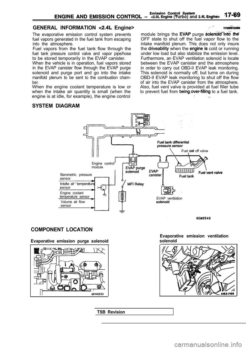
(Turbo) and
GENERAL INFORMATION Engine>
The evaporative emission control system prevents
fuel vapors generated in the fuel tank from escapin g
into the atmosphere.
Fuel vapors from the fuel tank flow through the
fuel tank pressure control valve and vapor pipe/hos e
to be stored temporarily in the EVAP canister.
When the vehicle is in operation, fuel vapors stored
in the EVAP canister flow through the EVAP purge
solenoid and purge port and go into the intake
manifold plenum to be sent to the combustion cham-
ber.
When the engine coolant temperature is low or
when the intake air quantity is small (when the
module brings the purge
OFF state to shut off the fuel vapor flow to the
intake manifold plenum. This does not only insure
the when the cold or running
under low load but also stabilize the emission leve l.
Furthermore, an EVAP ventilation solenoid is locate
between the EVAP canister and the atmosphere
in order to carry out OBD-II EVAP leak monitoring.
This solenoid is normally off, but turns on during
OBD-II EVAP leak monitoring to shut off the flow
of air into the EVAP canister from the atmosphere.
Also, fuel vent valve is provided at fuel filler tu be
to prevent fuel from to a fuel tank.
engine is at idle, for example), the engine control
SYSTEM DIAGRAM
Fuel off valve
Engine control
module
Barometric pressure
sensor
Intake air temperature
sensor
Engine coolant
temperature sensor
Volume air flow
sensorEVAP ventilation
COMPONENT LOCATION
Evaporative emission purge solenoid
Evaporative emission ventilation
solenoid
TSB Revision
Page 816 of 2103
AND C O N T R O L (Turbo) and Engine>
Valve
PURGE CONTROL VALVE Engine
1. Remove the purge control valve.
2. Connect a hand vacuum pump to the vacuum nipple of the purge control valve.
3.Apply a vacuum of 53 (16 and check
ness.
4.Blow in air lightly from the evaporative emission c anister
side nipple and check conditions as follows.
Hand vacuum pump vacu-
umNormal condition
0 (0 (No vacuumAir does not blow through
is applied)
27
(8.0 or more Air blow through
5. Connect a hand
vacuum pump to the positive pressure
nipple of the purge control valve.
6.Apply a vacuum of 53 (16 and check
ness.
Revision
VOLUME AIR FLOW SENSOR, ENGINE COOLANT
TEMPERATURE SENSOR AND INTAKE AIR
TEMPERATURE SENSOR
Refer to GROUP Troubleshooting.
AIR CONDITIONING SWITCH
Refer to GROUP 55 Air Conditioning Switch.
Page 820 of 2103

(Turbo) and Engine>
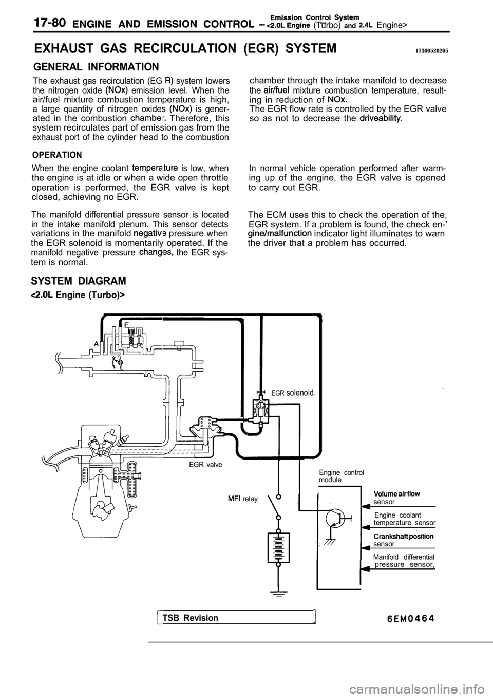
EXHAUST GAS RECIRCULATION
GENERAL INFORMATION
The exhaust gas recirculation (EG system lowers
the nitrogen oxide
emission level. When the
air/fuel mixture combustion temperature is high,
a large quantity of nitrogen oxides is gener-
ated in the combustion Therefore, this
system recirculates part of emission gas from the
exhaust port of the cylinder head to the combustion
OPERATION
When the engine coolant is low, when
the engine is at idle or when a wide open throttle
operation is performed, the EGR valve is kept
closed, achieving no EGR.
The manifold differential pressure sensor is locate d
in the intake manifold plenum. This sensor detects
variations in the manifold pressure when
the EGR solenoid is momentarily operated. If the
manifold negative pressure the EGR sys-
tem is normal.
SYSTEM DIAGRAM
Engine (Turbo)>
(EGR) SYSTEM17300520205
chamber through the intake manifold to decrease
the mixture combustion temperature, result-
ing in reduction of
The EGR flow rate is controlled by the EGR valve
so as not to decrease the
In normal vehicle operation performed after warm-
ing up of the engine, the EGR valve is opened
to carry out EGR.
The ECM uses this to check the operation of the, EGR system. If a problem is found, the check en-’
indicator light illuminates to warn
the driver that a problem has occurred.
EGR valve
relay
EGRsolenoid
Engine control
module
Isensor
Engine coolant
temperature sensor
sensor
Manifold differential
TSB Revision
pressure sensor,