Page 1095 of 2103
AUTOMATIC TRANSAXLE
ENGINE (TURBO) AND ENGINE> On-vehicle Service
23100170047
1. Drain out the automatic transmission fluid.
2. Remove the oil pan.
3. Remove the oil filter.
4. Remove the oil temperature sensor.
5.Press the solenoid valve harness grommet and connec tor
into the transaxle case.
6.Press the catches of the solenoid valve harness grommets
and pass the connector through the case hole.
7.Remove the valve body assembly. The manual
come out, so be careful not to drop it.
valve can
Page 1097 of 2103
AUTOMATIC TRANSAXLE
ENGINE (TURBO) AND ENGINE>
12. Temporarily install valve body
pin in the valve, groove.
oil sensor arid holder and tighten bolts
with the specified torque.,
A bolt: 18 mm long
bolt: 25 mm in.) long
bolt: 40 mm (1.57 long
body assembly mounting ,
1 1 N m ( 8 . 0
13. Install oil filter.
14. Install a new oil pan gasket and pan.
15. Pour in the specified amount of ATF.
16.. Perform the oil pressure test. Readjust if nec essary.
TSB Revision
Page 1108 of 2103

AUTOMATIC TRANSAXLE
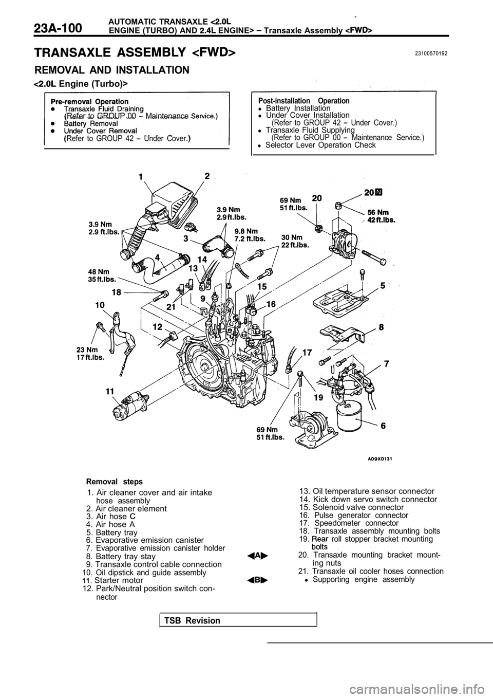
ENGINE (TURBO) AND ENGINE> Transaxle Assembly
23100570192
REMOVAL AND INSTALLATION
Engine (Turbo)>
(Refer to GROUP 00 Maintenance
(Refer to GROUP 42 Under Cover.)
Post-installation Operationl Battery Installationl Under Cover Installation(Refer to GROUP 42 Under Cover.)l Transaxle Fluid Supplying(Refer to GROUP 00 Maintenance Service.)l Selector Lever Operation Check
Removal steps
1. Air cleaner cover and air intakehose assembly2. Air cleaner element
3. Air hose
4. Air hose A5. Battery tray
6. Evaporative emission canister
7. Evaporative emission canister holder
8. Battery tray stay
9. Transaxle control cable connection
10. Oil dipstick and guide assembly Starter motor
12. Park/Neutral position switch con-
nector
13. Oil temperature sensor connector
14. Kick down servo switch connector
15. Solenoid valve connector
16. Pulse generator connector
17. Speedometer connector
18. Transaxle assembly mounting bolts
19.
roll stopper bracket mounting
20. Transaxle mounting bracket mount-
ing nuts21. Transaxle oil cooler hoses connectionl Supporting engine assembly
TSB Revision
Page 1110 of 2103

AUTOMATICTRANSAXLE
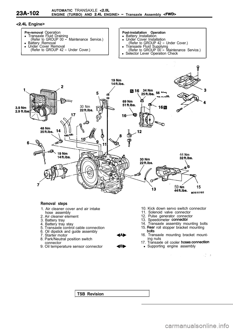
ENGINE (TURBO) AND ENGINE> Transaxle Assembly
Engine>
Pre-removalOperationl Transaxle Fluid Draining(Refer to GROUP 00 Maintenance Service.)l Battery Removall Under Cover Removal(Refer to GROUP 42 Under Cover.)I
I
I
Post-installation Operationl Battery Installationl Under Cover Installation(Refer to GROUP 42 Under Cover.)l Transaxle Fluid Supplying(Refer to GROUP 00 Maintenance Service.)l Selector Lever Operation Check
30 Nm
5915
44Nm
TSB Revision
Removal steps
1. Air cleaner cover and air intakehose assembly2. Air cleaner element
3. Battery tray
4. Battery tray stay
5. Transaxle control cable connection
6. Oil dipstick and guide assembly7. Starter motor
8. Park/Neutral position switch
connector9. Oil temperature sensor connector
10. Kick down servo switch connector11. Solenoid valve connector
12. Pulse generator connector
13. Speedometer
14. Transaxle assembly mounting bolts
15. roll stopper bracket mounting
16. Transaxle mounting bracket mount-
ing nuts17. Transaxle oil cooler l Supporting engine assembly
Page 1114 of 2103

AUTOMATIC TRANSAXLE
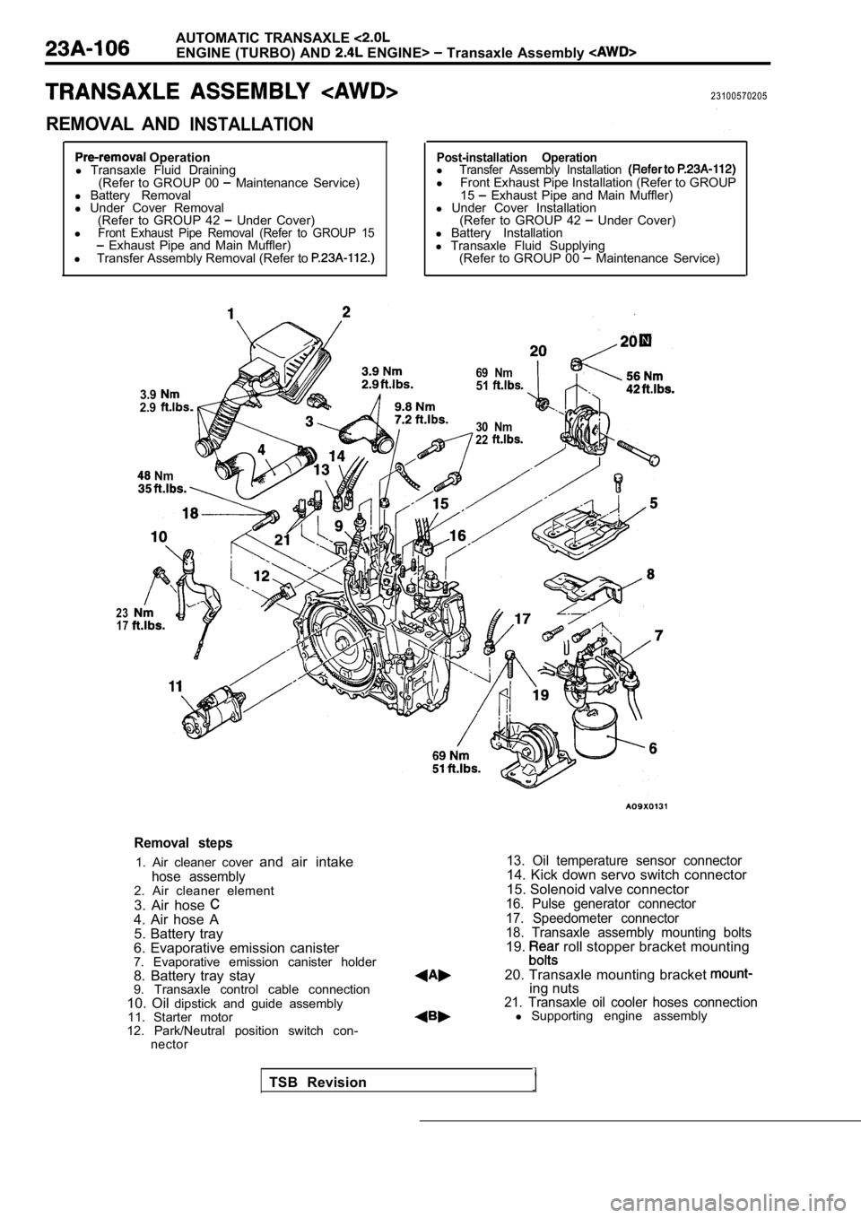
ENGINE (TURBO) AND ENGINE> Transaxle Assembly
REMOVAL ANDINSTALLATION
23100570205
Operation
l Transaxle Fluid Draining
(Refer to GROUP 00
Maintenance Service)
l Battery Removal
l Under Cover Removal
(Refer to GROUP 42
Under Cover)
lFront Exhaust Pipe Removal (Refer to GROUP 15 Exhaust Pipe and Main Muffler)
l Transfer Assembly Removal (Refer to
3.92.9
Nm
Post-installation OperationlTransfer Assembly Installation l Front Exhaust Pipe Installation (Refer to GROUP
15 Exhaust Pipe and Main Muffler)
l Under Cover Installation
(Refer to GROUP 42
Under Cover)
l Battery Installation
l Transaxle Fluid Supplying
(Refer to GROUP 00
Maintenance Service)
30 Nm
22
23 17
69 Nm51
Removal steps
1. Air cleaner cover and air intake
hose assembly2. Air cleaner element
3. Air hose
4. Air hose A
5. Battery tray
6. Evaporative emission canister
7. Evaporative emission canister holder
8. Battery tray stay
9. Transaxle control cable connection
10. Oil dipstick and guide assembly
11. Starter motor
12. Park/Neutral position switch con- nector
13. Oil temperature sensor connector14. Kick down servo switch connector
15. Solenoid valve connector
16. Pulse generator connector
17. Speedometer connector
18. Transaxle assembly mounting bolts
19. roll stopper bracket mounting
20. Transaxle mounting bracket
ing nuts21. Transaxle oil cooler hoses connectionl Supporting engine assembly
TSB Revision
Page 1124 of 2103
AUTOMATIC TRANSAXLE
ENGINE (NON-TURBO)? General
SECTIONAL VIEW
Case
Input speedOverdrive
clutch Reverse clutch
sensor
2-4 clutchUnderdrive
clutch
L o w / R e v e r s eclutch converter
Torqueconverter
.sensor
Oil pump
TSB Revision
shaft
gear
gear
Differential
Page 1125 of 2103
AUTOMATIC TRANSAXLE T o o l s
ItemS t a n d a r d v a l u e .Resistance of input speed sensor ..Resistance of output speed sensor
Resistance of solenoid coil [at Approx. 1
Resistance of solenoid coil [at
Resistance of OD solenoid coil [at A p p r o x . 1
Resistance of UD solenoid coil [at .
Distance between detent pin and detent plate mm (in.)
Installation dimension of front roll stopper bracket assembly mm (in.)
ItemSpecified lubricantQuantity (qts.)
Transaxle fluid DIAMOND ATF SP II or equivalent8.6(9.1)
Scan tool (MUT-II)
Steering linkage puller knuckle removal
lLateral lower arm ball joint
and knuckle removal
lCompression lower arm balljoint and knuckle removal
Revision
Page 1128 of 2103

AUTOMATIC TRANSAXLE ENGINE (NON-TURBO)> Troubleshooting
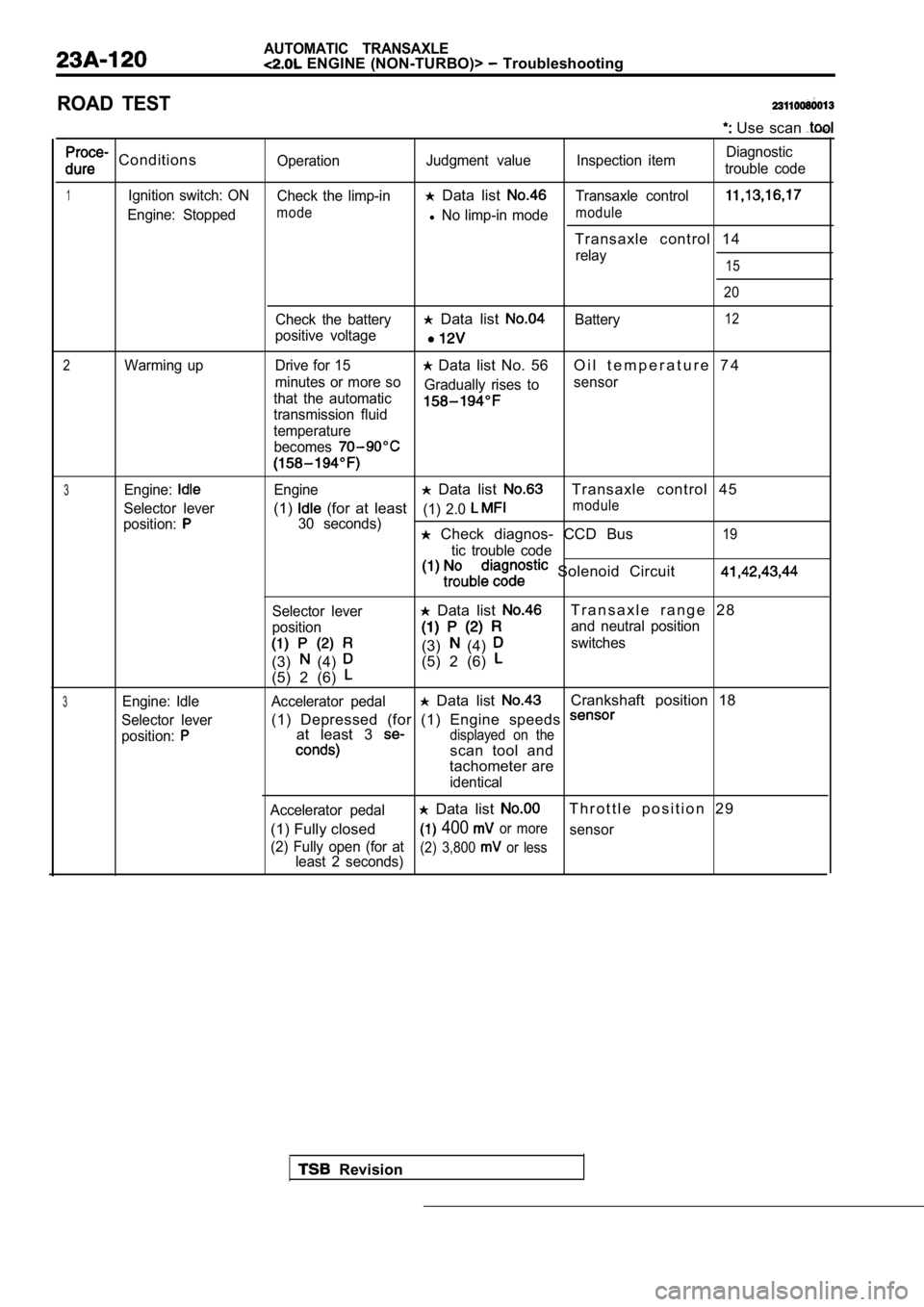
ROAD TEST
Use scan
ConditionsOperationJudgment value Inspection item Diagnostic
trouble code
1Ignition switch: ON Check the limp-in Data list Transaxle control
Engine: Stoppedmodel No limp-in modemodule
Transaxle control 14
relay15
20
Check the battery Data list Battery12
positive voltage
2Warming up Drive for 15 Data list No. 56 O i l t e m p e r a t u r e 7 4
minutes or more so
that the automatic Gradually rises to
sensor
transmission fluid
temperature
becomes
3Engine:Engine Data list Transaxle control 45
Selector lever(1) (for at least(1) 2.0 module
position:30 seconds) Check diagnos- CCD Bus19
tic trouble code
Solenoid Circuit
Selector lever
position
(3) (4)
(5) 2 (6)
Data list T r a n s a x l e r a n g e 2 8
and neutral position
(3) (4) switches
(5) 2 (6)
3Engine: Idle Accelerator pedal Data list Crankshaft position 18
Selector lever(1) Depressed (for (1) Engine speeds
position:at least 3 displayed on the
scan tool and
tachometer are
identical
Accelerator pedal
Data list T h r o t t l e p o s i t i o n 2 9
(1) Fully closed
400 or moresensor
(2) Fully open (for at least 2 seconds)
(2) 3,800 or less
Revision