Page 1332 of 2103
AUTOMATIC TRANSAXLE
OVERHAUL -Transaxle
(8) Remove the oil filter from the
(9) Remove the 10 valve body mounting bolts.
the oil temperature sensor holder and remove
the oil temperature sensor harness from the clamp.
the finger of the solenoid valve grommet,
push the grommet into the case and ‘remove the valv e
body assembly.
out the oil temperature sensor.
the parking roller support.
the set screw of the control shaft and
remove the manual control shaft assembly.
the detent plate.
TSB Revision
Page 1356 of 2103

AUTOMATIC TRANSAXLE
OVERHAUL -Transaxle
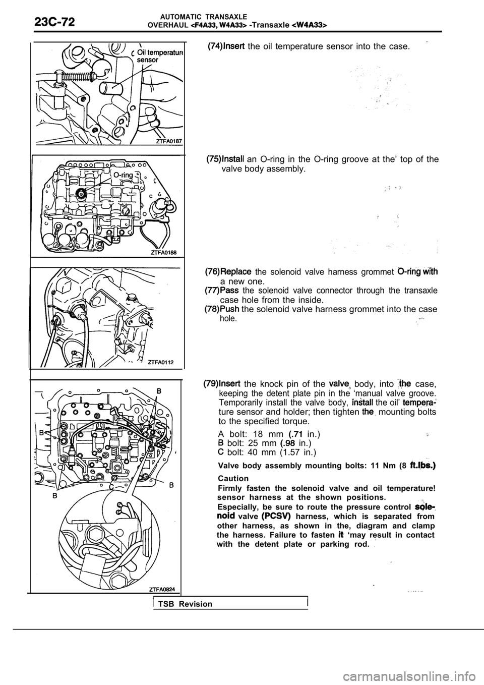
the oil temperature sensor into the case.
an O-ring in the O-ring groove at the’ top of the
valve body assembly.
the solenoid valve harness grommet
a new one.
the solenoid valve connector through the transaxle
case hole from the inside.
the solenoid valve harness grommet into the case
hole.
the knock pin of the body, into case,
keeping the detent plate pin in the ‘manual valve g roove.
Temporarily install the valve body,
the oil’
ture sensor and holder; then tighten mounting bolts
to the specified torque.
A bolt: 18 mm
in.)
bolt: 25 mm in.)
bolt: 40 mm (1.57 in.)
Valve body assembly mounting bolts: 11 Nm (8
Caution
Firmly fasten the solenoid valve and oil temperatur e!
sensor harness at the shown positions.
Especially, be sure to route the pressure control
valve harness, which is separated from
other harness, as shown in the, diagram and clamp
the harness. Failure to fasten
‘may result in contact
with the detent plate or parking rod.
TSB Revision
Page 1404 of 2103
AUTOMATIC TRANSAXLE OVERHAUL General Information
G E N E R A L I N F O R M A T I O N
The four-speed FWD transaxle uses fully-adaptive Adaptive are those which
perform their functions based on real-time feedback sensor
The t&axle uses hydraulically
applied clutches to shift a planetary gear train.
SECTIONAL VIEW
Casec l u t c h
sensor
Torque converterclutch ,
Reverse
Outputspeed sensor
gear set
Revision
gear
shaftgear
Differential
Page 1417 of 2103
AUTOMATIC TRANSAXLE OVERHAUL Transaxle
adjustable
.
(11) Put a dab of petrolatum on the top of low/reve rse,
accumulator piston. Using a
bar or,
equivalent, press the bar evenly against the
so it sticks to the piston. Pull piston’.
two return springs.
input shaft end play before disassembly Will
usually indicate when a No. 4 thrust plate
is
required (except when major parts are
No. 4 thrust plate is the overdrive
hub.
Attach a dial indicator to transaxle its
plunger seated against end of input shaft.
Move input shaft in and out to obtain end
reading.
End play specifications are
to 0.64 mm to
inch.). Record indicator reading for reference
reassembling the. transaxle.
input speed sensor.
TSB Revision
Page 1446 of 2103
AUTOMATIC TRANSAXLE OVERHAUL Transaxle
f r o n t s u n g e a r a s s e m b l y .
Front sun assembly
shaft
Oil
determine the proper thickness thrust
plate, select the thinnest No. 4 “test” thrust plat e; Using,
to hold thrust in position,, install input
clutches assembly. Be sure the ‘input assembly
is completely seated.
Caution
if view through input speed sensor hole is not as
shown above, the input
assembly is not
seated
the oil pump O-ring. You can install and remove
the oil pump and gasket very easily to
No. 4 thrust plate..Caution
Be sure to install O-ring on oil
the proper No. 4 thrust plate.
Temporarily secure oil pump 2 oil bolts.
Insert a bolt into end of input shaft.
Measure input shaft end play.
If end play readings are not within
the transaxle assembly. will be damaged.
.
TSBRevision
Page 1467 of 2103
(4) Remove, valve body attaching bolts (18).
I
Manual
shaft
seal
(5) Using a screwdriver, push park sprag rollers aw ay from
guide bracket.
(6)Remove valve body.
(7) Remove transaxle range sensor
screw.
(8) Remove manual shaft seal.
TSB Revision
Page 1468 of 2103
Transaxlerange
sensor
clutchcheck
Retainers
(9) Slide transaxle range sensor up the manual shaf t and
remove.,
(lO)Remove accumulator retaining plate screws (2).
Remove the upper valve body.
(ll)Remove separator plate from transfer plate. Rem ove O/D
clutch check ball and oil screen.
.
thermal valve.
check balls and retainers.
Check ball 75
TSB Revision
Page 1510 of 2103
26-6FRONT AXLE Front
FRONT HUB ASSEMBLY
REMOVAL AND INSTALLATION
88 Nm65
8885
Removal steps
1. Cotter pin 2. Drive shaft nut
3. Front wheel speed sensor
with 4. Caliper assembly
5. Brake disc
A l
Nut
Nm
145-188
5
Caution
6. Upper
7. Front hub.
The front hub assembly not be disassembled..
REMOVAL SERVICE POINTS
DRIVE SHAFT R E M O V A L .
CALIPER ASSEMBLY REMOVAL
Secure the removed caliper so that it
does not fall., ,
ARM BALL JOINT AND KNUCKLE
DISCONNECTION
Caution
1.Using the tool, loosen the tie rod end mounting
nut. Only loosen the nut; do not remove it from the
joint.
2.Support the tool with a cord, etc. to prevent
it from coming off.
TSB Revision