Page 1170 of 2103
AUTOMATIC TRANSAXLE
ENGINE (NON-TURBO)> On-vehicle Service
Transaxle range sensor.(with built-in oil temperature sensor)
TSB Revision
Page 1171 of 2103
AUTOMATIC TRANSAXLE
ENGINE (NON-TURBO)>: On-vehicle _ _
AUTOMATIC
COMPONENT CHECK
SPEED SENSOR
(1) Disconnect the input speed sensor connector.
(2) Measure the resistance
the input speed
side connector terminals 1 and 2.
Standard value:,
(3) If the resistance is outside the standard value , replace
the input speed sensor.
OUTPUT SPEED SENSOR CHECK
(1) Disconnect the output speed sensor connector.
(2) Measure the resistance between the input speed
side connector terminals 1 2.
Standard value:
(3) If the resistance is outside the standard value , replace
the output speed sensor.
TRANSAXLE RANGE SENSOR CONTINUITY CHECK
Refer to
OVERDRIVE SWITCH CONTINUITY CHECK
Refer to
POSITION SENSOR (TPS) CHECK
Refer to GROUP On-vehicle Inspection of Compo-
nents.
ENGINE COOLANT TEMPERATURE SENSOR CHECK
.
Refer to GROUP On-vehicle Inspection of
nents.
CRANKSHAFT CHECK
Refer to GROUP Troubleshooting.
ABSOLUTE PRESSURE SENSOR
Refer to On-vehicle Inspection of
nents.
Revision
Page 1174 of 2103

AUTOMATIC TRANSAXLE
ENGINE (NON-TURBO)> On-vehicle Service
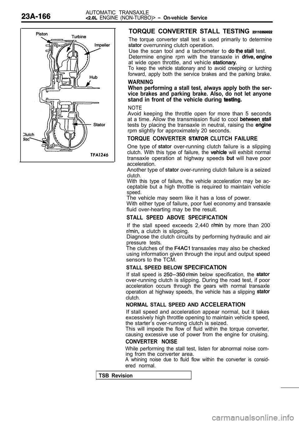
TORQUE CONVERTER STALL TESTING
The torque converter stall test is used primarily to determine
overrunning clutch operation.
Use the scan tool and a tachometer to
test.
Determine engine rpm with the transaxle in
at wide open throttle, and vehicle
To keep the vehicle stationary and to avoid creepin g or lurching
forward, apply both the service brakes and the parking brake.
WARNING
When performing a stall test, always apply both the ser-
vice brakes and parking brake. Also, do not let any one
stand in front of the vehicle during
NOTE
Avoid keeping the throttle open for more than 5 seconds
at a time. Allow the transmission fluid to cool
tests by placing the transaxle in neutral, raising the
rpm slightly for approximately 20 seconds.
TORQUE CONVERTER CLUTCH FAILURE
One type of over-running clutch failure is a slipping
clutch. With this type of failure, the will exhibit normal
transaxle operation at highway speeds will have poor
acceleration.
Another type of over-running clutch failure is a seized
clutch.
With this type of failure, the vehicle acceleration may be ac-
ceptable but a high throttle is required to maintai n vehicle
speed.
The vehicle may seem like it has a loss of power.
With either type of failure, poor fuel economy and transaxle
fluid over-hearting may be the result.
STALL SPEED ABOVE SPECIFICATION
If the stall speed exceeds 2,440 by more than 200
a clutch is slipping.
Diagnose the clutch circuits by performing hydrauli c and air
pressure tests.
The clutches of the transaxles may also be checked
using information given through the input and outpu t speed
sensors to the TCM.
STALL SPEED BELOW SPECIFICATION
If stall speed is below specification, the
over-running clutch is slipping. During the road te st, if poor
acceleration occurs through the gears with normal t ransaxle
operation at highway speeds, the vehicle has a slip ping
clutch.
NORMAL STALL SPEED AND ACCELERATION
If stall speed and acceleration appear normal, but it takes
excessively high throttle opening to maintain vehic le speed,
the starter’s over-running clutch is seized.
This will impede the flow of fluid within the torqu e converter,
causing excessive use of power from the engine for cruising.
CONVERTER NOISE
While performing the stall test, listen for abnormal noise com-
ing from the converter area.
A whining noise due to fluid flow within the conver ter is consid-
ered normal.
TSB Revision
Page 1200 of 2103

AUTOMATIC TRANSAXLE
ENGINE (NON-TURBO)> Transaxle Assembly
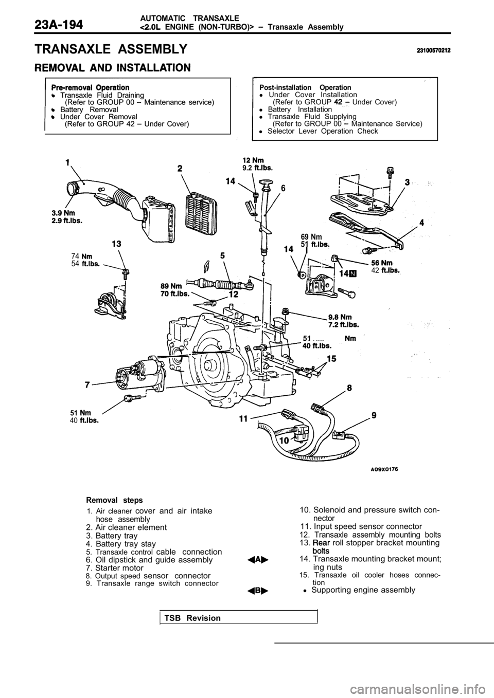
TRANSAXLE ASSEMBLY
l Transaxle Fluid Draining
l Transaxle Fluid Draining
(Refer to GROUP 00 Maintenance service)
(Refer to GROUP 00 Maintenance service)
l Battery Removal
l Battery Removal
l Under Cover Removal
l Under Cover Removal
(Refer to GROUP 42
Under Cover)
(Refer to GROUP 42 Under Cover)
7454
Post-installation Operationl Under Cover Installation
(Refer to GROUP Under Cover)
l Battery Installation
l Transaxle Fluid Supplying
(Refer to GROUP 00
Maintenance Service)
l Selector Lever Operation Check
9.2
6
5140
69 Nm51 I
42
51
Removal steps
1. Air cleaner cover and air intake
hose assembly2. Air cleaner element
3. Battery tray
4. Battery tray stay 5. Transaxle control cable connection
6. Oil dipstick and guide assembly
7. Starter motor
8. Output speed sensor connector
9. Transaxle range switch connector
10. Solenoid and pressure switch con-
nector11. Input speed sensor connector
12. Transaxle assembly mounting bolts13. roll stopper bracket mounting
14. Transaxle mounting bracket mount; ing nuts
15. Transaxle oil cooler hoses connec- tion
l Supporting engine assembly
TSB Revision
Page 1221 of 2103
39.
40.
41.
44:
45.
46.
47.
50.
51.
52. 53.
Pulse generatorSpring washerControl lever
ClampPark/neutral position switch
Oil temperature sensor
End clutch cover
O-ring
BearingEnd clutch
Thrust washer
End clutch hub
Thrust bearing
End clutch shaftBearing retainer
Snap ring Lock plate
54. Idler gear shaft55. Bearing inner race’
56. Idler gear
57. Bearing inner race
58. Spacer
59. Snap ring .60. servo switch
61. servo piston
62. Spring
63. Anchor rod64. flange
65. Transfer shaft
66. Outer race
67. Gasket . .
,
68. O-ring
6 9 . V a l v e b o d y
TSB Revision
Page 1223 of 2103
A U T O M A T I C T R A N S A X L EOVERHAUL Transaxle
the snap ring and remove
switch.
(8) Remove the oil pan and oil gasket.
(9) Remove the oil filter.
the oil temperature sensor bracket. mounting
bolts’and remove the oil temperature sensor from brack-
et. Using a screwdriver, push out the rubber plug,
from inside the case, and remove the oil temperatur e
sensor from the case..
(11) With their catches pressed down, force the har
ness grom-
met and connector into the transaxle case:,
TSB Revision
Page 1304 of 2103
AUTOMATIC TRANSAXLE
OVERHAUL,
(8) Remove the oil filter from the valve body.
.
,
(9) Remove the 10 valvebody mounting
the oil temperature sensor holder and
oil temperature sensor clamp,
,
the finger of the solenoid valve harness grommet,,
push the grommet into and remove the valve
body assembly.
out the oil temperature sensor.
the parking roller
I-
*
the set screw of the manual shaft and’
remove the manual control shaft
the detent plate.
--. .
TSB Revision
Page 1325 of 2103
AUTOMATIC
OVERHAUL Transaxle
A
the oil temperature sensor into the
,
an O-ring in the O-ring groove at the top of ‘the
valve body assembly.
the solenoid valve harness grommet with
valve connector transaxle
case hole from the inside,
the solenoid valve harness the case
hole.
the knock pin of the valve body
keeping the detent plate pin in the manual groove.
Temporarily install the valve body,
the oil tempera-
ture sensor and holder; then tighten the
to the specified torque.
A 1 8
bolt: 40 mm (1.58 in.)
body assembly mounting 11
Caution
Firmly fasten the and temperature
sensor harness at the shown positions.
Especially, be sure to route the pressure
(PCSV) harness, which is separated from
other harness, as shown in the diagram and
the harness. Failure to fasten it may result in con tact
with the detent plate or parking rod.
TSB Revision