Page 1057 of 2103

AUTOMATIC TRANSAXLE
ENGINE (TURBO) AND ENGINE> Troubleshooting
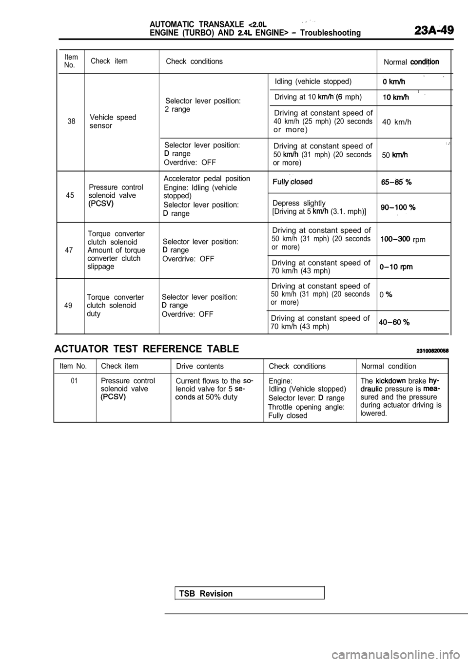
Item
No. Check itemCheck conditions
Normal
Idling (vehicle stopped)
Driving at 10 mph)Selector lever position:
2 range
Vehicle speedDriving at constant speed of
38 40 km/h (25 mph) (20 seconds40 km/hsensoro r m o r e )
Selector lever position:Driving at constant speed of range50 (31 mph) (20 seconds50Overdrive: OFF
or more)
Accelerator pedal position
Pressure control Engine: Idling (vehicle
45solenoid valvestopped)
Selector lever position: Depress slightly
range[Driving at 5 (3.1. mph)]
47
49
Torque converter
clutch solenoid
Amount of torque
converter clutch
slippage
Torque converter
clutch solenoid
duty Selector lever position:
range
Overdrive: OFF
Selector lever position:
range
Overdrive: OFF
Driving at constant speed of
50 km/h (31 mph) (20 seconds rpmor more)
Driving at constant speed of
70 km/h (43 mph)
Driving at constant speed of
50 km/h (31 mph) (20 seconds0or more)
Driving at constant speed of
70 km/h (43 mph)0
ACTUATOR TEST REFERENCE TABLE
Item No.Check item Drive contents
01Pressure controlCurrent flows to the
solenoid valve lenoid valve for 5
at 50% duty
Check conditions
Engine:
Idling (Vehicle stopped)
Selector lever:
range
Throttle opening angle: Fully closed
Normal condition
The brake
pressure is
sured and the pressure
during actuator driving is
lowered.
TSB Revision
Page 1060 of 2103

AUTOMATIC TRANSAXLE
ENGINE (TURBO) AND ENGINE> Troubleshooting
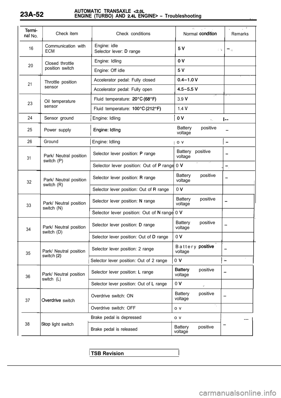
No.Check item
Check conditionsNormalRemarks
16Communication withEngine: idle
ECMSelector lever: range
20Closed throttle
position switch Engine: Idling
Engine: Off idle
21
23
24
25
26
31
32
33
34
35
36
37
38
Throttle position
sensor Accelerator pedal: Fully closed
Accelerator pedal: Fully open
Oil temperature
sensor Fluid temperature:
Fluid temperature:
3.9
1.4
Sensor ground Engine: IdlingI--
Power supplyBattery positive
voltage
Ground Engine: IdlingIo v
Park/ Neutral position
Selector lever position: rangeBattery positive
switch (P) voltage
Selector lever position: Out of range 0
Park/ Neutral position
Selector lever position: rangeBattery positive
switch (R) voltage
Selector lever position: Out of
range0
Park/ Neutral position Selector lever position: rangeBattery positive
switch (N) voltageSelector lever position: Out of range 0
Park/ Neutral position
Selector lever position: rangeBattery positive
switch (D) voltage
Selector lever position: Out of
range0
Park/ Neutral position Selector lever position: 2 rangeB a t t e r y
switchvoltage
Selector lever position: Out of 2 range 0
Park/ Neutral position
Selector lever position: range positive
switch (L)voltage
Selector lever position: Out of
range0
switch Overdrive switch: ON
Overdrive switch: OFF
Battery positive
voltage
o v
Brake pedal is depressedo v--- I
light switch Brake pedal is releasedBattery positive voltage
TSB Revision
Page 1061 of 2103
AUTOMATIC TRANSAXLE
ENGINE AND ENGINE> Troubleshooting
No. Check item
Check conditionsNormal condition
39
40Backup power supply Ignition switch: OFFBattery positive
voltage
Vehicle speed sensor Vehicle: Slowly moving forwardFlashing
Measure between terminals (41) and
41Pulse generator
(PG-B)
(42)Engine: 3,000
Selector lever position: range
Transaxle condition:
gear
Measure between terminals (41) and
42Pulse generator (42)
(PG-B)Engine: 3,000
Selector lever position: range
Transaxle condition:
gear
43Pulse generator A
(PG-A) Measure between terminals (43) and(44)Engine: 3,000
Selector lever position: range
Transaxle condition:
gear,
Measure between terminals (43) and
Pulse generator A
44Engine: 3,000 (PG-A) Selector lever position: range
Transaxle condition:
gear
45 GroundEngine: Idlingo v
46Ignition pulse Engine: 3000
TSB Revision
Page 1062 of 2103
AUTOMATIC TRANSAXLE
ENGINE. (TURBO) AND ENGINE> Troubleshooting
Checkitem
PulseCheck conditions
Selector lever position: range
Overdrive: OFF
Normal
Driving at constant speed of 50
mph) (20 seconds or
more)
W a v e f o r m A
PulseSelector lever position: range
Overdrive: OFF
Vehicle
speed Selector lever position: range
sensor Overdrive: OFF
at constant speed of 50
mph) (20 seconds or Waveform
more)
Driving at constant speed of 50
mph) (20 seconds or Waveform
m o r e )
Pressure
controlAccelerator pedal position .
solenoid
Engine: Idling (vehicle stopped)
Fully closed Waveform
valveSelector lever position: range
,
WAVEFORM SAMPLE
Waveform AWaveform
.
5
0
TSB Revision
,
WaveformWaveform
2
1
0
-1
- 2
0
-10
-20
Page 1066 of 2103
AUTOMATIC: TRANSAXLE
ENGINE AND On-vehicle Service
switch
Name
Data link connector
servo switch
OD-OFF switch
Oil temperature sensor
Oil temperature sensor
Park/neutral position switch
Revision
I
Page 1067 of 2103
AUTOMATIC TRANSAXLE ‘I
ENGINE (TURBO) AND On-vehicle Service I-
Pulsegene-rator
Pulsegene-rator A
Throttle position sensor(with closed throttle position switch) Vehicle
sensor
CC Solenoid
Revision
Page 1069 of 2103
AUTOMATIC TRANSAXLE
ENGINE (TURBO) AND On-vehicle Servide
PULSE GENERATOR A CHECK
1. Disconnect the pulse generator A connector
2. Measure the resistance between the
generator
side connector terminals and 2.
Standard
3. If the resistance is outside the replace
the pulse generator assembly.. .
PULSE GENERATOR CHECK
1. Disconnect the pulse generator connector.
2. Measure the resistance between the
generator
side connector terminals 3 and 4.
Standard [at
3.If the resistance is outside- the standard replace
the pulse generator assembly.
PARK/ NEUTRAL POSITION SWITCH CONTINUITY CHECK
Refer to
OVERDRIVE SWITCH CONTINUITY CHECK23100330032
Refer to
THROTTLE POSITION SENSOR (TPS) CHECK
Refer to GROUP On-vehicle Inspection of Compo-
nents.
CLOSED THROTTLE POSITION SWITCH CHECK
Refer to GROUP inspection of
nents.
TSB Revision
Page 1070 of 2103

AUTOMATIC TRANSAXLE
ENGINE (TURBO) AND ENGINE> On-vehicle Service
Revision
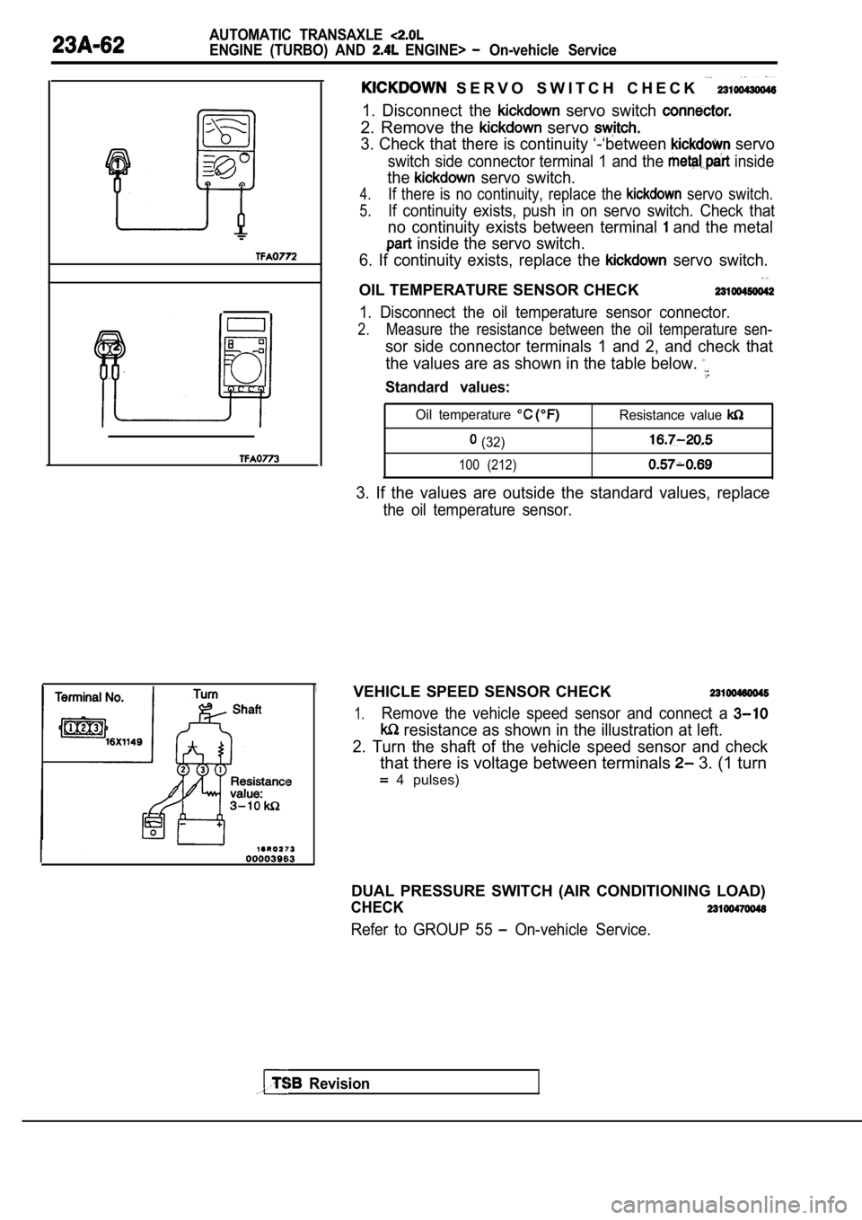
S E R V O S W I T C H C H E C K
1. Disconnect the servo switch
2. Remove the servo
3. Check that there is continuity ‘-‘between servo
switch side connector terminal 1 and the inside
the servo switch.
4.If there is no continuity, replace the servo switch.
5.If continuity exists, push in on servo switch. Check that
no continuity exists between terminal and the metal
inside the servo switch.
6. If continuity exists, replace the
servo switch.
OIL TEMPERATURE SENSOR CHECK
1. Disconnect the oil temperature sensor connector.
2.Measure the resistance between the oil temperature sen-
sor side connector terminals 1 and 2, and check that
the values are as shown in the table below.
Standard values:
Oil temperature Resistance value
(32)
100 (212)
3. If the values are outside the standard values, r eplace
the oil temperature sensor.
VEHICLE SPEED SENSOR CHECK
1.Remove the vehicle speed sensor and connect a
resistance as shown in the illustration at left.
2. Turn the shaft of the vehicle speed sensor and c heck
that there is voltage between terminals 3. (1 turn
4 pulses)
DUAL PRESSURE SWITCH (AIR CONDITIONING LOAD)
CHECK
Refer to GROUP 55 On-vehicle Service.