Page 821 of 2103
ENGINE AND EMISSION CONTROL Engine (Turbo) end
Engine>
COMPONENT LOCATION
Engine (Turbo)>
EGR solenoid
Manifold differential pressure sensor
relayEngine
module
EGR valve
Page 828 of 2103
Emission Control System ENGINE AND EMISSION CONTROL Engine (Turbo) and
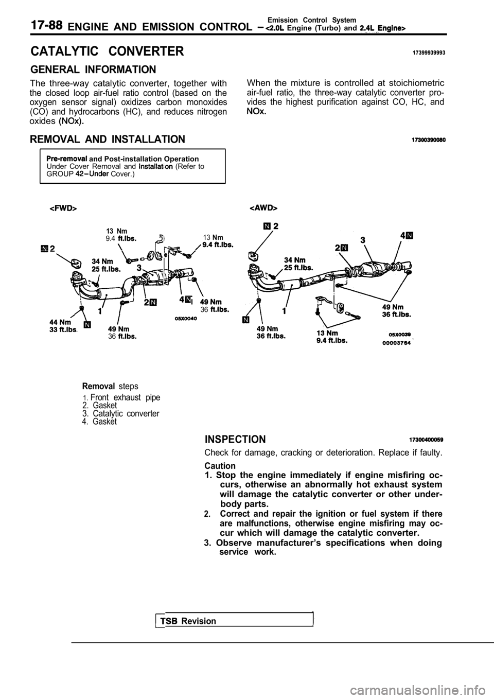
CATALYTIC CONVERTER17399939993
GENERAL INFORMATION
The three-way catalytic converter, together with
the closed loop air-fuel ratio control (based on the
oxygen sensor signal) oxidizes carbon monoxides
(CO) and hydrocarbons (HC), and reduces nitrogen
oxides
REMOVAL AND INSTALLATION
When the mixture is controlled at stoichiometric
air-fuel ratio, the three-way catalytic converter p ro-
vides the highest purification against CO, HC, and
and Post-installation Operation
Under Cover Removal and (Refer to
GROUP Cover.)
13 Nm9.413Nm
I36
. .
Revision
36
Removalsteps
1.Front exhaust pipe2. Gasket3. Catalytic converter4. Gasket
INSPECTION
Check for damage, cracking or deterioration. Replac e if faulty.
Caution
1. Stop the engine immediately if engine misfiring oc-
curs, otherwise an abnormally hot exhaust system
will damage the catalytic converter or other under- body parts.
2.Correct and repair the ignition or fuel system if t here
are malfunctions, otherwise engine misfiring may oc -
cur which will damage the catalytic converter.
3. Observe manufacturer’s specifications when doing
service work.
Page 870 of 2103
MANUAL TRANSAXLE
ENGINE AND ENGINE> Transaxle
TRANSAXLE
REMOVAL AND INSTALLATION
Pre-removal Operationl Transaxle Oil Draining (Refer to GROUP 00 Maintenance Service.)l Removal
l Under Cover Removal
(Refer to GROUP 42
Under Cover.)
Engine>
Post-installation Operationl Supplying Transaxle Oil (Refer to GROUP 00 Maintenance Service.)l Shift Lever Operation Check
l Speedometer Operation Check
l Under Cover Installation
(Refer to GROUP 42
Under Cover.)
l Battery installation
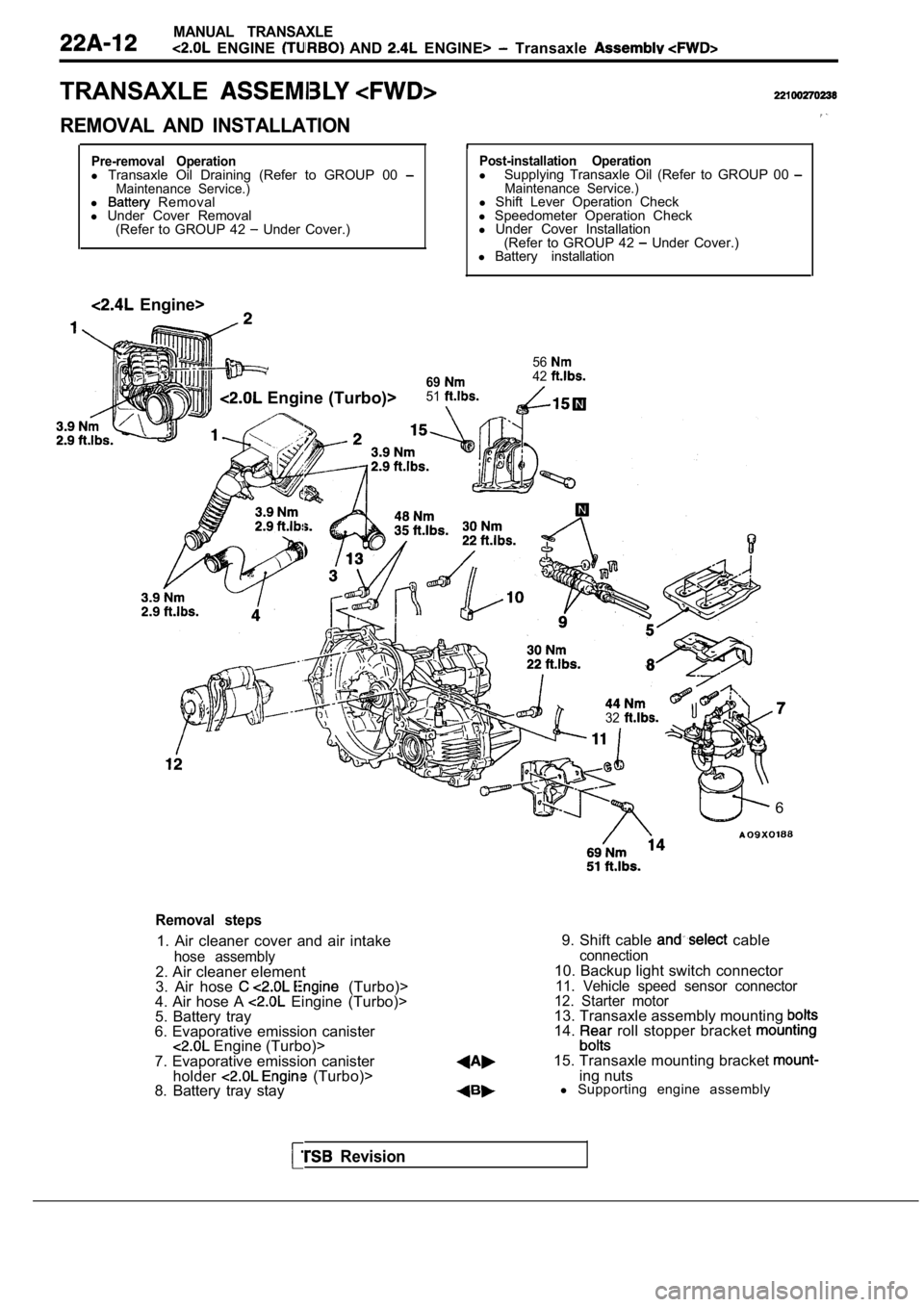
56
6942
Engine (Turbo)>51
32
6
Removal steps
1. Air cleaner cover and air intake
hose assembly2. Air cleaner element
3. Air hose (Turbo)>
4. Air hose A Eingine (Turbo)>
5. Battery tray
6. Evaporative emission canister
Engine (Turbo)>
7. Evaporative emission canister holder
(Turbo)>
8. Battery tray stay 9. Shift cable
cableconnection10. Backup light switch connector11. Vehicle speed sensor connector
12. Starter motor
13. Transaxle assembly mounting 14. roll stopper bracket
15. Transaxle mounting bracket ing nuts
l Supporting engine assembly
Revision
Page 874 of 2103
MANUAL ,
ENGINE AND Transaxle Assembly .
TRANSAXLE ASSEMBLY
REMOVAL INSTALLATION
22100270092
Pre-removal Operation
Transaxle Oil Draining to GROUP 00 Maintenance Service.)l Battery Removal
l Under Cover Removal
(Refer to GROUP 42
Under Cover.)
l Transfer Assembly Removal (Refer to
3.9 Nm
4
2.9
Post-installation Operation
l Supplying Transaxle Oil (Refer to GROUP 00
Maintenance Service.)l Shift Lever Operation Check
l Speedometer Operation Check
Transfer Assembly Installation (Refer to l Under Cover Installation
(Refer to GROUP 42 Under Cover.)
l Installation
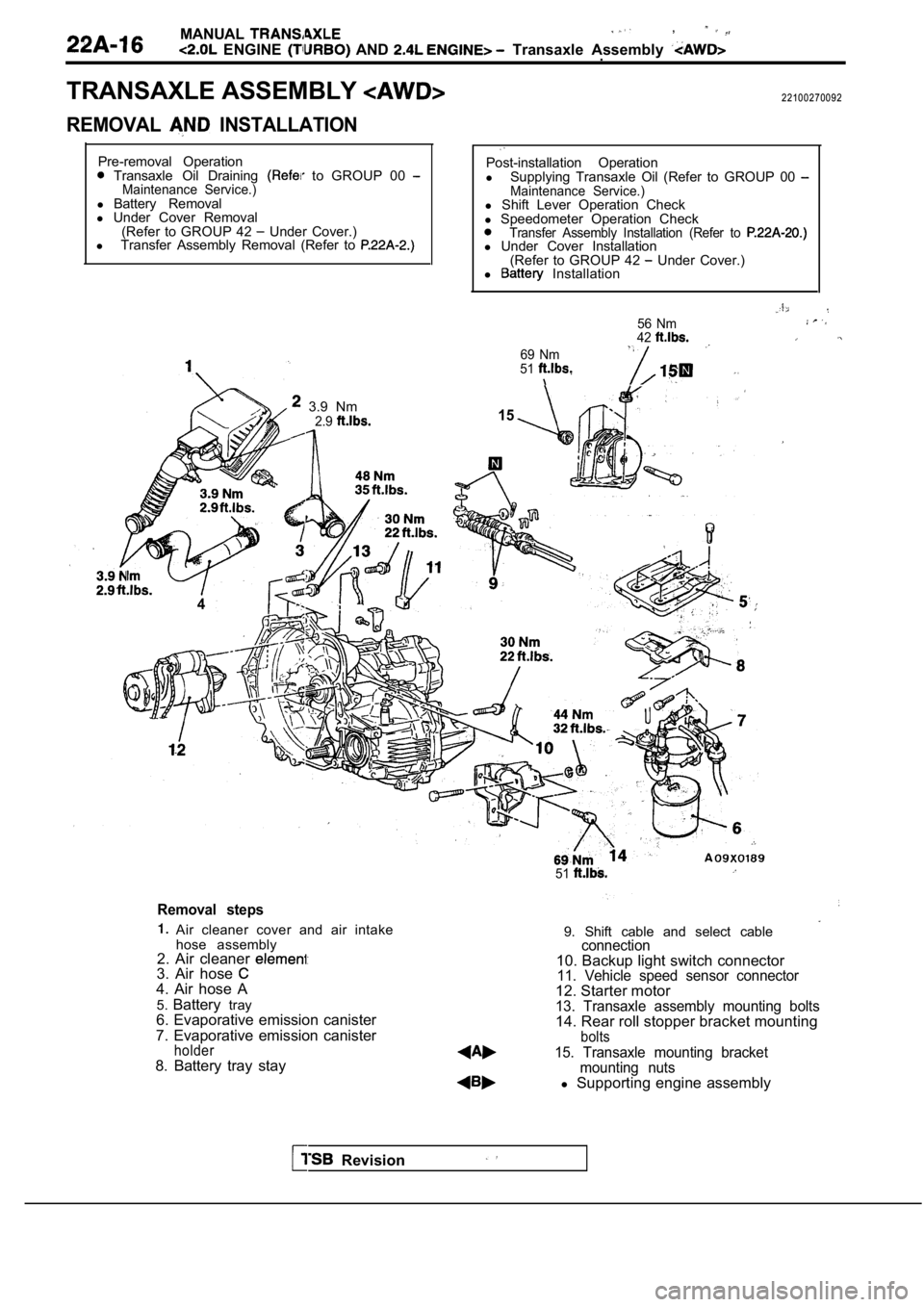
69 Nm
51
56 Nm
42
15
51
Removal steps
Air cleaner cover and air intake
hose assembly
2. Air cleaner
3. Air hose 4. Air hose A
5. Battery tray
6. Evaporative emission canister
7. Evaporative emission canister
holder8. Battery tray stay 9. Shift cable and select cable
connection10. Backup light switch connector11. Vehicle speed sensor connector12. Starter motor13. Transaxle assembly mounting bolts14. Rear roll stopper bracket mountingbolts
15. Transaxle mounting bracket
mounting nuts
l Supporting engine assembly
Revision
Page 886 of 2103
MANUAL TRANSAXLE
ENGINE (NON-TURBO)> Transaxle Control
TRANSAXLE ASSEMBLY
REMOVAL AND INSTALLATION
l Transaxle Oil Draining (Refer to GROUP 00
(Refer to GROUP 42 Under Cover.)
Post-installation Operationl
Supplying Transaxle Oil (Refer to GROUP 00 Maintenance Service.)l Shift Lever Check
l Speedometer ‘Operation Check
l Under Cover Installation
(Refer to GROUP 42
Under Cover.) I n s t a l l a t i o n
8
54Nm
Removal steps
1. Air cleaner cover and air intakehose assembly2. Air cleaner element
3. Battery tray
4. Battery tray stay
5. Shift cable and select cable
connection6. Backup light connectorl b
7. Vehicle speed sensor connector
8. Starter motor
9.
roll stopper bracket mounting
10. Transaxle mounting bracket
mounting nuts
l Supporting engine assembly
Revision
Page 1009 of 2103
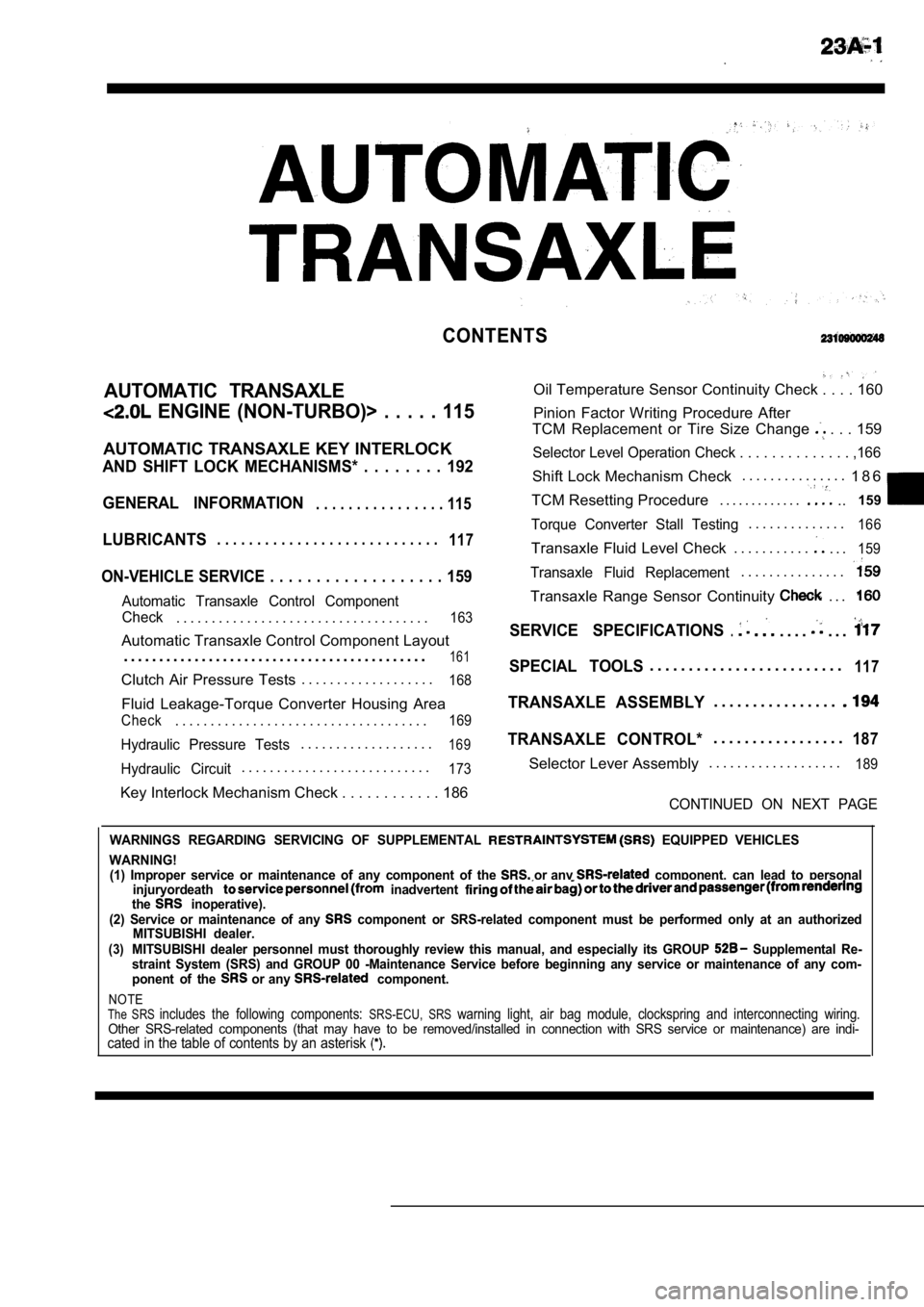
CONTENTS
AUTOMATIC TRANSAXLE
ENGINE (NON-TURBO)> . . . . . 115
AUTOMATIC TRANSAXLE KEY INTERLOCK
AND SHIFT LOCK MECHANISMS* . . . . . . . . 192
GENERAL INFORMATION
. . . . . . . . . . . . . . . . 115
LUBRICANTS. . . . . . . . . . . . . . . . . . . . . . . . . . . .117
ON-VEHICLE SERVICE . . . . . . . . . . . . . . . . . . . 159
Automatic Transaxle Control Component
Oil Temperature Sensor Continuity Check . . . . 160
Pinion Factor Writing Procedure After
TCM Replacement or Tire Size Change
. . . 159
Selector Level Operation Check . . . . . . . . . . . . . . ,166
Shift Lock Mechanism Check. . . . . . . . . . . . . . .
1 8 6
TCM Resetting Procedure . . . . . . . . . . . . .
..159
Torque Converter Stall Testing. . . . . . . . . . . . . .166
Transaxle Fluid Level Check . . . . . . . . . . .. . .159
Transaxle Fluid Replacement. . . . . . . . . . . . . . .
Transaxle Range Sensor Continuity . . .
Check. . . . . . . . . . . . . . . . . . . . . . . . . . . . . . . . . . . .163SERVICE SPECIFICATIONS.. . . .. . .Automatic Transaxle Control Component Layout
. . . . . . . . . . . . . . . . . . . . . . . . . . . . . . . . . . . . . . . . . . .
161SPECIAL TOOLS. . . . . . . . . . . . . . . . . . . . . . . . .117Clutch Air Pressure Tests . . . . . . . . . . . . . . . . . . .168
Fluid Leakage-Torque Converter Housing Area
Check. . . . . . . . . . . . . . . . . . . . . . . . . . . . . . . . . . . .169
Hydraulic Pressure Tests. . . . . . . . . . . . . . . . . . .169
Hydraulic Circuit. . . . . . . . . . . . . . . . . . . . . . . . . . .173
TRANSAXLE ASSEMBLY. . . . . . . . . . . . . . . .
TRANSAXLE CONTROL*. . . . . . . . . . . . . . . . .187
Selector Lever Assembly. . . . . . . . . . . . . . . . . . .189
Key Interlock Mechanism Check . . . . . . . . . . .
. 186CONTINUED ON NEXT PAGE
WARNINGS REGARDING SERVICING OF SUPPLEMENTAL EQUIPPED VEHICLES
WARNING! (1) Improper service or maintenance of any componen t of the
or any component, can lead to personal
injuryordeath inadvertent the inoperative).
(2) Service or maintenance of any component or SRS-related component must be perform ed only at an authorized
MITSUBISHI dealer.
(3)MITSUBISHI dealer personnel must thoroughly review this manual, and especially its GROUP Supplemental Re-
straint System (SRS) and GROUP 00 -Maintenance Serv ice before beginning any service or maintenance of any com-
ponent of the
or any component.
NOTEThe SRS includes the following components: SRS-ECU, SRS warning light, air bag module, clockspring and inte rconnecting wiring.Other SRS-related components (that may have to be removed/installed in connection with SRS service or maintenance) are indi-cated in the table of contents by an asterisk
Page 1016 of 2103
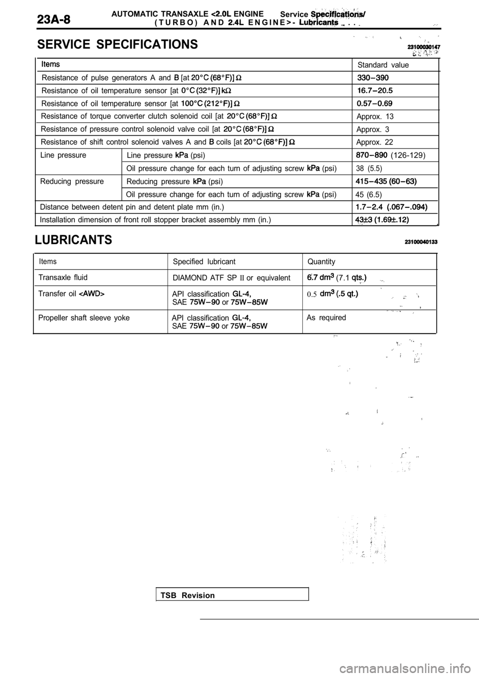
AUTOMATIC TRANSAXLE ENGINEService
( T U R B O ) A N D E N G I N E > - . .
SERVICE SPECIFICATIONS
Standard value
Resistance of pulse generators A and
[at
Resistance of oil temperature sensor [at
Resistance of oil temperature sensor [at
Resistance of torque converter clutch solenoid coil [at Approx. 13
Resistance of pressure control solenoid valve coil [at
Approx. 3
Resistance of shift control solenoid valves A and
coils [at Approx. 22
Line pressure Line pressure
(psi) (126-129)
Oil pressure change for each turn of adjusting scre w (psi)38 (5.5)
Reducing pressure
Reducing pressure (psi)
Oil pressure change for each turn of adjusting scre w (psi)
45 (6.5)
Distance between detent pin and detent plate mm (in .)
Installation dimension of front roll stopper bracket assembly mm (in.)
LUBRICANTS
Items
Transaxle fluid
Transfer oil
Propeller shaft sleeve yoke Specified lubricant
Quantity
DIAMOND ATF SP
IIor equivalent (7.1
API classification 0.5SAE or ,
API classification As required
SAE
or
TSB Revision
Page 1020 of 2103
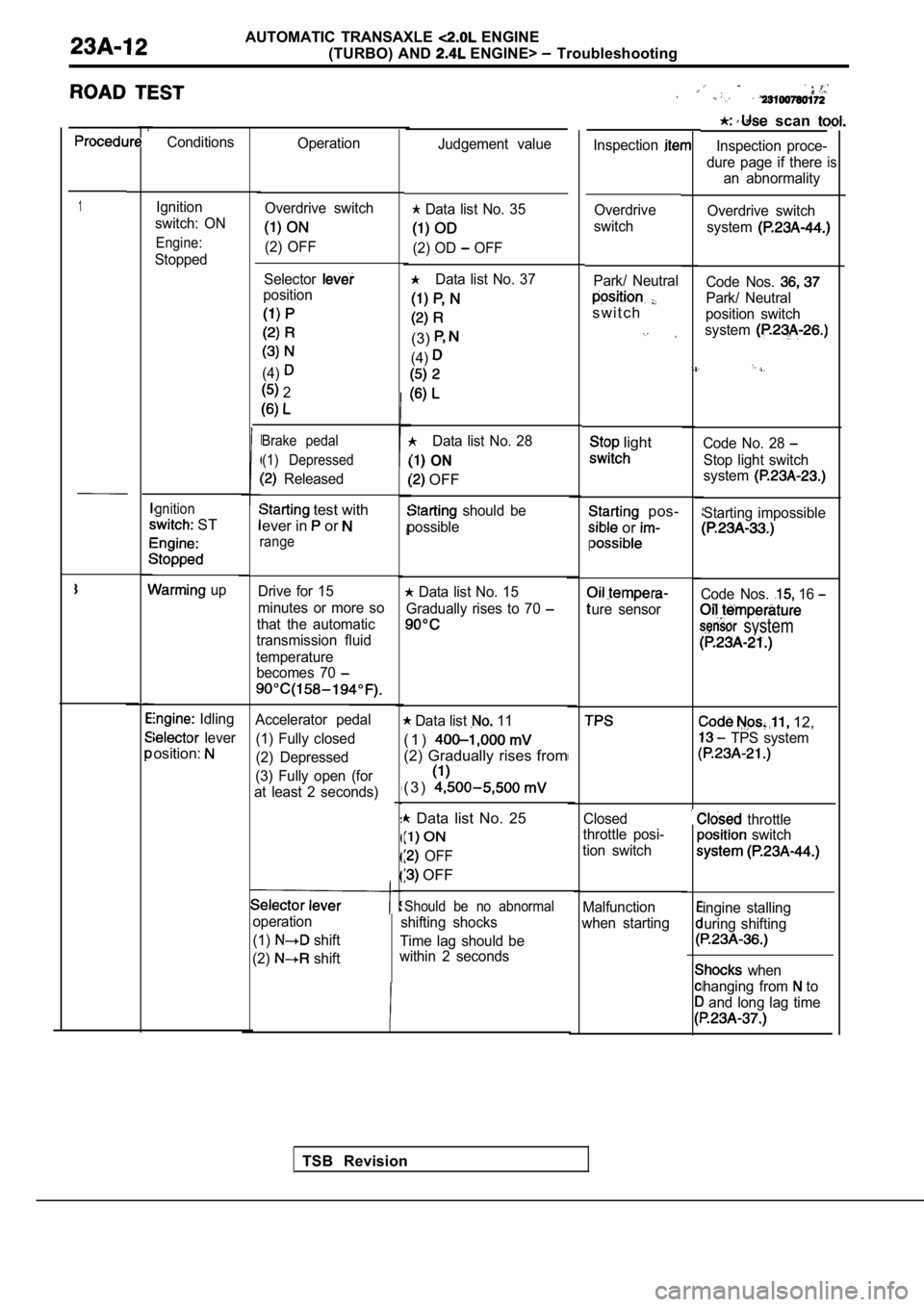
AUTOMATIC TRANSAXLE ENGINE
(TURBO) AND
ENGINE> Troubleshooting
scan
Inspection proce-
dure page if there an abnormality
is
Conditions Operation
Inspection
1Ignition
switch: ON
Engine:
Stopped
gnition
ST
up
Idling
lever
osition:
Judgement value
Overdrive switch
system
Code Nos.
Park/ Neutral
position switch
system
Code No. 28
Stop light switch
system
Starting impossible
Code Nos. 16
system
12,
TPS system
throttle switch
ingine stalling
uring shifting
when
hanging from
to
and long lag time
Overdrive switch
(2) OFF
Data list No. 35
(2) OD OFF
Data list No. 37
(3)
(4)
Data list No. 28
ON
OFF
should be
possible Overdrive
switch
Selector
position
(4)
2
Park/ Neutral
s w i t c h
Brake pedal (1) Depressed
Released
light
pos-
or
I
ure sensor
test with
ever in
or
range
Drive for 15
minutes or more so
that the automatic
transmission fluid
temperature becomes 70 Data list No. 15
Gradually rises to 70
Accelerator pedal
(1) Fully closed
(2) Depressed
(3) Fully open (for
at least 2 seconds) Data list 11
( 1 )
(2) Gradually rises from
( 3 )
Data list No. 25
OFF
OFF
Closed
throttle posi-
tion switch
Should be no abnormal
shifting shocks
Time lag should be
within 2 seconds Malfunction
when starting
operation
(1)
shift
(2)
shift
TSB Revision