Page 685 of 2103
FUEL SUPPLY Fuel Tank
Valve closed
Valve opened
Toport A To
INSPECTION
FUEL TANK FILLER TUBE
Engine (Non-turbo)
(1) Connect a clean rubber hose to the port
tank filler tube assembly.
(2) Blow air into the hose. Check that the air flow s out of
the port B.
(3) Use a screwdriver or similartool to close the valve. Blow
air into the hose in this condition. Check that the
not flow out of the port B.,
FUEL TANK DIFFERENTIAL PRESSURE SENSOR
CHECK
Engine>
(1) Disconnect the fuel tank differential
connector and connect the special tool
terminals of the disconnected connector.
(2) Turn the ignition switch to ON and take a readi ng of
the following output voltage. Between terminals (2)
(3)
Standard value: 2.0 3.0
FUEL CUT OFF VALVE CHECK
If the sound of the float valve moving (knocking so und) can
be heard when the valve assembly is gently shaken u p and
down, then the valve is okay.
FUEL GAUGE UNIT CHECKRefer to GROUP 54
Combination Meter.
TSB Revision
Page 721 of 2103
INTAKE AND EXHAUST Intake Manifold Engine
REMOVAL AND INSTALLATION
Operationl Residual Fuel Pressure Releasing(Refer to GROUP Service.)l Engine Coolant Draining(Refer to GROUP Service.)l Reservoir Assembly Removal with Auto-Cruise
2.9
Post-installation Operationl Reservoir Assembly Installation
l Engine Coolant Supplying (Refer to GROUP Service.)l Accelerator Cable Adjustment (Refer to GROUP 17 On-vehicle Service.)
3.92 . 9
O-ring
Engineoil
Removalsteps
1. Air intake hose2.Breather hose
3. Accelerator cable connection
4. Clip5. MAP sensor connector
6. Charge temperature sensor connector
7. Vacuum hose connection
8.TPS connector9. motor connector 10.
wiring harness11. connection
12. PCV hose assembly 13. Vacuum hose connection14. Brake booster hose
connection
15. pipe connection
16. fuel hose connection
TSB Revision
Page 725 of 2103

INTAKE AND EXHAUST Intake Manifold Engine
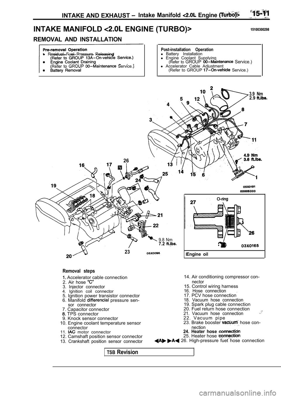
INTAKE MANIFOLD ENGINE (TURBO)>15100300298
REMOVAL AND INSTALLATION
l Residual Fuel Pressure Releasing
(Refer to GROUP
Service.)
26
Post-installation Operationl Battery Installation
l Engine Coolant Supplying
(Refer to GROUP Service.)l Accelerator Cable Adjustment
(Refer to GROUP Service.)
3.9 Nm2.9
9.8 Nm7.2
23
Removal steps
Accelerator cable connection
2. Air hose
3. Injector connector4. Ignition coil connector 5. Ignition power transistor connector
6. Manifold
pressure sen-sor connector
14. Air conditioning compressor con-
7. Capacitor connector
TPS connector
9. Knock sensor connector
10. Engine coolant temperature sensor
connector11. motor connector
12. Camshaft position sensor connector
13. Crankshaft position sensor connector nector
15. Control wiring harness16. Hose connection.17. PCV hose connection18. Vacuum hose connection19. Spark plug cable connection
20. Fuel return hose connection
21. Vacuum hose connection2 2 . V a c u u m p i p e
23. Brake booster hose con-
nection24. Heater hose 25. Heater hose 26. High-pressure fuet hose connection
IEngine oil
TSBRevision
Page 726 of 2103
I N T A K E A N D E X H A U S T Intake Manifold, Engine
,,
Nm
Nm
12-15
38
27-34 Nm
27. Fuel rail, fuel injector and pressureregulator assembly
28. Insulator
29. Insulator
30. Ignition power transistor
31. Ignition coil
32. EGR valve assembly 33. Intake manifold
Engine hanger
3 5 . I n t a k e
38. Intake manifold gasket37. Manifold sensor39. Charge air 39. Throttle
TSB Revision
Page 728 of 2103

INTAKE AND EXHAUST Intake Manifold
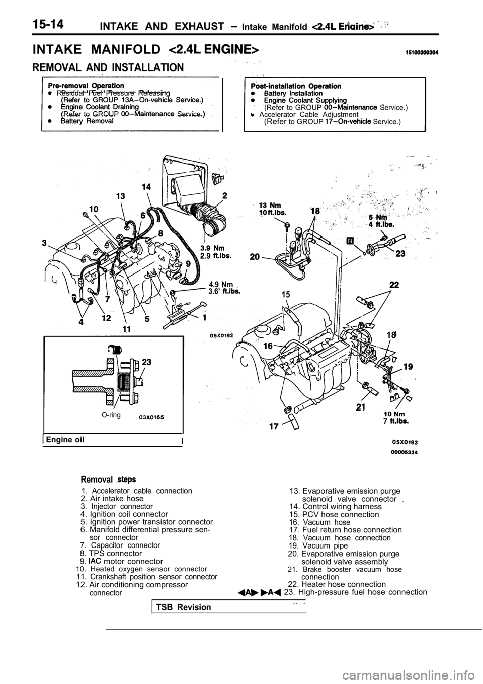
INTAKE MANIFOLD
REMOVAL AND INSTALLATION
l Residual Fuel Pressure Releasing
(Refer to GROUP
Service.) (Refer to GROUP Service.)
l Accelerator Cable Adjustment
(Refer to GROUP
Service.)
2.9
4.9 Nm 3.6’ 15
O-ring
Engine oilI
18
10 Nm7
Removal
1. Accelerator cable connection2. Air intake hose3. Injector connector4. Ignition coil connector
5. Ignition power transistor connector
6. Manifold differential pressure sen-
sor connector
7. Capacitor connector
8. TPS connector
9. motor connector
10. Heated oxygen sensor connector
11. Crankshaft position sensor connector12. Air conditioning compressor
connector
13. Evaporative emission purge
solenoid valve connector .
14. Control wiring harness
15. PCV hose connection
16. Vacuum hose17. Fuel return hose connection18. Vacuum hose connection
19. Vacuum pipe
20. Evaporative emission purge solenoid valve assembly
21. Brake booster vacuum hose
connection22. Heater hose connection 23. High-pressure fuel hose connection
TSB Revision
Page 729 of 2103
12 Nm8.7
q 26
3.6
9.8 Nm7.2
3 . 6
24. Fuel rail, fuel injector and pressureregulator assembly25. Insulator
26. Insulator
27. Manifold erential pressure sensor26. Ignition power transistor29. Spark plug cable connection
TSB Revision
30.Ignition coil
31. Intake manifold stay
32.Intake manifold33. Intake manifold gasket34. Throttle body35. EGR valve assembly
Page 732 of 2103
INTAKE AND EXHAUST Exhaust Manifold
E X H A U S T M A N I F O L D E N G I N E ( T U R B O ) >
REMOVAL AND INSTALLATION
Pre-removal and Post-installation OperationEngine Coolant Draining and Refilling
l Engine Oil Draining and Refilling
(Refer to GROUP 00
Maintenance Service.)
Nm
12-15 Nm8.8-11- - 1 6 ’
3
. .
Removal steps
1. Condenser fan motor assembly with air conditioning>
2. Heated oxygen sensor
3. Engine oil level gauge guide
4. Air cleaner and air intake hose
assembly5. Air hose (A) connection
6. Water hose connection
7. Water hose connection
8. Oil pipe (A) connection 9. Heat protector
A)
10. Heat protectorB)
11. Engine hanger
12. Front exhaust pipe connection 13. Flange bolts 14. Flange 15.
Coned disc spring .16. Exhaust -manifold17.Exhaust manifold gasket Ring19. Gasket (A)
TSB Revision
Page 733 of 2103
INTAKE AND EXHAUST Exhaust Manifold
24 ,
54-64 Nm
20. Vacuum hose assembly 21. Turbocharger assembly22. Oil return pipe
23. Water pipe assembly (B) 24. Oil pipe 25. Water pipe assembly (A)
26. manifold fitting27.Ghsket
REMOVAL SERVICE
HEATED OXYGEN SENSOR REMOVAL
TSB Revision
TURBOCHARGER ASSEMBLY
Remove the turbocharger
assembly with the exhaust fitting,
water pipe assembly (A), water pipe assembly (B) an d the
oil pipe assembly attached to it.
OIL PIPE ASSEMBLY REMOVAL
Caution
After disconnecting the oil pipe, take care that fo reign
materialdoesnotenter the oil passage hole of the turbo-
charger assembly.