Page 633 of 2103
ENGINE (TURBO)
AND
ENGINE> Troubleshooting
INSPECTION PROCEDURE USING AN ANALYZER
VOLUME AIR FLOW SENSOR
Measurement method
1. Disconnect the volume air flow sensor connector, and
connect the special tool (test harness: in be-
tween. (All terminals should be connected.)
2.Connect the analyzer special patterns pickup to volume
air flow sensor connector terminal 3.
Alternate method (lest harness not available)
1. Connect the analyzer special
pickup to ECM
terminal 90.
Standard Wave Pattern
Observation conditions
FunctionSpecial
Pattern height Low
Pattern selector Display
Engine
Standard wave pattern
The time (cycle time) is reduced when the amount of intake air increases.
Times and are equal.
0Time
TSB Revision
Page 634 of 2103
ENGINE (TURBO)
AND ENGINE> Troubleshooting . .
Observation conditions (pattern changes with engine changes.)
.
id
10--
0Time
Wave pattern observation points
Check to be sure that cycle time becomes shorter and the frequency increases when speed
is increased.
TSB Revision1
Examples of abnormal wave patterns
l Example 1
,Cause of problem
Sensor interface malfunction
Wave pattern characteristics
Rectangular wave pattern is output even when the en gine
is not started.
l Example 2
Cause of problem
Damaged rectifier or vortex generation column .
Wave pattern characteristics
Unstable wave pattern with non-uniform frequency. H ow-
ever, when an ignition leak occurs during acceleration,
the wave pattern will be distorted temporarily, eve n if
the volume air flow sensor is normal.
Page 635 of 2103

ENGINE (TURBO)
AND ENGINE>
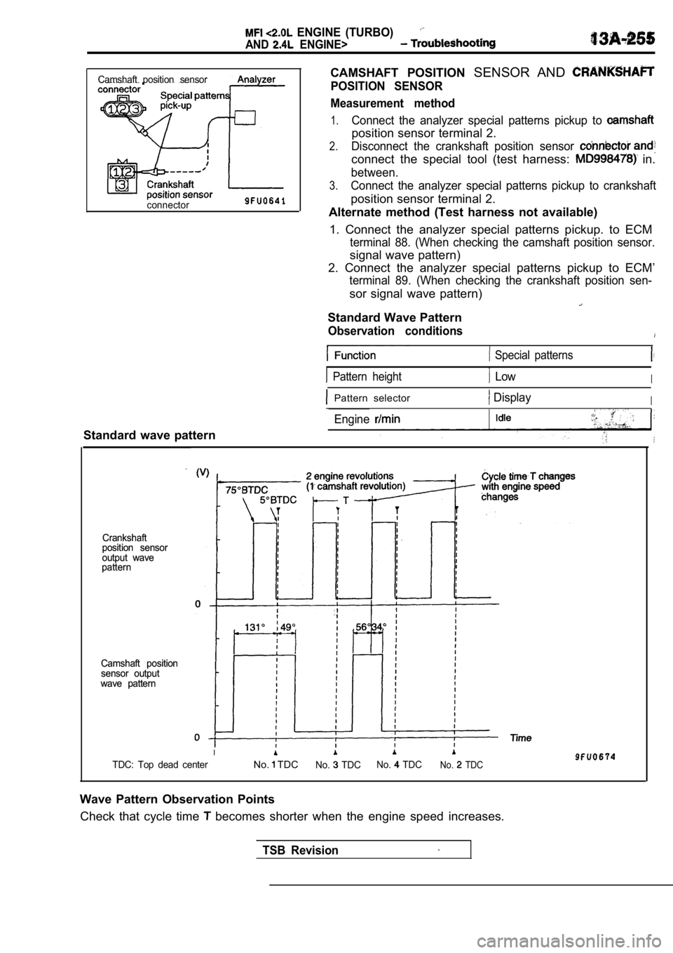
CAMSHAFT POSITION SENSOR AND
POSITION SENSOR
Measurement method
1.Connect the analyzer special patterns pickup to
position sensor terminal 2.
2.Disconnect the crankshaft position sensor
connect the special tool (test harness: in.
between.
3.Connect the analyzer special patterns pickup to cra nkshaft
position sensor terminal 2.
Alternate method (Test harness not available)
1. Connect the analyzer special patterns pickup. to ECM
terminal 88. (When checking the camshaft position sensor.
signal wave pattern)
2. Connect the analyzer special patterns pickup to ECM’
terminal 89. (When checking the crankshaft position sen-
sor signal wave pattern)
Standard Wave Pattern
Observation conditions
Camshaft position sensor
connector
Standard wave pattern
Crankshaft
Crankshaft
position sensor
position sensor
output wave
output wave
pattern
pattern
Camshaft position
Camshaft position
sensor output
sensor output
wave pattern
wave pattern
Special patterns
Pattern height LowI
Pattern selector DisplayI
Engine
I
TDC: Top dead centerNo. TDCNo. TDC No. TDCNo. TDC
Wave Pattern Observation Points
Check that cycle time
becomes shorter when the engine speed increases.
TSB Revision
Page 636 of 2103

ENGINE (TURBO)
AND
ENGINE> Troubleshooting
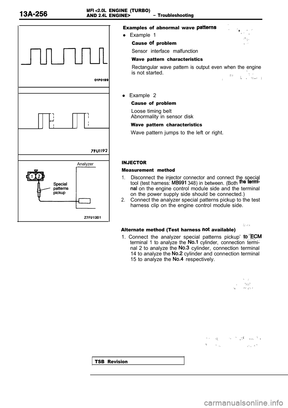
Analyzer
Examples of abnormal wave ,
l Example 1
Cause problem
Sensor interface malfunction
Wave pattern characteristics
Rectangular wave pattern is output even when the en gine
is not started.
l Example 2
Cause of problem
Loose timing belt
Abnormality in sensor disk
Wave pattern characteristics
Wave pattern jumps to the left or right.
INJECTOR
Measurement method
1.Disconnect the injector connector and connect the s pecial
tool (test harness:
348) in between. (Both
on the engine control module side and the terminal
on the power supply side should be connected.)
2.Connect the analyzer special patterns pickup to the test
harness clip on the engine control module side.
Alternate method (Test harness available)
1. Connect the analyzer special patterns pickup’
terminal 1 to analyze the cylinder, connection termi-
nal 2 to analyze the cylinder, connection terminal
14 to analyze the
cylinder and connection terminal
15 to analyze the
respectively.
TSB Revision
Page 643 of 2103

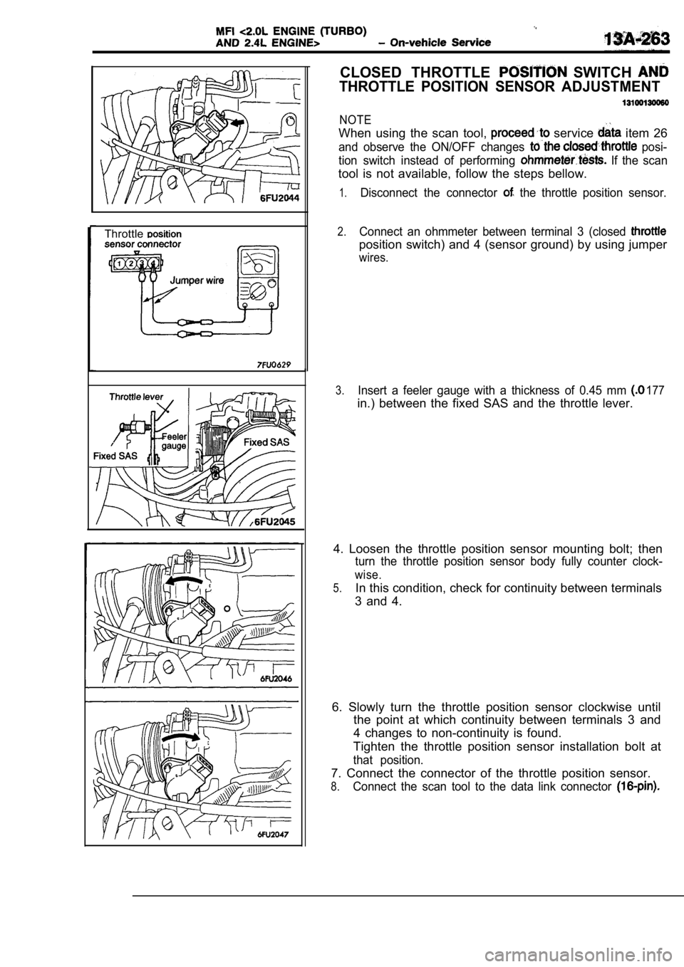
Throttle
CLOSED THROTTLE SWITCH
THROTTLE POSITION SENSOR ADJUSTMENT
NOTE
When using the scan tool, service item 26
and observe the ON/OFF changes posi-
tion switch instead of performing
If the scan
tool is not available, follow the steps bellow.
1.Disconnect the connector the throttle position sensor.
2.Connect an ohmmeter between terminal 3 (closed
position switch) and 4 (sensor ground) by using jum per
wires.
177
3.Insert a feeler gauge with a thickness of 0.45 mm
in.) between the fixed SAS and the throttle lever.
4. Loosen the throttle position sensor mounting bol t; then
turn the throttle position sensor body fully counter clock-
wise.
5.In this condition, check for continuity between terminals
3 and 4.
6. Slowly turn the throttle position sensor clockwi se until
the point at which continuity between terminals 3 a nd
4 changes to non-continuity is found.
Tighten the throttle position sensor installation b olt at
that position.
7. Connect the connector of the throttle position s ensor.
8.Connect the scan tool to the data link connector
Page 644 of 2103
Terminal 2Terminal 4
--
9. When not using the scan tool, proceed as follows :
(1) Disconnect the throttle position connectors
and connect the special tool.
set, be-
tween the disconnected connectors.
(2) Connect a digital voltmeter
throttle
tion sensor terminal 2 (sensor output) and
4 (sensor ground.)
10. Turn the ignition switch ON (but do not start th e engine).:
11. Check the throttle position sensor voltage.
value:
__
12. If there is a deviation from the’ standard value, check
the throttle position sensor and the
13. Remove the feeler gauge.
14. Switch OFF the ignition switch.
.
,
. .
Page 645 of 2103
FIXED SAS ADJUSTMENT
NOTE
1. The fixed SAS should not be moved unnecessarily;it has been precisely adjusted by the manufacturer.
2 .
If the adjustment is disturbed for any reason, read just
as follows.
1. Loosen the tension of the accelerator cable suff iciently.
2. Back out the fixed SAS lock nut.
3.Turn the fixed SAS counterclockwise until it is suf ficiently
backed out, and fully close the throttle valve.
4. Turn the fixed SAS clockwise until the throttle lever is
touched (i.e., the point at which the throttle valve begins
to open).
From that point, turn the fixed SAS clockwise anoth er
t u r n .
5.While holding the fixed SAS so that it doesn’t move , tighten
the lock nut securely.
6. Adjust the tension of the accelerator cable.
7. Adjust the basic idle speed.
8.Adjust the closed throttle position switch and the throttle
position sensor. (Refer to
Page 652 of 2103
COMPONENT LOCATION
Engine (Turbo)>
Name
Air conditioning compressor clutch relay
Air conditioning switch Camshaft position sensor
Check engine/Malfunction indicator lamp
Crankshaft position sensor Data link connector
EGR solenoid
Engine control module (ECM)
Engine coolant temperature sensor
Evaporative emission purge solenoid
Fuel pressure solenoid
Fuel pump check terminal
Fuel pump relay
Heated oxygen sensor (Front)
Heated oxygen sensor (Rear)
Idle air control motor Ignition coil (Ignition power transistor)
NOTESymbol NameSymbol
A Injector
Knock sensor
Manifold differential pressure (MDP) sensor
fuel injection (MFI) relay
Park/Neutral position switch
Power steering pressure switch
ResistorI.
Throttle position sensor (with
throttle position switch)
Turbocharger waste gate solenoid
Vehicle speed sensor
Volume air flow sensor (with air
temperature sensor and barometric pressure
sensor)
.
The “Name” column is in alphabetical order.