1990 MITSUBISHI SPYDER sensor
[x] Cancel search: sensorPage 607 of 2103
![MITSUBISHI SPYDER 1990 Service Repair Manual ENGINE (TURBO)
AND
ENGINE> Troubleshooting
INSPECTION PROCEDURE 35
Idle air control motor (DC motor) Engine>P r o b a b l e c a u s e
[Comment]l Malfunction of idle air control mo MITSUBISHI SPYDER 1990 Service Repair Manual ENGINE (TURBO)
AND
ENGINE> Troubleshooting
INSPECTION PROCEDURE 35
Idle air control motor (DC motor) Engine>P r o b a b l e c a u s e
[Comment]l Malfunction of idle air control mo](/manual-img/19/57345/w960_57345-606.png)
ENGINE (TURBO)
AND
ENGINE> Troubleshooting
INSPECTION PROCEDURE 35
Idle air control motor (DC motor) Engine>P r o b a b l e c a u s e
[Comment]l Malfunction of idle air control motor
The ECM controls the intake air volume during idlin g by opening and closing the I m p r o p e r c o n n e c t o r open “circuit’ servo valve located in the bypass passage.
l Malfunction of the
at the idle air control motor connector Connect the connector. (Use test harness: Voltage between 5 and ground (Ignition switch: ON)
OK: 2 or more to 0 (momentarily) Voltage between 6 and ground (Ignition switch: ON)OK: 4 or more to 0 (momentarily)
OK
the idle air control motor.1
Check symptom.
Replace
INSPECTION PROCEDURE 36
Scan tool: Inspection when no initial combustion oc curs
SCAN TOOL Data listNGCheck the power and ignition 16 Voltage of ECM power source (Refer to (Refer to I PROCEDURE 27.)
(Whenoil filler cap is removed.)
SCAN TOOL DTC
Are the diagnostic trouble codes output
Check timing belt for breakage.
INSPECTION CHART FOR TROUBLE CODES.
(Refer to
SCAN TOOL list NG
22 Crankshaft position sensor OK: Cranking speed is displayed.
OK
Check the crankshaft position sensor circuit malfu nction. (Refer to INSPECTION PROCEDURE FOR DIAGNOSTIC
TROUBLE CODES
SCAN TOOL Actuator testCheck the fuel pump system Engine 07 Fuel pump (Refer to (Refer to INSPECTION PROCEDURE 28.)
OKCheck the fuel pump system (Refer to INSPECTION PROCEDURE 29) .
SCAN TOOL list21 Check the engine coolant temperature circuit (Refer to INSPECTION PROCEDURE FOR DIAGNOSTICTROUBLE CODES
TSB Revision
Page 608 of 2103
ENGINE (TURBO)
AND ENGINE> Troubleshooting
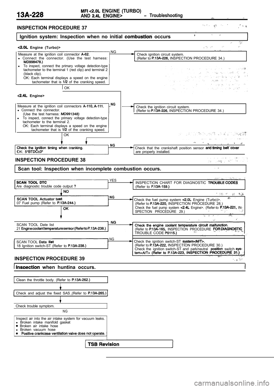
INSPECTION PROCEDURE 37 ,
Ignition system: Inspection when no initial occurs,
Engine (Turbo)> NGMeasure at the ignition coil connector Check ignition circuit system.
l Connect the connector. (Use the test harness:
(Refer to INSPECTION PROCEDURE 34.)
lTo inspect, connect the primary voltage detection-typetachometer to the terminal 1 (red clip) and terminal 2
(black clip).
OK: Each terminal displays a speed on the engine tachometer that is
of the cranking speed.
OK
Engine>
Measure at the ignition coil connectors
l Connect the connector.
(Use the test harness:
lTo inspect, connect the primary voltage detection-t ypetachometer to the terminal 2.OK: Each terminal displays a speed on the engine
tachometer that is of the cranking speed.
OK
NGCheck the ignition circuit system.(Refer to INSPECTION PROCEDURE 34.)
OK:
NG Check that the crankshaft position sensor are properly installed.
INSPECTION PROCEDURE 38
Scan tool: Inspection when incomplete combustion oc curs.
YESINSPECTION CHART FOR DIAGNOSTIC Arediagnostic trouble code output (Refer to
SCAN TOOL Actuator te
07 Fuel pump (Refer toNG, Check the fuel pump system Engine (Turbo)>.(Refer to INSPECTION PROCEDURE 28.)Check the fuel pump system Engine>. (Refer-to IN-
SPECTION PROCEDURE 29.)
./I,’
SCAN TOOL Date list21(Refer to INSPECTION PROCEDURE TROUBLE CODE
NGSCAN TOOL Data Check the ignition switch-ST 18 Ignition switch-ST (Refer to (Refer to INSPECTION PROCEDURE 30.)
Check the ignition switch-ST andpark/neutralswitch
INSPECTION PROCEDURE 39 ,
when huntina occurs.
Clean the throttle body. (Refer to
I
Check and adiust the fixed SAS (Refer to
Check trouble symptom.
NG
Inspect air into the air intake system for vacuum l eaks.
l Broken intake manifold gasket
Broken air intake hose
l Broken vacuum hose
Page 609 of 2103
ENGINE (TURBO)
AND. ENGINE> Troubleshooting . ,
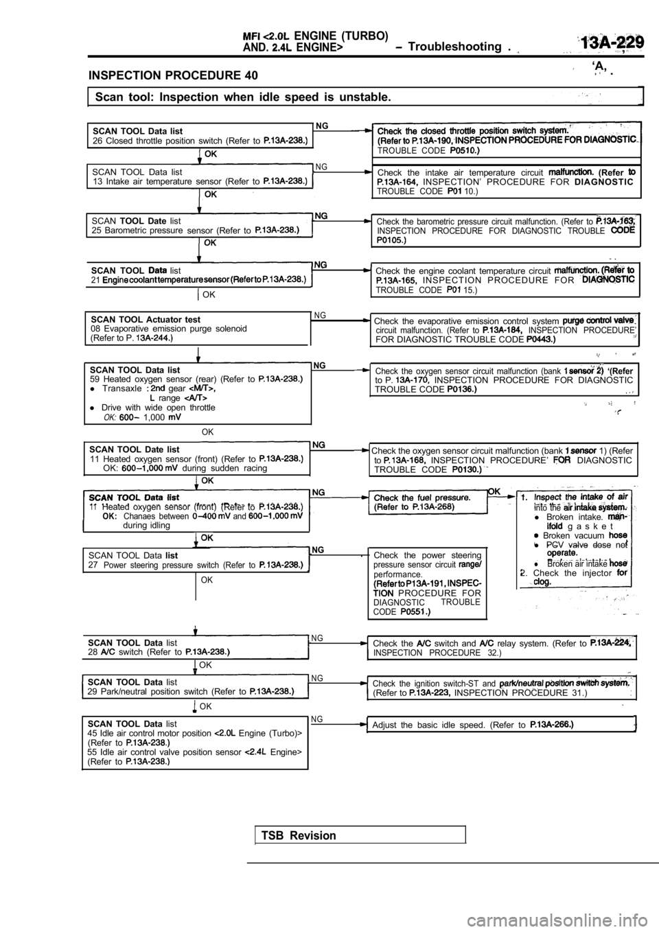
INSPECTION PROCEDURE 40
‘A, .
Scan tool: Inspection when idle speed is unstable.
SCAN TOOL Data list
NG
26 Closed throttle position switch (Refer to TROUBLE CODE
SCAN TOOL Data listNG Check the intake air temperature circuit (Refer 13 Intake air temperature sensor (Refer to INSPECTION’ PROCEDURE FOR DIAGNOSTICTROUBLE CODE 10.)
SCANTOOL Date listCheck the barometric pressure circuit malfunction. (Refer to 25 Barometric pressure
sensor (Refer toINSPECTION PROCEDURE FOR DIAGNOSTIC TROUBLE
.
SCAN TOOL list Check the engine coolant temperature circuit 21 I N S P E C T I O N P R O C E D U R E F O R
OKTROUBLE CODE 15.)
SCAN TOOL Actuator test
08 Evaporative emission purge solenoid
(Refer to P. NG Check the evaporative emission control system circuit malfunction. (Refer to INSPECTION PROCEDURE’FOR DIAGNOSTIC TROUBLE CODE
SCAN TOOL Data listNG
59 Heated oxygen sensor (rear) (Refer to l Transaxle gear range l Drive with wide open throttleOK: 1,000
OK
SCAN TOOL Date list11 Heated oxygen sensor (front) (Refer to OK: during sudden racing
Check the oxygen sensor circuit malfunction (bank ‘(Referto P. INSPECTION PROCEDURE FOR DIAGNOSTIC
TROUBLE CODE
Check the oxygen sensor circuit malfunction (bank 1) (Refer
to INSPECTION PROCEDURE’ DIAGNOSTIC
TROUBLE CODE
11Heated oxygen sensor (front) (Refer toOK:Chanaes between and during idlingI
SCAN TOOL Data listNG.
27
Power steering pressure switch (Refer to
OK
Check the power steeringpressure sensor circuit performance.
PROCEDURE FORDIAGNOSTIC TROUBLE
CODE
into the l Broken intake. g a s k e t Broken vacuum l PCV valve dose not
lBroken air intake 2. Check the injector
SCAN TOOL Data list
28 switch (Refer to
OK
N GCheck the switch and relay system. (Refer to INSPECTION PROCEDURE 32.)
SCAN TOOL Data listN G
29 Park/neutral position switch (Refer to Check the ignition switch-ST and (Refer to INSPECTION PROCEDURE 31.)
OK
SCAN TOOL Data list
45 Idle air control motor position Engine (Turbo)>
(Refer to
55 Idle air control valve position sensor Engine>
(Refer to
NGAdjust the basic idle speed. (Refer to
TSB Revision
Page 618 of 2103
ENGINE (TURBO)
AND
ENGINE>
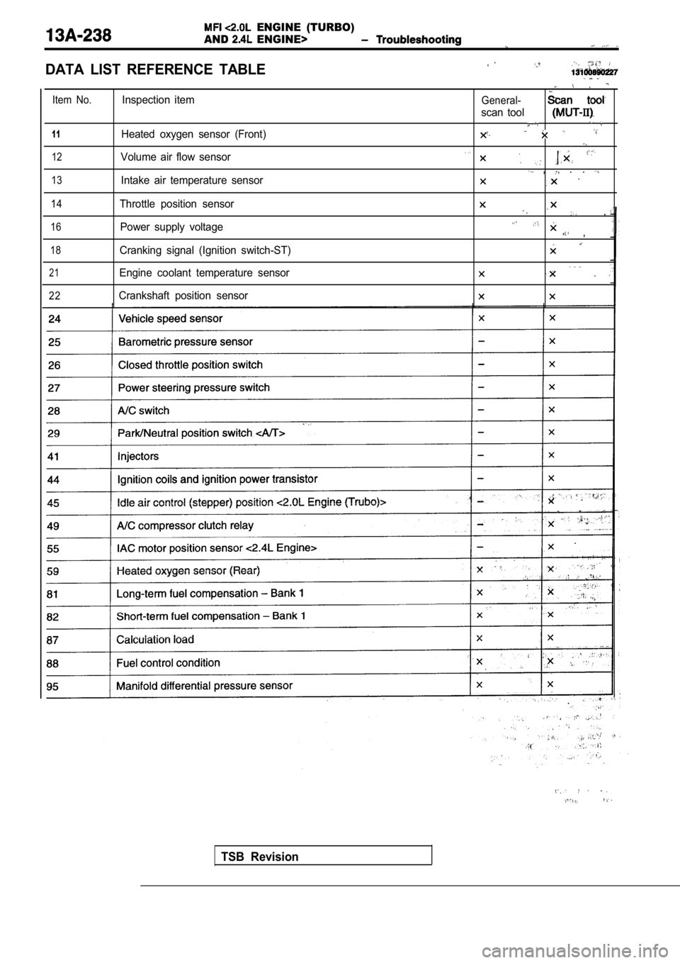
DATA LIST REFERENCE TABLE
Item No.
1 1
12
13
14
16
18
21
22
Inspection item
Heated oxygen sensor (Front)
Volume air flow sensor
Intake air temperature sensor
Throttle position sensor Power supply voltage
Cranking signal (Ignition switch-ST)
Engine coolant temperature sensor
Crankshaft position sensorGeneral-
scan tool
, . .
,
,
TSB Revision
Page 619 of 2103
ENGINE (TURBO)
AND ENGINE>
Caution
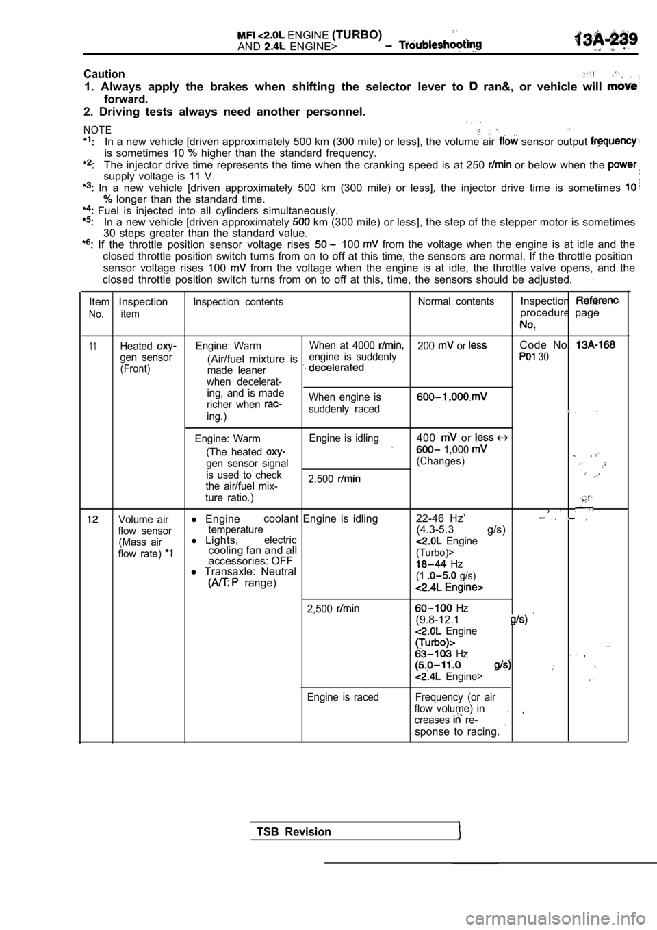
1. Always apply the brakes when shifting the select or lever to ran&, or vehicle will
forward.
2. Driving tests always need another personnel.
NOTE
In a new vehicle [driven approximately 500 km (300 mile) or less], the volume air sensor output
is sometimes 10 higher than the standard frequency.
The injector drive time represents the time when the cranking speed is at 250 or below when the
supply voltage is 11 V.
In a new vehicle [driven approximately 500 km (300 mile) or less], the injector drive time is sometimes
longer than the standard time.
Fuel is injected into all cylinders simultaneously.
In a new vehicle [driven approximately km (300 mile) or less], the step of the stepper mo tor is sometimes
30 steps greater than the standard value.
If the throttle position sensor voltage rises 100 from the voltage when the engine is at idle and th e
closed throttle position switch turns from on to of f at this time, the sensors are normal. If the throttle position
sensor voltage rises 100
from the voltage when the engine is at idle, the t hrottle valve opens, and the
closed throttle position switch turns from on to of f at this, time, the sensors should be adjusted.
Item Inspection
No.item
Inspection contents Normal contentsInspection
procedure page
11HeatedEngine: WarmWhen at 4000 200 or Code No.
gen sensor engine is suddenly(Air/fuel mixture is 30
(Front)
made leaner
when decelerat- ing, and is made
richer when
When engine is
suddenly raceding.)
Engine: Warm Engine is idling
400 or
(The heated 1,000 ,gen sensor signal(Changes)
is used to check
2,500
the air/fuel mix-
ture ratio.)
Volume airl Engine coolant Engine is idling 22-46 Hz’
flow sensortemperature(4.3-5.3 g/s)
(Mass airl
Lights,electric
flow rate) cooling fan and all Engine
accessories: OFF(Turbo)>
l Transaxle: Neutral Hz
range)(1 g/s)
2,500
Engine is raced
Hz
(9.8-12.1
Engine,
Hz ,
Engine>
Frequency (or air
flow volume) in
creases
re- ,
sponse to racing.
TSB Revision
Page 620 of 2103
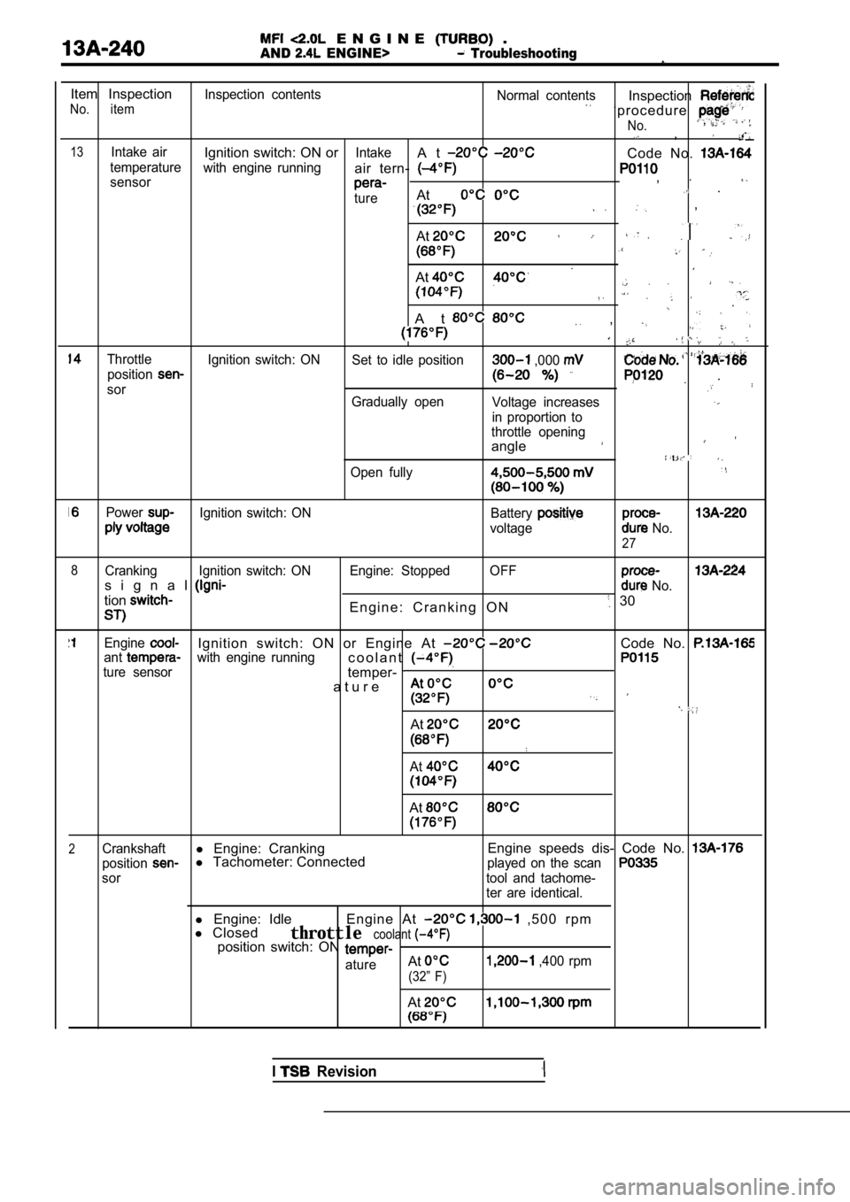
E N G I N E .
AND ENGINE> Troubleshooting
Item InspectionInspection contentsNormal contents
No. itemInspection
‘ p r o c e d u r e
No., ,
13Intake airIgnition switch: ON orIntakeA tCode No. temperaturewith engine runningair tern- sensor,
tureAt .
,
At
At
A t ,
Throttle Ignition switch: ON Set to idle position ,000 position
sor .
Gradually openVoltage increases
in proportion to
throttle opening
angle
Open fully
PowerIgnition switch: ON Battery
voltage No.
27
8
Cranking Ignition switch: ON Engine: Stopped OFF
s i g n a l No.
tionE n g i n e : C r a n k i n g O N 30
EngineIgnition switch: ON or Engine At Code No. antwith engine runningc o o l a n t
ture sensortemper-
a t u r e
At
At
At
2Crankshaftl Engine: Cranking Engine speeds dis- Code No.
positionl
Tachometer: Connectedplayed on the scan
sor tool and tachome-
ter are identical.
l Engine: Idle
l Closed Engine At , 5 0 0 r p m
throttlecoolantposition switch: ON
atureAt ,400 rpm
(32” F)
At
I Revision
Page 621 of 2103
ENGINE (TURBO)
AND
ENGINE>
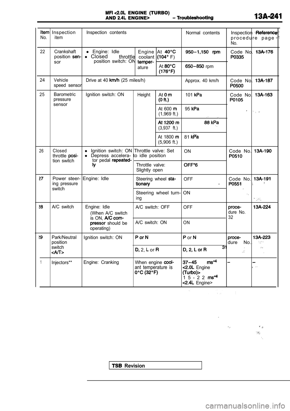
Inspection
No. item
Inspection contents Normal contentsInspection
p r o c e d u r e p a g e
No.
22
Crankshaftl Engine: Idle
Engine At Code No. position l Closed
throttlecoolant F)
sor position switch: ON
atureAt rpm
24VehicleDrive at 40 (25 miles/h)
Approx. 40 km/hCode No. speed sensor
25BarometricIgnition switch: ON
HeightAt101Code No. pressure
sensor
At 600 95
(1,969 ft.)
(3,937 ft.)
At 1800 81
(5,906 ft.)
26Closedl Ignition switch: ON Throttle valve: SetONCode No. throttlel Depress accelera- to idle position
tion switch tor pedal Throttle valve:
Slightly open
Power steer- Engine: IdleSteering wheel OFFCode No. ing pressure
switchSteering wheel turn- ON
ing
A/C switch
Engine: Idle
A/C switch: OFFOFF
(When A/C switchdure No.
is ON, 32
should beA/C switch: ONON
operating)
Park/Neutral
Ignition switch: ON or positiondure No..
switch 2, or
1Injectors**Engine: Cranking
When engine
ant temperature is Engine,
1 5 - 2 2
Engine>
Revision
Page 623 of 2103
E N G I N E ( T U R B O ) .AND ENGINE>
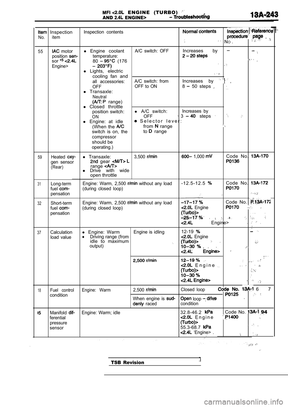
Inspection
No.item
Inspection contents , . N
O.
55 motorl Engine coolantA/C switch: OFFIncreases by
positiontemperature:
sor80 (176
Engine>
l Lights, electric
cooling fan and
all accessories: A/C switch: fromIncreases by ,
OFF OFF to ON8 50 steps
l
Transaxle:
Neutral
range)
l Closed throttle
position switch: l
A/C switch:
Increases by
ONOFF 3 steps
l Engine: at idle S e l e c t o r l e v e r :
(When the
from range
switch is on, the to range
compressor
should be
operating.)
59Heatedl
Transaxle:3,500 1,000 Code No.
gen sensor gear
(Rear)rangel Drive with wide
open throttle
31Long-term
fuel
pensation Engine: Warm, 2,500
without any load- 1 2 . 5 - 1 2 . 5Code No.
(during closed loop)
32Short-term
Engine: Warm, 2,500 without any loadCode No.
fuel(during closed loop) Engine
pensation
Engine> .
37Calculationl
Engine: WarmEngine is idling12-19
load valuelDriving range (from Engineidle to maximumoutput) .
,
E n g i n e
.
1 8Fuel control Engine: Warm2,500Closed loop 6 7
condition loop When engine is .
raced condition
ManifoldEngine: Warm; idle32.8-46.2Code No. 94
ferential E n g i n e
pressure
sensor55.3-68.7
‘Engine> .
TSB Revision