Page 1157 of 2103

AUTOMATIC TRANSAXLE .
ENGINE (NON-TURBO)> Troubleshooting.
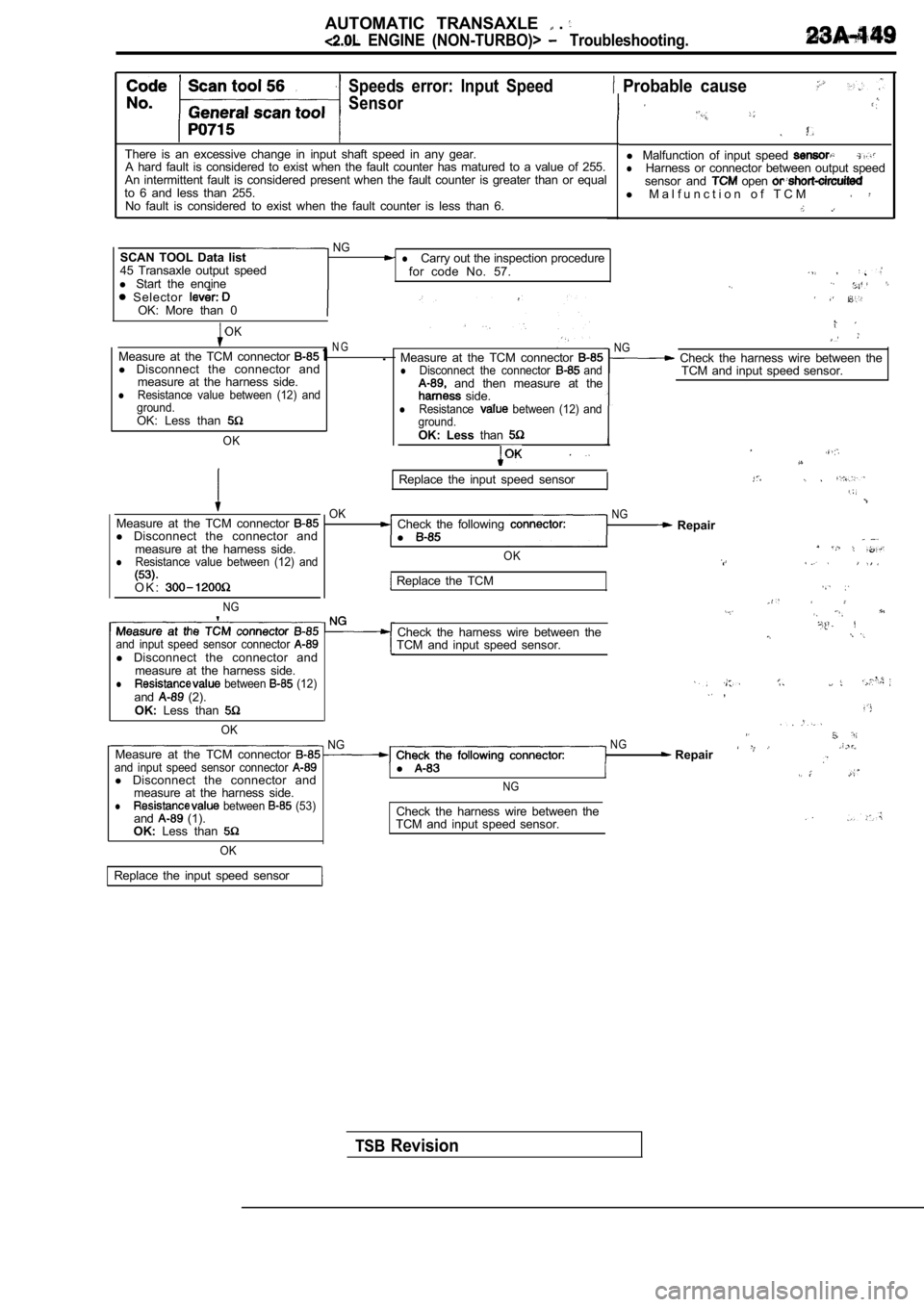
Speeds error: Input Speed
Sensor
There is an excessive change in input shaft speed in any gear.
A hard fault is considered to exist when the fault counter has matured to a value of 255.
An intermittent fault is considered present when th e fault counter is greater than or equal
to 6 and less than 255. No fault is considered to exist when the fault coun ter is less than 6.
Probable cause
l Malfunction of input speed lHarness or connector between output speed
sensor and open l M a l f u n c t i o n o f T C M
NGSCAN TOOL Data list lCarry out the inspection procedure
45 Transaxle output speed for code No. 57.
l Start the engine Selector OK: More than 0
OK
Measure at the TCM connector 1N G.
l Disconnect the connector and
measure at the harness side.
lResistance value between (12) and
ground.
OK: Less than
OK
Replace the input speed sensor
Measure at the TCM connector l Disconnect the connector and
measure at the harness side.
lResistance value between (12) and
OKCheck the following
l NG Repair
OK
O K :
NG
Replace the TCM
Check the harness wire between theand input speed sensor connector TCM and input speed sensor.
l Disconnect the connector and
measure at the harness side.
l between (12)and (2). ,
OK: Less than
OK NGNGMeasure at the TCM connector Repairand input speed sensor connector l l Disconnect the connector andmeasure at the harness side.NG
l between (53)and (1). Check the harness wire between theOK:
Less than TCM and input speed sensor.
OK
Measure at the TCM connector lDisconnect the connector and and then measure at the side.lResistance between (12) and
ground.
OK: Less than
NG Check the harness wire between the
TCM and input speed sensor.
Replace the input speed sensor
TSBRevision
Page 1158 of 2103

AUTOMATIC TRANSAXLE
ENGINE (NON-TURBO)>
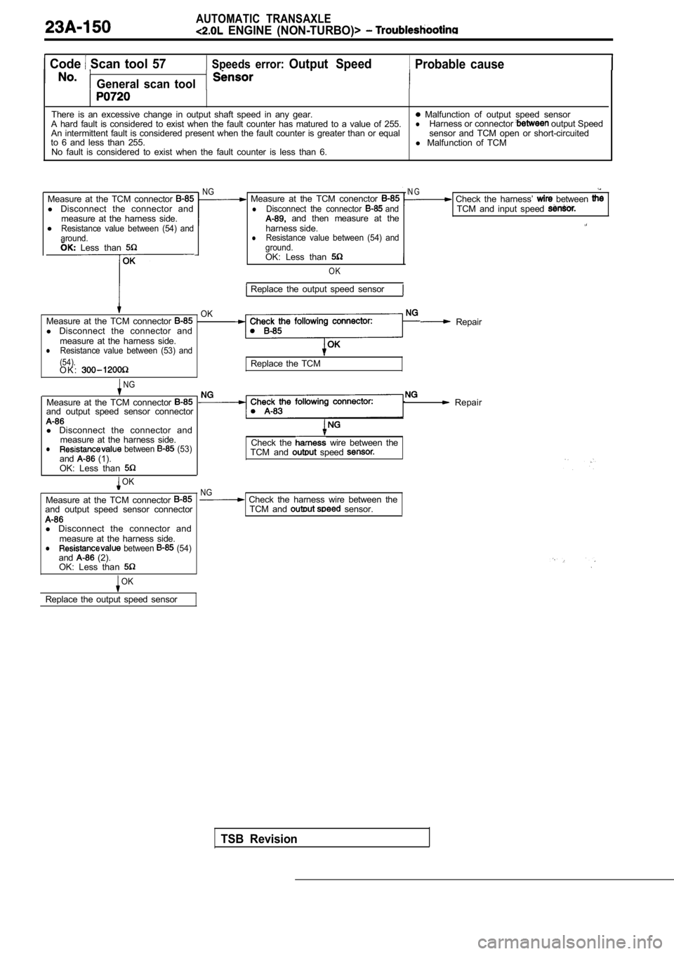
Code Scan tool 57 Speeds error: Output Speed Probable cause
General scan tool
There is an excessive change in output shaft speed in any gear. Malfunction of output speed sensor
A hard fault is considered to exist when the fault counter has matured to a value of 255.lHarness or connector output Speed
An intermittent fault is considered present when th e fault counter is greater than or equal sensor and TCM open or short-circuited
to 6 and less than 255. l Malfunction of TCM
No fault is considered to exist when the fault coun ter is less than 6.
Measure at the TCM connector
l Disconnect the connector and
measure at the harness side.
l
Resistance value between (54) and
around.
Measure at the TCM conenctor lDisconnect the connector and and then measure at the
harness side.
lResistance value between (54) and
ground. Less than
Measure at the TCM connector l Disconnect the connector and
measure at the harness side.
lResistance value between (53) and
(54).
OK
O K :
NG
OK: Less than
OK
Replace the output speed sensor
NG
Measure at the TCM connector and output speed sensor connector
l Disconnect the connector and
measure at the harness side.
l between (53)and (1).
OK: Less than
OK
Measure at the TCM connector and output speed sensor connector
l Disconnect the connector and
measure at the harness side.
l between (54)and (2).
OK: Less than
OK
Replace the output speed sensor
N G Check the harness’ between TCM and input speed
Check the following connector:Repair
Replace the TCM
Repair
Check the wire between the
TCM and speed
TSB Revision
NG Check the harness wire between the TCM and sensor.
Page 1160 of 2103
AUTOMATIC TRANSAXLE
ENGINE (NON-TURBO)> Troubleshooting
Code Scan tool 74Calculated oil temperature in use Probable cause
No.General scan tool
This code will set when the Transaxle Thermistor Voltage is below volts or abovel Malfunction of oil temperature sensor
4.9412 volts for 15 seconds, for 3 consecutive engi ne starts.l or connector between transaxle rangesensor and TCM open or short-circuited
l Malfunction of TCM
Oil temperature sensor check. (Refer to
NG Replace
N G
Measure at the transaxle range sensor Check
connector A-l 08 .
l Disconnect the connector and
measure at the harness side.OK
NG Repair
1. Voltage between (4) and ground.
l . 2 value between (3) and
transaxle range sensor and the TCM
Replace the TCM
Check the following connector: .NG Repair
OK
Check trouble symptom.
NGCheck the harness wire between the Repair
transaxle range sensor and the TCM
TSB Revision
Page 1162 of 2103
AUTOMATIC TRANSAXLE
ENGINE Troubleshooting
PROBABLE CAUSE
No.Probable cause
1Low fluid level
2Aerated fluid (High fluid level)
3Worn or damaged reaction shaft support sealing
4worn or damaged input shaft sealing
5Worn pump
6
Damaged or failed underdrive clutch
7Damaged or failed ovedrive clutch
8Damaged or failed reverse clutch
9Damaged or failed 2-4 clutch
10Damaged or failed low/reverse clutch
11Damaged clutch seal
12Worn or damaged accumulator sealing
13Plugged filter
14Stuck/sticky valves
15Solenoid switch valve
16Lock-up switch valve
17Torque converter control valve
18Regulator valve
19Valve body leakage
20Pressures too high
21Internal solenoid leak
22Torque converter clutch failure
23Faulty cooling system
24Damaged speed sensor gear teeth
25Planetary gear sets broken or seized
.
,
TSB Revision
Page 1165 of 2103

AUTOMATIC TRANSAXLE
ENGINE (NON-TURBO)>
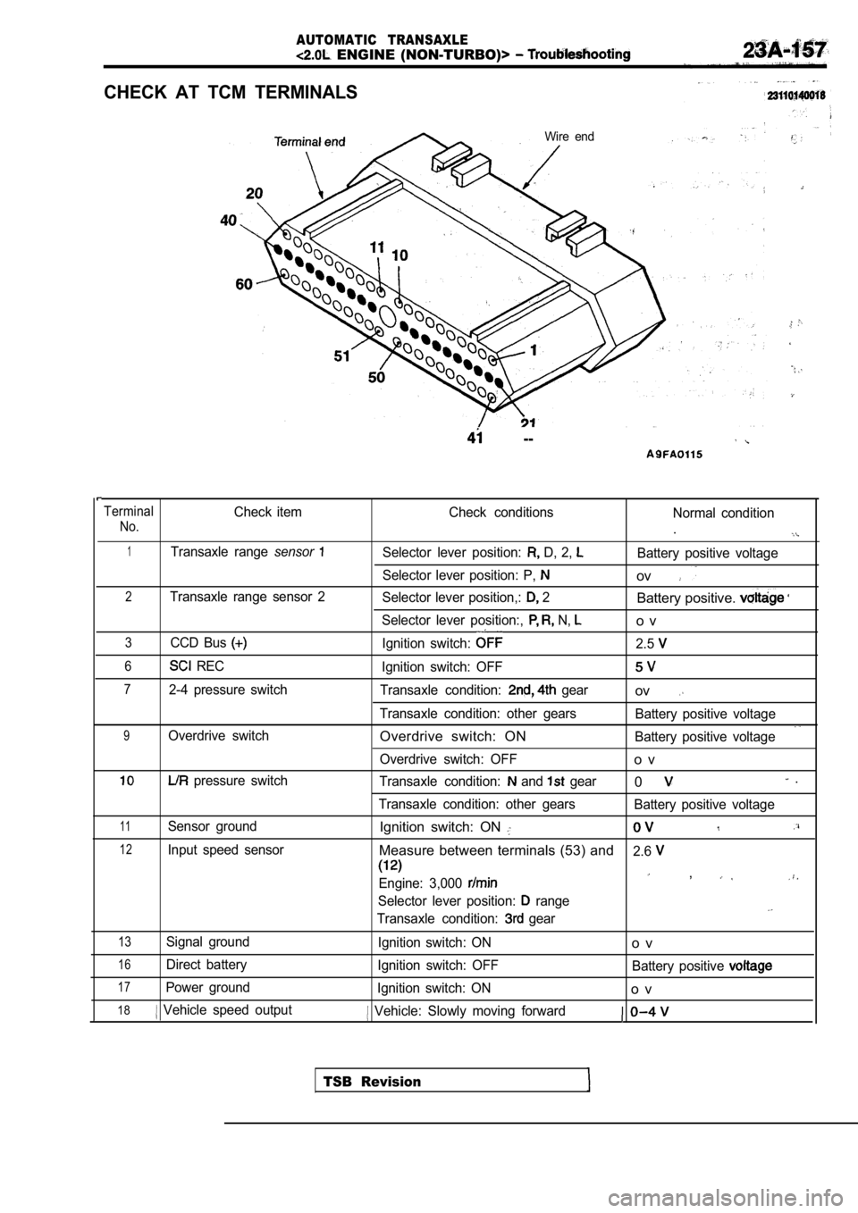
CHECK AT TCM TERMINALS
Wire end
--
TerminalCheck itemCheck conditions
Normal condition
No..
1Transaxle range sensorSelector lever position: D, 2, Battery positive voltage
Selector lever position: P,
ov
2Transaxle range sensor 2 Selector lever position,: 2Battery positive.
Selector lever position:, N, o v
3CCD Bus Ignition switch: 2.5
6 RECIgnition switch: OFF
72-4 pressure switch Transaxle condition: gearov
Transaxle condition: other gears Battery positive voltage
9Overdrive switchOverdrive switch: ONBattery positive voltage
Overdrive switch: OFF
o v
pressure switch Transaxle condition: and gear0 .
Transaxle condition: other gears Battery positive voltage
11Sensor groundIgnition switch: ON
12Input speed sensorMeasure between terminals (53) and2.6
Engine: 3,000 ,
Selector lever position: range
Transaxle condition: gear
13Signal ground
Ignition switch: ONo v
16Direct batteryIgnition switch: OFF Battery positive
17Power groundIgnition switch: ONo v
18 Vehicle speed output Vehicle: Slowly moving forward
TSB Revision
Page 1166 of 2103

AUTOMATIC TRANSAXLE
ENGINE Troubleshootina
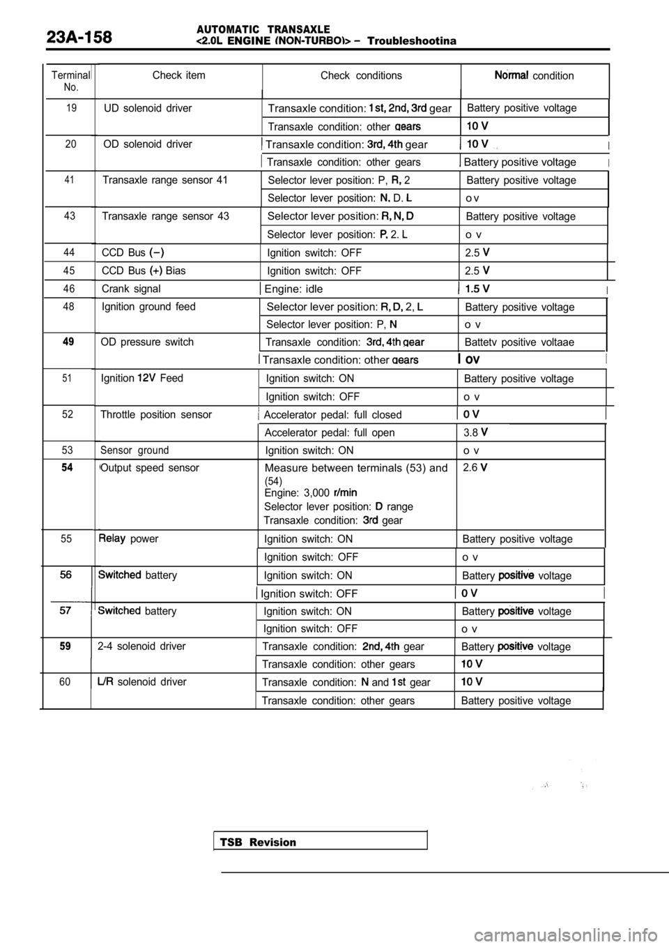
Terminal
No.19
Check item Check conditions condition
UD solenoid driver
Transaxle condition: gearBattery positive voltage
Transaxle condition: other
20OD solenoid driver Transaxle condition: gearI
Transaxle condition: other gears Battery positive voltageI
41Transaxle range sensor 41 Selector lever position: P, 2 Battery positive voltage
Selector lever position:
D. o v
43Transaxle range sensor 43Selector lever position: Battery positive voltage
Selector lever position:
2. o v
44
45
46
48CCD Bus Ignition switch: OFF 2.5
CCD Bus Bias Ignition switch: OFF 2.5
Crank signal Engine: idleI
Ignition ground feed
OD pressure switchSelector lever position: 2, Battery positive voltage
Selector lever position: P,
o v
Transaxle condition: Battetv positive voltaae49
Transaxle condition: other I ovI
51Ignition Feed Ignition switch: ON Battery positive voltage
Ignition switch: OFF
o v
52Throttle position sensor Accelerator pedal: full closedI
53
54
55 Sensor ground
Output speed sensor
power Accelerator pedal: full open 3.8
Ignition switch: ONo v
Measure between terminals (53) and
2.6
(54)
Engine: 3,000
Selector lever position: range
Transaxle condition:
gear
Ignition switch: ON Battery positive voltage
TSB Revision
battery Ignition switch: OFF
o v
Ignition switch: ON
Battery voltage
Ignition switch: OFFI
batteryIgnition switch: ON Battery voltage
Ignition switch: OFF
o v
592-4 solenoid driver Transaxle condition: gearBattery voltage
60 solenoid driver Transaxle condition: other gearsTransaxle condition: and gear
Transaxle condition: other gearsBattery positive voltage
Page 1168 of 2103
AUTOMATIC TRANSAXLE
ENGINE (NON-TURBO)> On-vehicle Service
TRANSAXLE RANGE SENSOR CONTINUITY
CHECK
(1) Disconnect the transaxle range sensor connector.
(2) Check the continuity between sensor terminals a nd body
ground (and terminals while shifting the
lever at each position. The continuity between sensor
terminals and body ground (and terminals
should
be as shown in the table below.
LeverTerminal No. Body
,
TSB Revision
(3) If there is a defect, replace the transaxle ran ge sensor.
OIL TEMPERATURE SENSOR CONTINUITY
CHECK
(1) Disconnect thetransaxle range sensor connector.
(2) Measure the resistance between terminals 2-3 an d check
that the values are as shown in the table below.
Oil temperature Resistance value
(32)29.33 35.99
100 (212)640720
(3) If the values are outside the standard values, replace
the transaxle range sensor.
Page 1169 of 2103
AUTOMATIC TRANSAXLE
ENGINE (NON-TURBO)>
AUTOMATIC TRANSAXLE CONTROL COMPONENT LAYOUT
Output speed sensorTransaxle
TSB Revision