Page 1713 of 2103

Service
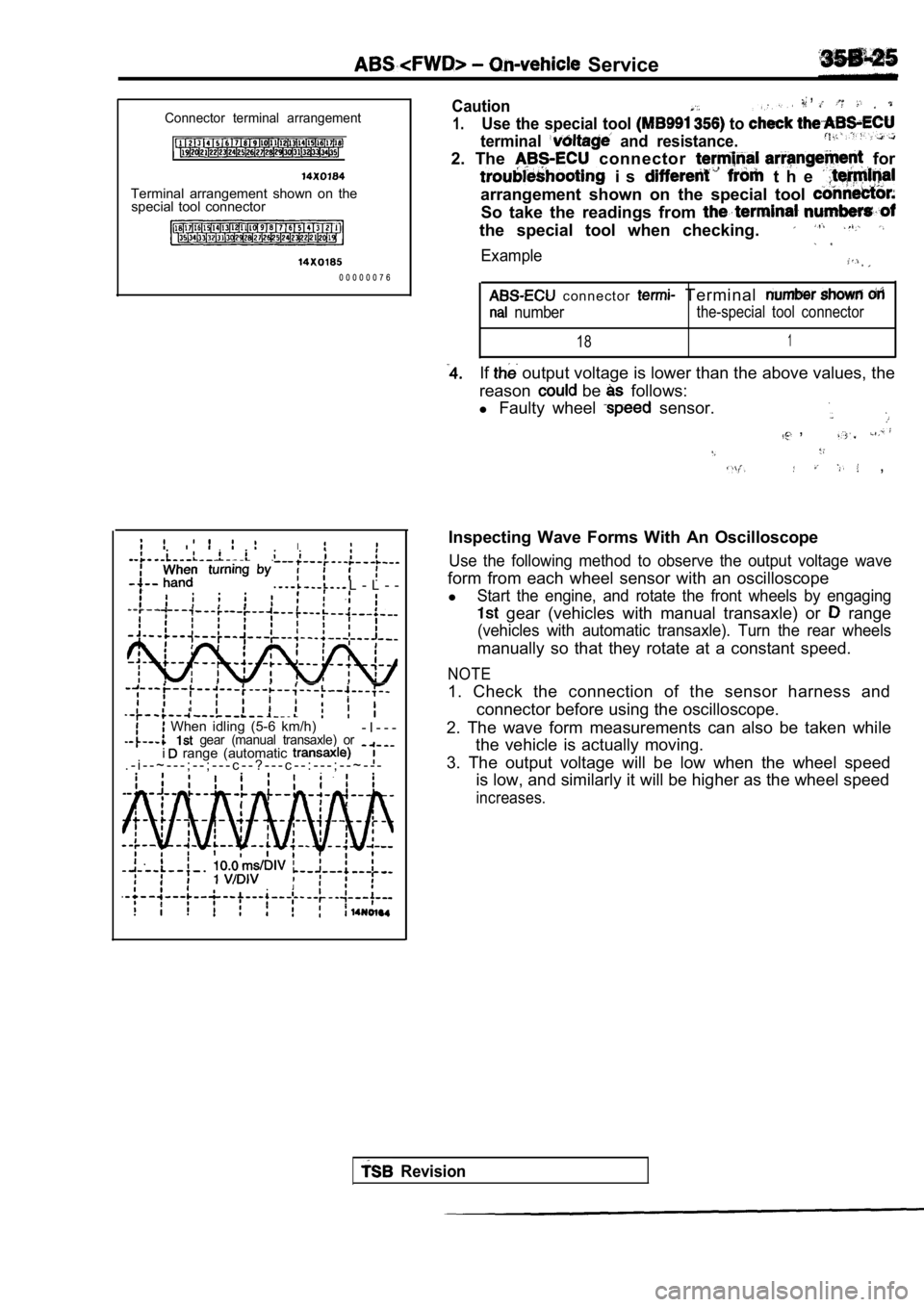
Connector terminal arrangement
Terminal arrangement shown on thespecial tool connector
0 0 0 0 0 0 7 6
L - L - -
,
I
When idling (5-6 km/h) gear (manual transaxle) or- I - - -
. - i - - ~ - - - ; - - ; - - - c - - ? - - - c - - : - - - ; - - ~ - - - i range (automatic
,Caution,
1.Use the special tool to
terminal and resistance.
2. The connector for
i s t h e
arrangement shown on the special tool
So take the readings from
the special tool when checking.
Example
c o n n e c t o r Terminal
numberthe-special tool connector
181
If output voltage is lower than the above values, the
reason
be follows:
l Faulty wheel
sensor.
,
,
Inspecting Wave Forms With An Oscilloscope
Use the following method to observe the output volt age wave
form from each wheel sensor with an oscilloscope
l
Start the engine, and rotate the front wheels by en gaging
gear (vehicles with manual transaxle) or range
(vehicles with automatic transaxle). Turn the rear wheels
manually so that they rotate at a constant speed.
NOTE
1. Check the connection of the sensor harness and
connector before using the oscilloscope.
2. The wave form measurements can also be taken whi le
the vehicle is actually moving.
3. The output voltage will be low when the wheel sp eed
is low, and similarly it will be higher as the whee l speed
increases.
Revision
Page 1714 of 2103
On-vehicle Service .
Points In Waveform Measurement
SymptomProbable causes
Too small or zero waveform
Faulty wheel speed sensor Replace sensor
amplitude
. .
Waveform amplitude fluctuates Axle hub eccentric or with large
cessively (this is no problem if the
Replace
minimum amplitude is 100 or
more)
Noisy or disturbed waveform Open circuit in sensorR e p l a c e s e n s o r
Open circuit in harness Correct harness
Incorrectly mounted wheel speed sensor Mount correctly
rotor with missing or damaged teethReplace ABS rotor
NOTE
The wheel speed sensor cable moves following motion
of the front or rear suspension. Therefore, it is that
it has an open circuit only when driving on rough r oads and it functions normally on ordinary roads.
is, therefore,
recommended to observe sensor output voltage wavefo rm also under conditions, such as rough road driving.
Revision
Page 1720 of 2103
ABS Master Cylinder and Brake Booster
MASTER CYLINDER AND BRAKE BOOSTER
REMOVAL AND INSTALLATION
(Refer to GROUP Master Cylinder and Brake Booster.)
MASTER CYLINDER
DISASSEMBLY AND REASSEMBLY
. .
,
13
TSBRevision
19 14
15
Master cylinder kit
Brake fluid:
steps
Reservoir bracket2.Reservoir hose3. Reservoir cap assembly4.Diaphragm5.Reservoir cap6.Filter7. Brake fluid level sensor8,Float9.Reservoir10.Pin
Retainer12.Connector13.Grommet14. Piston stopper bolt15.Gasket
16. Piston stopper ring
17. Primary piston assembly
18. piston assembly19. Master cylinder body
CautionDo not disassemble the primary and secondary piston
assembly.
Page 1726 of 2103
ABS W h e e l S p e e d S e n s o r
WHEEL SPEED SENSOR
REMOVAL AND INSTALLATION
Operationl Splash Shield Removal
Installation Splash Shield
Front ,
Rear 49-59
74-66
4
Front wheel speed sensor removalsteps
1. Clip 2. Front wheel speed sensor Front ABS rotor removal3. Drive shaft
(Refer to GROUP 26 Drive
Shaft.)
Rear wheel speed sensor removal
4. Rear wheel speed sensor
Rear ABS rotor removal steps
5. Caliper assembly
6. Brake disc
7. Shoe and lining assembly
(Refer to GROUP 36 Parking
Brake Drum.)8. Rear hub assembly
9. Rear ABS rotor
NOTEThe front ABS rotor, integrated with the drive shaf t, can not be dis-assembled.
TSB Revision
Page 1727 of 2103

ABS Wheel
INSTALLATIONFrontRear
FrontRear
Magnetic parts
0 C C
WHEEL SPEED SENSOR/REAR WHEEL
S P E E D
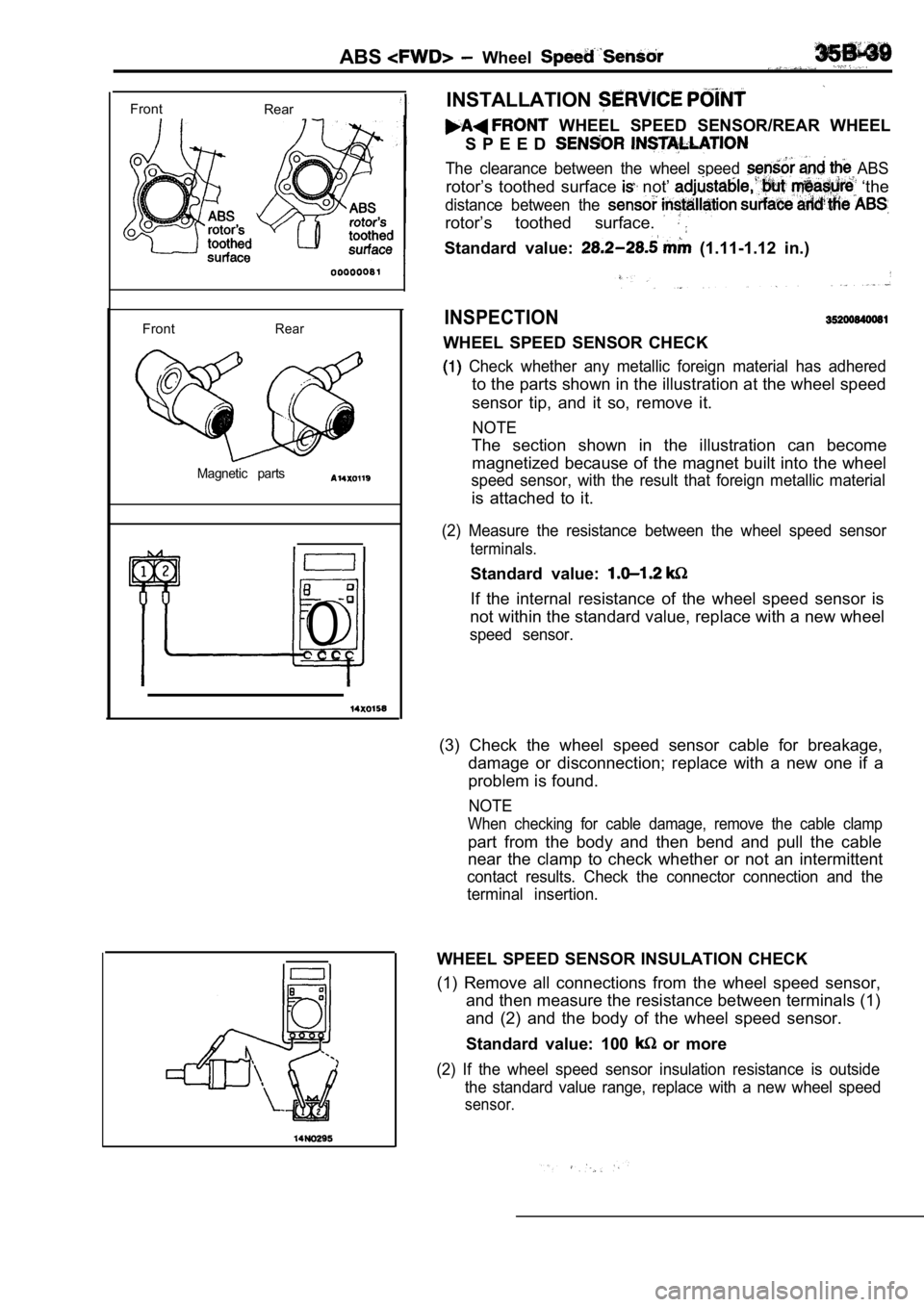
The clearance between the wheel speed ABS
rotor’s toothed surface not’ ‘the
distance between the
rotor’s toothed surface.
Standard value: (1.11-1.12 in.)
INSPECTION
WHEEL SPEED SENSOR CHECK
Check whether any metallic foreign material has ad hered
to the parts shown in the illustration at the wheel speed
sensor tip, and it so, remove it.
NOTE
The section shown in the illustration can become magnetized because of the magnet built into the whe el
speed sensor, with the result that foreign metallic material
is attached to it.
(2) Measure the resistance between the wheel speed sensor
terminals.
Standard value:
If the internal resistance of the wheel speed sensor is
not within the standard value, replace with a new w heel
speed sensor.
(3) Check the wheel speed sensor cable for breakage ,
damage or disconnection; replace with a new one if a
problem is found.
NOTE
When checking for cable damage, remove the cable cl amp
part from the body and then bend and pull the cable
near the clamp to check whether or not an intermittent
contact results. Check the connector connection and the
terminal insertion.
WHEEL SPEED SENSOR INSULATION CHECK
(1) Remove all connections from the wheel speed sen sor,
and then measure the resistance between terminals ( 1)
and (2) and the body of the wheel speed sensor.
Standard value: 100
or more
(2) If the wheel speed sensor insulation resistance is outside
the standard value range, replace with a new wheel speed
sensor.
Page 1731 of 2103

CONTENTS
ABS-ECU. . . . . . . . . . . . . . . . . . . . . . . . . . . . . . . . .31 SERVICE SPECIFICATIONS . . . . . . . . . . . . . . . . . 3
GENERAL INFORMATION2SPECIAL TOOLS. . . . . . . . . . . . . . . . . . . . . . . . . . .3. . . . . . . . . . . . . . . . . .
G-SENSOR2 9. . . . . . . . . . . . . . . . . . . . . . . . . . . . . . .4
ON-VEHICLE SERVICE . . . . . . . . . . . .
. . . . 21WHEEL SPEED . . . . . . . . . . . . . . . . . .
ABS Operation Check . . . . . . . . . . . . . . . . . . . . . . . 21
Refer to for the following items.
BRAKE PEDAL
FRONT DISC BRAKE
LUBRICANTS
REAR DISC BRAKE
REAR DRUM BRAKE SHOE
REAR DRUM BRAKE WHEEL CYLINDER
ON-VEHICLE SERVICE
Brake Booster Operating Test
Brake Drum Inside Diameter Check
with Rear Drum Brakes>
Brake Fluid Level Sensor Check
Brake Lining and Brake Drum
Contact Check
Brake Lining Thickness Check Brake Pedal Check and Adjustment
Check Valve Operation Check
Front Brake Disc Run-out Check
Brake
Front Check and
Front Check
Proportioning Valve Test
Rear Brake Check
Rear Brake Disc Run-out Correction
Rear Brake Disc Thickness Check
Rear Disc Brake Pad Check and Replacement
Stop Light Switch Check
Refer to GROUP for the following items.
H Y D R A U L I C U N I T
MASTER CYLINDER AND BRAKE BOOSTER
PROPORTIONING VALVE
ON-VEHICLE
,
Bleeding,
Page 1732 of 2103
ABS General Information
G E N E R A L I N F O R M A T I O N
The ABS consists of wheel speed sensors, stop light switch, hydraulic unit and the ABS-ECU. If be erased even if the ignition switch is turned to
OFF.
a problem occurs in the system, the malfunctioning
system can be identified by
meansof the diagnostic
In addition, reading of diagnostic trouble codes
function, and the trouble symptom memory will’ not and service data
actuator testing are possible
using
the scan tool.
S p e c i f i c a t i o n s
Wheel speed sensorMagnet coil type
Front ABS rotor
Rear ABS rotor teeth
D I A G R A M
1. ABS-ECU2. Hydraulic unit ABS valve relay
4. ABS motor relay
5. Wheel speed sensor
6. ABS rotor D a t a 9. switch
10. ABS light11. G-sensor
TSB Revision
Page 1733 of 2103
A B S Service Tools
SERVICE SPECIFICATIONS
Standard value
. . .Hydraulic unit solenoid valve internal resistance
Clearance between the wheel speed sensor (1.11-1.12)
mounting surface and the ABS rotor mm (in.)
G-sensor output voltage In laden, stationary 2.4-2.8
With FRONT mark downward3.3-3.7
Wheel speed sensor insulation resistance or more
SPECIAL TOOLS
Scan tool (MUT-II)
l system inspection
ABS check harness
Test harness set
Diagnostic trouble code
check harness
Revision