Page 2045 of 2103

HEATER, AIR Service
AND VENTILATION Special Tools
SERVICE SPECIFICATIONS
IStandard value ‘I
speed E n g i n e ( T u r b o ) a n d
EngineII
Engine (Non-turbo)I
up speed
Resistor (for blower motor) LO
100 in Neutral
1.83
MHI 0.31
Revolution pick up sensor standard resistance
Engine (Non-turbo)>
185
[when ambient temperature is
Refrigerant temperature switch ON (continuity) tempe rature
Engine (Turbo) and
Engine>OFF (no continuity) temperature
Approx. or less
Approx. or more
(until the temperature drops to approx.
when OFF)
Air gap (Magnetic clutch) mm (in.)
Engine (Turbo) and
Engine
Engine (Non-turbo)I
LUBRICANTS
ItemsSpecified lubricants Quantity
Each connection of refrigerant line ND-OIL 8 Engine (Non-turbo)>, SUN PAG 56 As required
Engine (Turbo) and Engine>
Lip seal of the compressor ND-OIL 8
Engine (Non-turbo)>As required
Compressor refrigerant unit lubricant SUN PAG 56
lubricant
Engine (Turbo) and Engine>
ND-OIL 8
Engine (Non-turbo)>
SPECIAL TOOLS
ToolTool number and nameSupersession Application
367Armature mounting nut of com-
e S p e c i a l s p a n n e r removal and installation
Engine (Turbo) and
Engine>
386
Pin
TSB Revision
Page 2046 of 2103

HEATER, AIR
AND VENTILATION Troubleshooting
TROUBLESHOOTING
PROCEDURES
Trouble
symptom
When the ignitior
switch is “ON”,
the
does not
operate.
conditioning
does not
when
he air outlet
knob is
noved to the
or
position. Problem cause
compressor clutch relay
is defective
Magnetic clutch is defective
Refrigerant leak or overfilling
of refrigerant
Dual pressure switch is defec-
tive
A/C switch is defective Blower switch is defective
Fin
sensor is defective
Refrigerant temperature switch
is defective
Engine (Tur-
bo) and
Engine>
Automatic compressor-ECM
is defective
Revolution pick up sensor is
defective
Engine (Non-turbo)>
A/C compressor relay is de-
fective
1
Dual pressure switch is defec-
tive
Defroster switch is defective
TSB Revision
Magnetic clutch is defective
Refrigerant leak or overfilling
of refrigerant Remedy
Reference ReferencepagepageEngine
Engine(Non-turbo) (Turbo) Engine
Replace A/C compressor clutch 55-1855-18
relay
Replace the armature plate, rotor55-34
or clutch coil
Replenish the refrigerant, repair
0
the leak or take out some of therefrigerant
Replace the dual pressure switch 55-45
Replace the A/C switch 55-2355-23
Replace the blower switch55-22 55-22
Replace the fin sensor
Replace the refrigerant tempera-
ture switch
Replace the automatic
Replace the revolution pick up
sensor
55-26
Replace A/C compressor clutch55-18
relay
Replace the armature plate, rotor55-34
or clutch coil
Replenish the refrigerant, repair
the leak or take out some of the
refrigerant
Replace the dual pressure switch55-45
the defroster switch55-22 55-22
the blower switch55-225 5 - 2 2
temperature Replace the refrigerant tempera-
is defective
ture switch
compressor-ECU isReplace the automatic 55-26
sor-ECU
pick up sensor is
Replace the revolution pick up
sensor Engine
Page 2047 of 2103

HEATER, AIR
AND VENTILATION Troubleshooting
Trouble
symptomProblem cause
Remedy
ReferencepageEngine Engine’
(Non-turbo)(Turbo) and Engine
When the A/C isRefrigerant leak
Replenish the refrigerant and 0o p e r a t i n g , t e r n -pair the leakperature inside
the passengerDual pressure switch is Replace the dual pressure switch55-45
compartmenttive
(no cool air).Fin sensor is defective
Replace the fin sensor
Refrigerant temperature switch Replace the refriger ant tempera-
is defective Engine (Tur-
ture switch
bo) and
Engine>
Automatic compressor-ECM Replace the automatic
55-26is defectivesor-ECM
Blower-motor/fan Blower moter relay is
Replace the blower moter relay55-1755-17inoperativetive
Blower fan and motor is Replace the blower fan and motor55-26
Resistor (for blower motor) is
Replace the resistor55-26
defective
Blower switch is defective Replace the blower switch
55-2255-22
Blower fan and Short circuit of the harness Repair the harness
motor keeps
between the blower fan and
ningmotor and the blower switch
Blower switch is defective Replace the blower switch
55-2255-22
Blower relay is defective
Replace the blower moter relay 55-1755-17
the A/C is Condenser fan motor is Replace the condenser fan motor55-47 55-46
fan Condenser fan relay (LO) is
Replace the condenser fan relay 55-18
defective
Condenser fan relay (HI) is Replace the condenser fa n relay55-1855-18
defective
INSPECTION AT THE AUTOMATIC COMPRESSOR-ECM TERMINAL
Engine (Turbo) and Engine>
Terminal No.Name of Signal Check requirementsTerminal voltage
1Automatic compressor-ECM power The ignition switch, blower switch Battery positive
supply (output side) and A/C switch are all ON
v o l t a g e
2Automatic compressor-ECM power
supply (input side)
The ignition switch,
and switch are all ON Batteryvoltage
3A u t o m a t i c c o m p r e s s o r - E C M g r o u n d o v
TSB Revision
Page 2048 of 2103

55-8HEATER, AIR
AND VENTILATION Troubleshooting/On-vehicle Service
Engine (Non-turbo)>
12
Sensor ground
Automatic compressor-ECM power
supply (output side)
Fin sensor power supply
o v
The ignition switch, blower switch andBattery positive
switch areall ONvoltage
The ignition switch, blower switch and
A/C switch are all ON
TROUBLESHOOTING HINTS
l R e f e r t o C O O L I N G S Y S T E M
SHOOTING.
Refer to
Terminal No.Name of Signal
Check requirements Terminal voltage
compressor clutch relay
When the compressor ON conditions Battery positive
are satisfied voltage
2Automatic compressor-ECM groundov
4Automatic compressor-ECM power
The ignition switch, blower switch and Battery positive
supply (input side) switch are all ONvoltage
5Automatic compressor-ECM powerTheignition switch is ONBattery positive
voltage
Engine (Turbo) and Engine>I
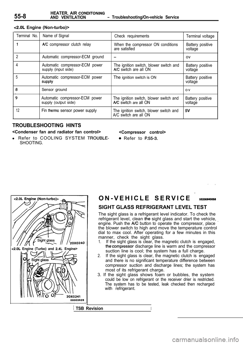
O N - V E H I C L E S E R V I C E
SIGHT GLASS REFRIGERANT LEVEL TEST
The sight glass is a refrigerant level indicator. T o check the
refrigerant level, clean
sight glass and start the vehicle,
engine. Push the button to operate the compressor, place
the blower switch to high and move the temperature control
dial to max cool. After operating for a few minutes in this
manner, check the sight glass.
1.If the sight glass is clear, the magnetic clutch is engaged,
discharge line is warm and the compressor
suction line is cool; the system has a full charge.
2.If the sight glass is clear, the magnetic clutch is engaged
and there is no significant temperature difference between
compressor suction and discharge lines; the system has
most of its refrigerant charge.
3. If the sight glass shows foam or bubbles, the sy stem
could be low on refrigerant or the receiver drier is restricted.
The system has to be tested, leak checked then rech arged
with refrigerant.
TSB RevisionI
Page 2065 of 2103
HEATER, AIR
AND VENTILATION Heater Unit
HEATER HOSE DISCONNECTION”
Caution
The vehicle speed sensor for ‘below
the heater, hoses, so cover vehicle
a shop towel before any of the
Pin
Grommet
Pin
CLIP REMOVAL
‘(1) Use a Philips-head screwdriver to push inward the pin
(at the center of the clip) to adepth of about
in.).
(2) the clip outward to remove. it.
Caution
Do not push the pin inward more than be-
cause it may damage the grommet, or the
may
fall in, if pushed too far.
HEATER UNIT
After the cooling unit slightly, remove
the heater unit.
INSTALLATION SERVICE POINT .
CLIP INSTALLATION
(1) With the pin pulled out, insert the clip into t he hole.
(2) Push the pin inward until the pin’s head is flu sh with
the grommet.
TSB Revision
Page 2070 of 2103
HEATER, AIR
AND VENTILATION Cooling Unit
DISASSEMBLY AND REASSEMBLY5 5 2 0 1 0 6 0 0 2 6
7
oil:
SUN PAG 56
Engine
(Turbo) and Engine>
ND-OIL 6
Engine
(Non-turbo)>
0 0 0 0 3 6 3 5
Disassembly steps
1. Clip
2. Evaporator case (upper)
3. Fin sensor Engine (Non-turbo)>
4. Automatic compressor-ECM and fin
sensor assembly En-
gine (Turbo) and Engine> 5. Evaporator case (lower)
6. Expansion valve
7. O-ring
8. Evaporator
Resis-
tance
1 02030 40(14) (50) (68) (86) Temperature
INSPECTION
FIN SENSOR RESISTANCE CHECK
When the resistance value between the sensor termin als
is measured under two or more temperature condition s, the
resistance value should be close to the values show n in the
graph.
NOTE
Thetemperature conditions when testing should not exceed
the range of the characteristic curve in the graph.
TSB Revision
DISASSEMBLY SERVICE POINT
CLIP REMOVAL
Remove the clips with a flat-tipped screwdriver cov ered with
a shop towel to prevent damage to case surfaces.
Page 2072 of 2103

HEATER, AIR
AND VENTILATIONCompressor’ and Pulley Engine (Turbo) and
INSTALLATION
COMPRESSOR INSTALLATION
If a new compressor is installed, first adjust the amount of
oil according to the procedures described below, an d then
install the compressor.
(1)Measure the amount (x of oil within the
removed compressor.
(2) Drain (from the new compressor) the amount of o il calcu-
lated according to the following formula, and then install
then new compressor.
New compressor oil amount
170
(1) (y indicates the amount of oil in the
refrigerant line, the condenser, the evaporator
. .
R E M O V A L S E R V I C E P O I N T S
FLUID
Disconnect the brake fluid level sensor connector a nd, remove
the brake fluid reservoir from the compressor
the hose still attached.
NOTE
Place the removed brake fluid reservoir in where
it will not be a hindrance when removing and instal ling the
A/C compressor, and tie it
cord.
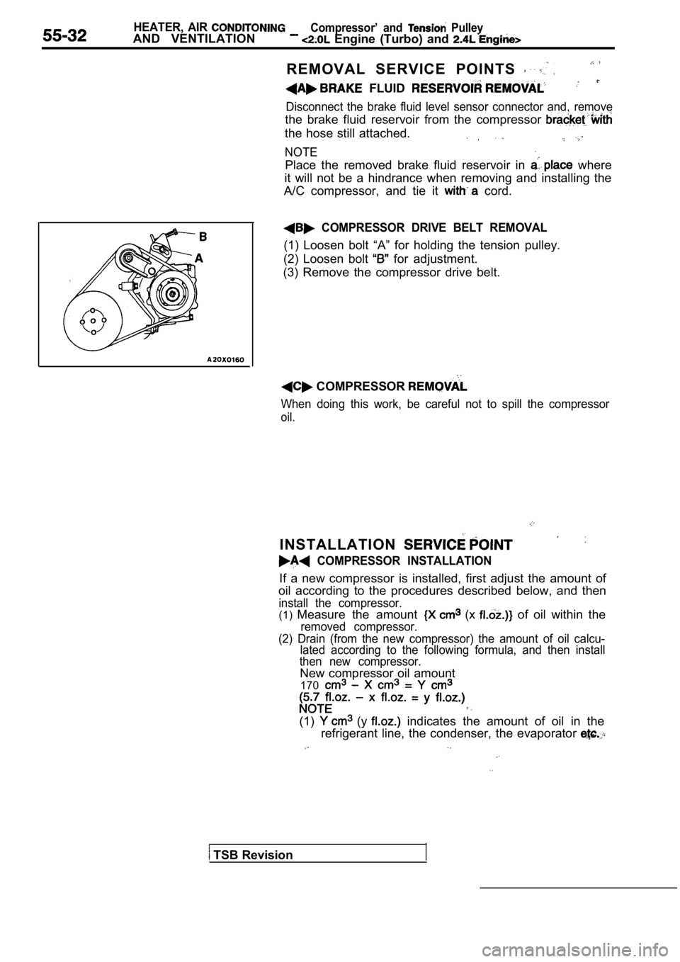
COMPRESSOR DRIVE BELT REMOVAL
(1) Loosen bolt “A” for holding the tension pulley.
(2) Loosen bolt
for adjustment.
(3) Remove the compressor drive belt.
COMPRESSOR
When doing this work, be careful not to spill the c ompressor
oil.
TSB Revision
Page 2080 of 2103
00003640
l Air gap adjustment1.Clutch hub2.Shim3.Snap ring4.Rotor assembly5.Snap ring 6. Clutch coil 7. Front housing
h o l d e r
Snap ring
High-pressure relief valve14. O-ring15. Revolution pickup sensor